FORD F650 2013 12.G Owners Manual
Manufacturer: FORD, Model Year: 2013, Model line: F650, Model: FORD F650 2013 12.GPages: 378, PDF Size: 3.82 MB
Page 181 of 378
Towing the Vehicle with the Rear Wheels Suspended
Note:To avoid damage to the cab roof or air deflector when towing the
vehicle backward (rear wheels suspended), the air deflector must be
removed.
Whenever possible, it is preferable to tow a disabled vehicle from the
rear by raising the rear of the chassis. When towing a vehicle with the
rear of the chassis suspended, the front wheels must be locked in the
straight-ahead position.
Vehicles equipped with a manual transmission must have at least 1.0 pint
(0.5 liter) of transmission fluid drained from the case. This prevents the
transmission fluid from entering the clutch housing and saturating the
clutch discs. Make sure that the transmission fluid is replaced before the
vehicle is returned to service.
Towing Vehicles Equipped with a Driver-controlled Differential
Lock
Note:If the vehicle must be towed to a service facility with the drive
axle wheels on the ground, it is necessary to remove the axle shafts
before the vehicle is towed.
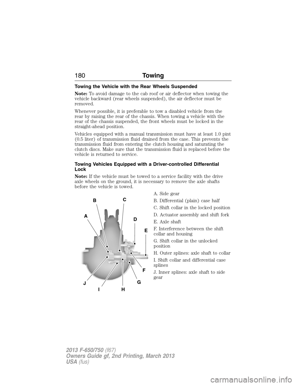
A. Side gear
B. Differential (plain) case half
C. Shift collar in the locked position
D. Actuator assembly and shift fork
E. Axle shaft
F. Interference between the shift
collar and housing
G. Shift collar in the unlocked
position
H. Outer splines: axle shaft to collar
I. Shift collar and differential case
splines
J. Inner splines: axle shaft to side
gear
E
D
CB
A
J
IH
G
F
180Towing
2013 F-650/750(f67)
Owners Guide gf, 2nd Printing, March 2013
USA(fus)
Page 182 of 378
Removing Axle Shafts before Towing
1. Shift the main differential to the unlocked (disengaged) position; the
differential lock light turns off.
2. Remove the capscrews and washers or stud nuts and washers from
flanges of both axle shafts.
3. Loosen the tapered dowels in the flanges of both axle shafts by
holding a 1
1�2inch diameter brass drift or hammer against the axle
shaft center and hitting it with a five or six pound hammer.Note:Do
not use a chisel or wedge to loosen the axle shafts and dowels. Use
of a chisel or wedge can damage the hub, axle shafts and oil seals.
4. Remove the tapered dowels and both axle shafts from the axle
assembly.
5. Assemble a cover over openings of both wheel ends to prevent loss of
lubricant and keep dirt away from the wheel bearing cavities.
Note:One of the axle shafts has two sets of splines. One set to engage
with the differential side gear and one set to engage with the shift collar
for the differential lock. It may be necessary to rotate the shaft slightly
to align the gear spline teeth with the shift collar teeth in order to
remove the axle shaft.
Installing the Axle Shafts
1. Remove the covers from the wheel ends.
2. Shift the differential lock to the unlocked (disengaged) position.
3. Install the axle shafts.
•Place the gaskets on the wheel hub studs.
•Push the right-hand axle shaft and gasket into the wheel end and
housing until the shaft stops against the differential shift collar.
•Push down and in on the axle shaft flange and rotate the shaft
until the splines of the shaft and shift collar are engaged.
•Push the axle shaft further into the housing until the shaft stops
against the differential side gear.
•Push down on the axle shaft flange and rotate the shaft until the
splines of the shaft and side gear are engaged.
•Push the axle shaft completely into the housing until the axle
shaft flange and the gasket are flush against the wheel hub.
•Install the left-hand axle shaft and gasket into the wheel end.
4. If tapered dowels are required, install them at each stud and into the
flange of the axle shaft. Use a punch or drift and hammer, if needed.
5. Install the fasteners and tighten to correct torque value. See the
Workshop Manual.
Towing181
2013 F-650/750(f67)
Owners Guide gf, 2nd Printing, March 2013
USA(fus)
Page 183 of 378
BREAKING-IN
You need to break in new tires for approximately 300 miles
(480 kilometers). During this time, your vehicle may exhibit some unique
driving characteristics. Avoid driving too fast during the first 1000 miles
(1600 kilometers). Vary your speed frequently and change up through
the gears early. Do not labor the engine.
ECONOMICAL DRIVING
Fuel economy is affected by several things such as how you drive, the
conditions you drive under and how you maintain your vehicle.
There are some things to keep in mind that may improve your fuel
economy:
•Accelerate and slow down in a smooth, moderate fashion.
•Drive at steady speeds without stopping.
•Anticipate stops; slowing down may eliminate the need to stop.
•Close the windows for high-speed driving.
•Drive at reasonable speeds (traveling at 55 mph [88 km/h] uses 15%
less fuel than traveling at 65 mph [105 km/h]).
•Keep the tires properly inflated and use only the recommended size.
•Use the recommended engine oil.
•Perform all regularly scheduled maintenance.
There are also some things you may not want to do because they may
reduce your fuel economy:
•Sudden or hard accelerations.
•Warm up your vehicle on cold mornings.
•Use the air conditioner or front defroster.
•Use the speed control in hilly terrain.
•Rest your foot on the brake pedal while driving.
•Carry unnecessary weight (approximately 1 mpg [0.4 km/L] is lost for
every 400 pounds [180 kilograms] of weight carried).
•Add particular accessories to your vehicle (e.g., bug deflectors,
rollbars and light bars, running boards, ski racks).
•Drive with the wheels out of alignment.
182Driving Hints
2013 F-650/750(f67)
Owners Guide gf, 2nd Printing, March 2013
USA(fus)
Page 184 of 378
DRIVING THROUGH WATER
If driving through deep or standing water is unavoidable, proceed very
slowly especially if the depth is not known. Never drive through water
that is higher than the bottom of the hubs. Traction or brake capability
may be limited and your vehicle may stall. Water may also enter your
engine’s air intake and severely damage your engine, drive axles or the
transmission (through the breather ports).
Once through the water, always dry the brakes by moving your vehicle
slowly while applying light pressure on the brake pedal. Wet brakes do
not stop the vehicle as quickly as dry brakes.
Driving Hints183
2013 F-650/750(f67)
Owners Guide gf, 2nd Printing, March 2013
USA(fus)
Page 185 of 378
ROADSIDE ASSISTANCE
Vehicles Sold in the U.S.: Getting Roadside Assistance
To fully assist you should you have a vehicle concern, Ford Motor
Company offers a complimentary roadside assistance program. This
program is separate from the New Vehicle Limited Warranty and is not
applicable to vehicles sold in Canada. The services are available:
•24-hours, seven days a week
•for the New Vehicle Limited Warranty period (U.S.) of two years
(unlimited miles).
Roadside assistance covers:
•battery jump start
•lock-out assistance (Key replacement cost is the customer’s
responsibility.)
•towing – Ford eligible vehicles towed to an authorized dealer within
35 miles (56 kilometers) of the disablement location or to the nearest
authorized dealer. If a member requests to be towed to an authorized
dealer more than 35 miles (56 kilometers) from the disablement
location, the member shall be responsible for any mileage costs in
excess of 35 miles (56 kilometers).
Trailers shall be covered up to $200 if the disabled eligible vehicle
requires service at the nearest authorized dealer. If the trailer is disabled,
but the towing vehicle is operational, the trailer does not qualify for any
roadside services.
Vehicles Sold in the U.S.: Using Roadside Assistance
Complete the roadside assistance identification card and place it in your
wallet for quick reference. This card is found in the owner’s information
portfolio in the glove compartment.
U.S. Ford vehicle customers who require Roadside Assistance, call
1-800-241-3673.
If you need to arrange roadside assistance for yourself, Ford Motor
Company reimburses a reasonable amount for towing to the nearest
dealership within 35 miles (56 kilometers). To obtain reimbursement
information, U.S. Ford vehicle customers call 1-800-241-3673. Customers
are asked to submit their original receipts.
184Roadside Emergencies
2013 F-650/750(f67)
Owners Guide gf, 2nd Printing, March 2013
USA(fus)
Page 186 of 378
Vehicles Sold in Canada: Getting Roadside Assistance
Canadian customers who require roadside assistance, call:
1–800–665–2006.
Vehicles Sold Canada: Using Roadside Assistance
Complete the roadside assistance identification card and place it in your
wallet for quick reference. In Canada, the card is found in the warranty
information in the glove box.
Canadian Roadside coverage and benefits may differ from the U.S.
coverage. Please see your warranty information or visit our website at
www.ford.ca for information on Canadian services and benefits.
Canadian customers who need to obtain roadside information, call
1-800-665-2006 or visit our website at www.ford.ca.
HAZARD FLASHER CONTROL
Note:With extended use, the flasher may run down your battery.
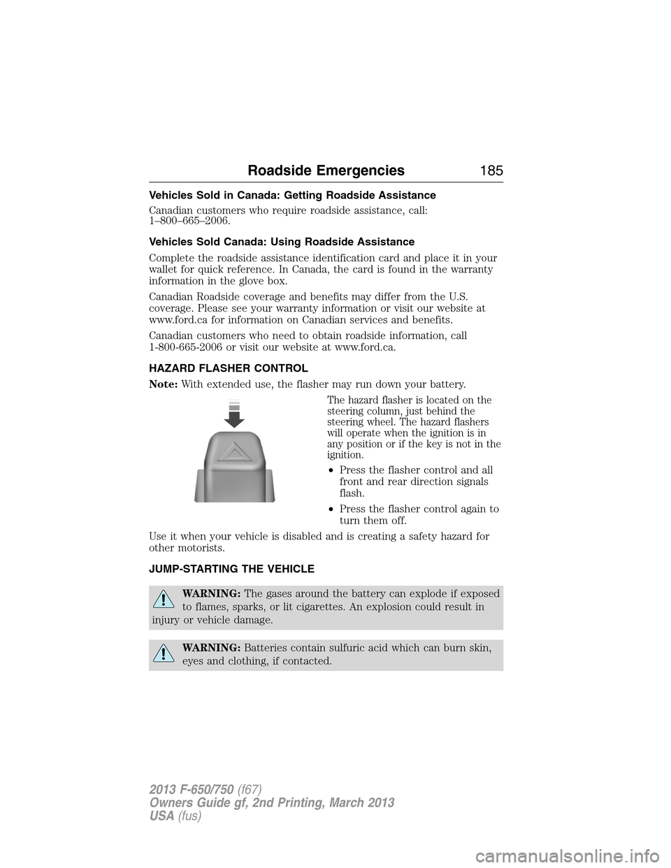
The hazard flasher is located on the
steering column, just behind the
steering wheel. The hazard flashers
will operate when the ignition is in
any position or if the key is not in the
ignition.
•Press the flasher control and all
front and rear direction signals
flash.
•Press the flasher control again to
turn them off.
Use it when your vehicle is disabled and is creating a safety hazard for
other motorists.
JUMP-STARTING THE VEHICLE
WARNING:The gases around the battery can explode if exposed
to flames, sparks, or lit cigarettes. An explosion could result in
injury or vehicle damage.
WARNING:Batteries contain sulfuric acid which can burn skin,
eyes and clothing, if contacted.
Roadside Emergencies185
2013 F-650/750(f67)
Owners Guide gf, 2nd Printing, March 2013
USA(fus)
Page 187 of 378
Do not attempt to push-start your automatic transmission vehicle.
Automatic transmissions do not have push-start capability. Attempting to
push-start a vehicle with an automatic transmission may cause
transmission damage.
Six-speed TorqShift® transmissions have an adaptive shift strategy.
When the battery is disconnected or a new battery is installed, the
automatic transmission must relearn its shift strategy. As a result, the
transmission may have firm soft shifts, firm shifts or both. This operation
is considered normal and does not affect function or durability of the
transmission. Over time, the adaptive learning process fully updates
transmission operation.
Preparing Your Vehicle
Note:Use only a 12–volt supply to start your vehicle.
Note:Do not disconnect the battery of the disabled vehicle as this could
damage the vehicle’s electrical system.
1. Park the booster vehicle close to the hood of the disabled vehicle
making sure the two vehicles do not touch. Set the parking brake on
both vehicles and stay clear of the engine cooling fan and other
moving parts.
2. Check all battery terminals and remove any excessive corrosion
before you attach the battery cables. Make sure that vent caps are
tight and level.
3. Turn the heater fan on in both vehicles to protect from any electrical
surges. Turn all other accessories off.
Connecting the Jumper Cables
WARNING:Do not connect the end of the second cable to the
negative (-) terminal of the battery to be jumped. A spark may
cause an explosion of the gases that surround the battery.
Note:Do not attach the negative (-) cable to fuel lines, engine rocker
covers, the intake manifold or electrical components as grounding points.
Note:In the illustration, the vehicle on the bottom is used to designate
the assisting (boosting) battery.
186Roadside Emergencies
2013 F-650/750(f67)
Owners Guide gf, 2nd Printing, March 2013
USA(fus)
Page 188 of 378
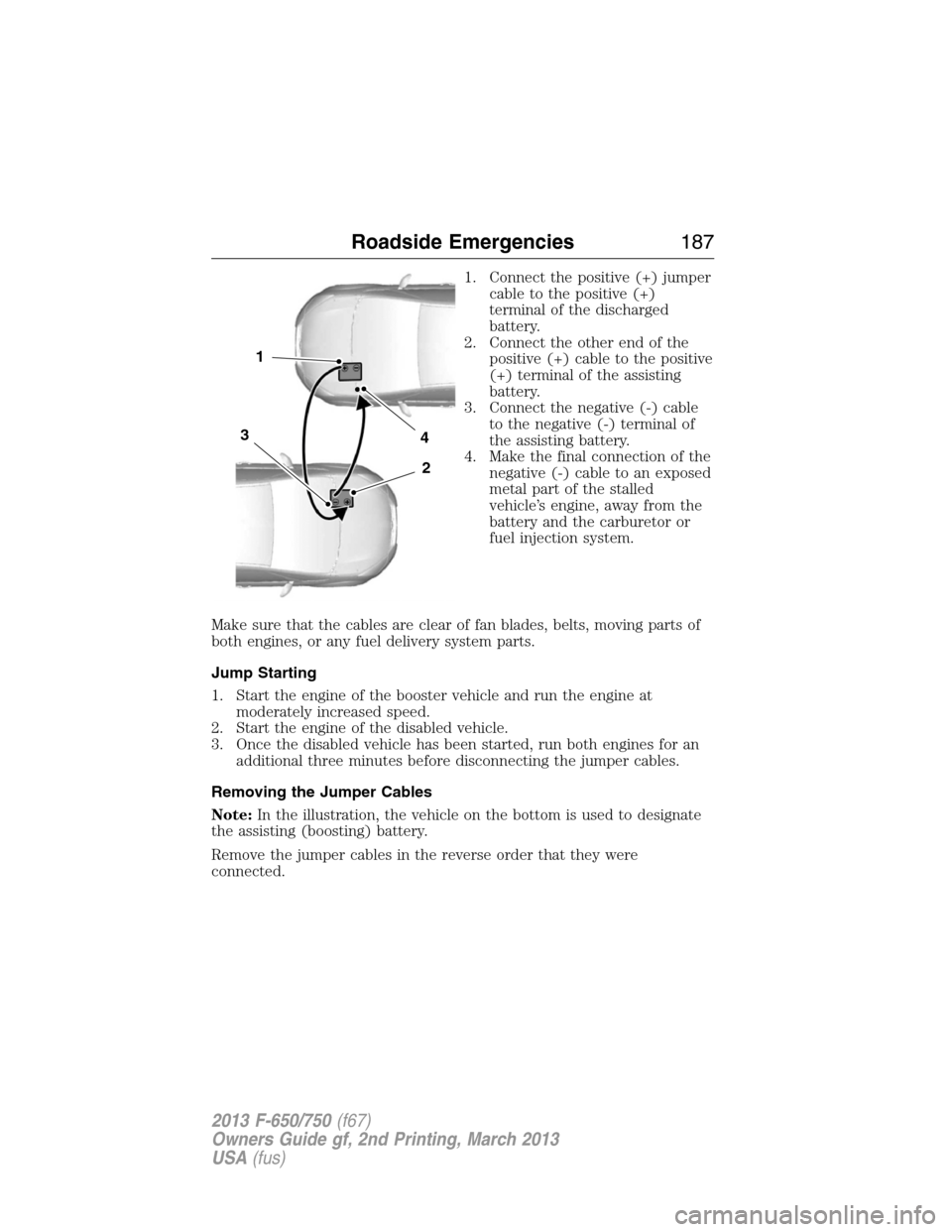
1. Connect the positive (+) jumper
cable to the positive (+)
terminal of the discharged
battery.
2. Connect the other end of the
positive (+) cable to the positive
(+) terminal of the assisting
battery.
3. Connect the negative (-) cable
to the negative (-) terminal of
the assisting battery.
4. Make the final connection of the
negative (-) cable to an exposed
metal part of the stalled
vehicle’s engine, away from the
battery and the carburetor or
fuel injection system.
Make sure that the cables are clear of fan blades, belts, moving parts of
both engines, or any fuel delivery system parts.
Jump Starting
1. Start the engine of the booster vehicle and run the engine at
moderately increased speed.
2. Start the engine of the disabled vehicle.
3. Once the disabled vehicle has been started, run both engines for an
additional three minutes before disconnecting the jumper cables.
Removing the Jumper Cables
Note:In the illustration, the vehicle on the bottom is used to designate
the assisting (boosting) battery.
Remove the jumper cables in the reverse order that they were
connected.
4
2
1
3
Roadside Emergencies187
2013 F-650/750(f67)
Owners Guide gf, 2nd Printing, March 2013
USA(fus)
Page 189 of 378
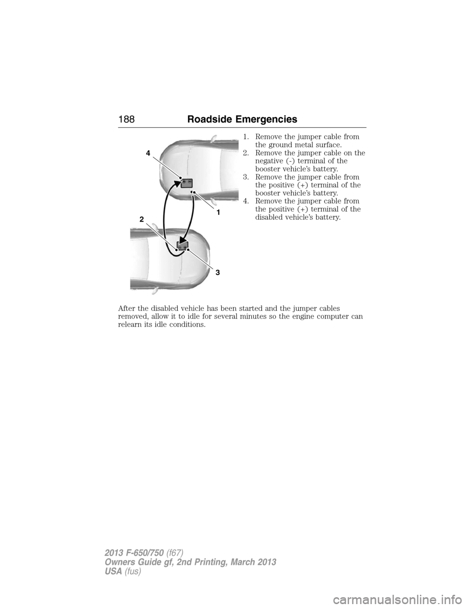
1. Remove the jumper cable from
the ground metal surface.
2. Remove the jumper cable on the
negative (-) terminal of the
booster vehicle’s battery.
3. Remove the jumper cable from
the positive (+) terminal of the
booster vehicle’s battery.
4. Remove the jumper cable from
the positive (+) terminal of the
disabled vehicle’s battery.
After the disabled vehicle has been started and the jumper cables
removed, allow it to idle for several minutes so the engine computer can
relearn its idle conditions.
4
1
3
2
188Roadside Emergencies
2013 F-650/750(f67)
Owners Guide gf, 2nd Printing, March 2013
USA(fus)
Page 190 of 378
GETTING THE SERVICES YOU NEED
Warranty repairs to your vehicle must be performed by an authorized
Ford dealer. While any authorized dealer handling your vehicle line will
provide warranty service, we recommend that you return to your
authorized selling dealer to ensure your continued satisfaction.
Please note that certain warranty repairs require special training or
equipment, so not all authorized dealers are authorized to perform all
warranty repairs. This means that, depending on the warranty repair
needed, you may need to take your vehicle to another authorized dealer.
If you have questions or concerns, or are unsatisfied with the service you
are receiving, follow these steps:
1. Contact your Sales Representative or Service Advisor at your selling
or servicing dealership.
2. If your inquiry or concern remains unresolved, contact the Sales
Manager or Service Manager at the dealership.
3. If the inquiry or concern cannot be resolved at the dealership level,
contact the Ford Commercial Vehicle Operations Hotline. Please have
the following information available:
•Vehicle Identification Number (VIN)
•your telephone number (home and business)
•the name of the authorized dealer and city where located
•the vehicle’s current odometer reading.
In some states, you must directly notify Ford in writing before pursuing
remedies under your state’s warranty laws. Ford is also allowed a final
repair attempt in some states.
In the United States:
Mailing address
Ford Motor Company
Commercial Vehicle Operations
PO Box 6248
Dearborn, MI 48121
Telephone
800-782-8627 (option #3)
(TDD for the hearing impaired: 1-800-232-5952)
Online
Additional information and resources are available online at
www.fleet.ford.com:
•U.S. dealer locator by Dealer Name, City/State, or Zip Code
•Owner Guides
•Maintenance Schedules
Customer Assistance189
2013 F-650/750(f67)
Owners Guide gf, 2nd Printing, March 2013
USA(fus)