FORD FESTIVA 1991 Workshop Manual
Manufacturer: FORD, Model Year: 1991, Model line: FESTIVA, Model: FORD FESTIVA 1991Pages: 454, PDF Size: 9.53 MB
Page 51 of 454
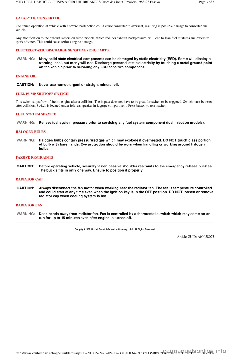
CATALYTIC CONVERTER
Continued operation of vehicle with a severe malfunction could cause converter to overheat, resulting in possible damage to converter and
ve h ic l e .
Any modification to the exhaust system on turbo models, which reduces exhaust backpressure, will lead to lean fuel mixtures and excessive
spark advance. This could cause serious engine damage.
ELECTROSTATIC DISCHARGE SENSITIVE (ESD) PARTS
ENGINE OIL
FUEL PUMP SHUTOFF SWITCH
This switch stops flow of fuel to engine after a collision. The impact does not have to be great for switch to be triggered. Switch must be reset
after collision. Switch is located under left rear speaker in luggage compartment. Press button to reset switch.
FUEL SYSTEM SERVICE
HALOGEN BULBS
PASSIVE RESTRAINTS
RADIATOR CAP
RADIATOR FAN WARNING:Many solid state electrical com ponents can be dam aged by static electricity (ESD). Som e will display a
warning label, but m any will not. Discharge personal static electricity by touching a m etal ground point
on the vehicle prior to servicing any ESD sensitive com ponent.
CAUT ION: Never use non-detergent or straight m ineral oil.
WARNING:Relieve fuel system pressure prior to servicing any fuel system com ponent (fuel injection m odels).
WARNING:Halogen bulbs contain pressurized gas which m ay explode if overheated. DO NOT touch glass portion
of bulb with bare hands. Eye protection should be worn when handling or working around halogen
bulbs.
CAUT ION: Before operating vehicle, securely fasten passive shoulder restraints to the em ergency release buckles.
T he buckle fits in only one way. Ensure to position it properly.
CAUT ION: Always disconnect the fan m otor when working near the radiator fan. T he fan is tem perature controlled
and could start at any tim e even when the ignition key is in the OFF position. DO NOT loosen or rem ove
radiator cap when cooling system is hot.
WARNING:Keep hands away from radiator fan. Fan is controlled by a therm ostatic switch which m ay com e on or
run for up to 15 m inutes even after engine is turned off.
Copyr ight 2009 Mitchell Repair Information Company, LLC. All Rights Reserved.
Article GUID: A00058075
Page 3 of 3 MITCHELL 1 ARTICLE - FUSES & CIRCUIT BREAKERS Fuses & Circuit Breakers 1988-93 Festiva
3/10/2009 http://www.eautorepair.net/app/PrintItems.asp?S0=2097152&S1=0&SG=%7B7DD6473C%2DB5BB%2D4F20%2D9D70%2D
...
Page 52 of 454
Back To Article
ST ART ER
1991 ELECT RICAL Starters
DESCRIPTION
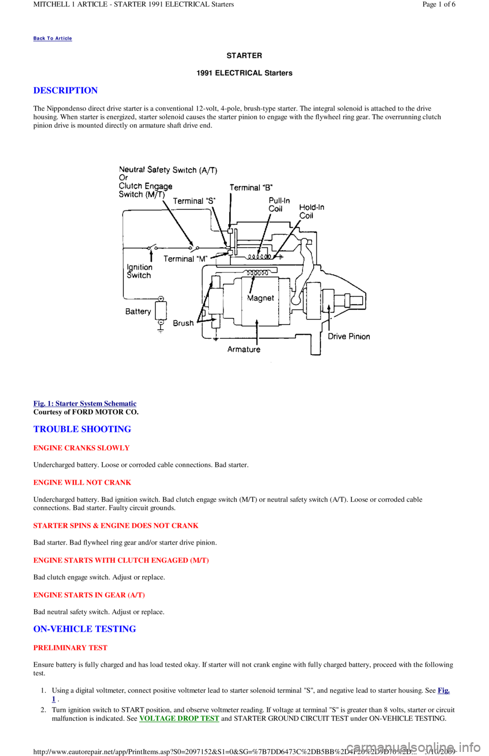
The Nippondenso direct drive starter is a conventional 12-volt, 4-pole, brush-type starter. The integral solenoid is attached to the drive
housing. When starter is energized, starter solenoid causes the starter pinion to engage with the flywheel ring gear. The overrunning clutch
pinion drive is mounted directly on armature shaft drive end.
Fig. 1: Starter System Schematic
Courtesy of FORD MOTOR CO.
TROUBLE SHOOTING
ENGINE CRANKS SLOWLY
Undercharged battery. Loose or corroded cable connections. Bad starter.
ENGINE WILL NOT CRANK
Undercharged battery. Bad ignition switch. Bad clutch engage switch (M/T) or neutral safety switch (A/T). Loose or corroded cable
connections. Bad starter. Faulty circuit grounds.
STARTER SPINS & ENGINE DOES NOT CRANK
Bad starter. Bad flywheel ring gear and/or starter drive pinion.
ENGINE STARTS WITH CLUTCH ENGAGED (M/T)
Bad clutch engage switch. Adjust or replace.
ENGINE STARTS IN GEAR (A/T)
Bad neutral safety switch. Adjust or replace.
ON-VEHICLE TESTING
PRELIMINARY TEST
Ensure battery is fully charged and has load tested okay. If starter will not crank engine with fully charged battery, proceed with the following
test.
1. Using a digital voltmeter, connect positive voltmeter lead to starter solenoid terminal "S", and negative lead to starter housing. See Fig.
1 .
2. Turn ignition switch to START position, and observe voltmeter reading. If voltage at terminal "S" is greater than 8 volts, starter or circuit
malfunction is indicated. See VOLTAGE DROP TEST
and STARTER GROUND CIRCUIT TEST under ON-VEHICLE TESTING.
Page 1 of 6 MITCHELL 1 ARTICLE - STARTER 1991 ELECTRICAL Starters
3/10/2009 http://www.eautorepair.net/app/PrintItems.asp?S0=2097152&S1=0&SG=%7B7DD6473C%2DB5BB%2D4F20%2D9D70%2D
...
Page 53 of 454
3. If voltage is not present or is less than 8 volts at starter solenoid terminal "S", malfunction in circuit to terminal "S" is indicated. Proceed
to the following tests.
IGNITION SWITCH TEST
1. Locate ignition switch connector under dash. Using a 12-volt test light or voltmeter, ensure voltage is present on Black/Yellow wire
when ignition switch is turned to RUN or ON position. This will verify proper operation of ignition switch.
2. If there is no voltage on Black/Yellow wire, the problem is either ignition switch or circuit between battery and ignition switch.
CLUTCH ENGAGE SWITCH (M/T) TEST
Unplug clutch engage switch from main wiring harness. Using an ohmmeter, check for continuity across switch terminals. Continuity should
exist when switch plunger is pushed in and should not exist when switch plunger is released. If clutch engage switch does not operate as
specified, replace switch.
NEUTRAL SAFETY SWITCH (A/T) TEST
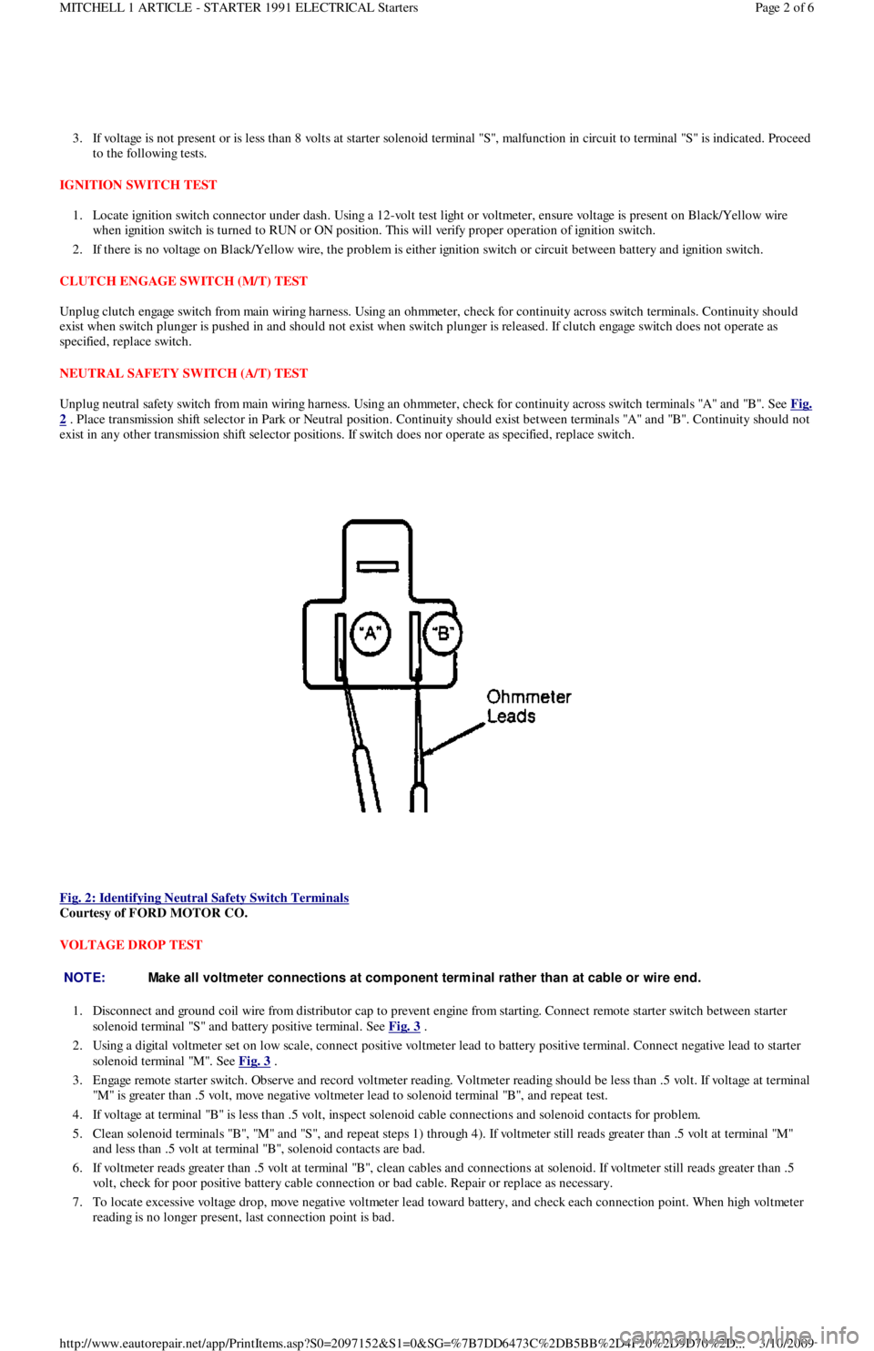
Unplug neutral safety switch from main wiring harness. Using an ohmmeter, check for continuity across switch terminals "A" and "B". See Fig.
2 . Place transmission shift selector in Park or Neutral position. Continuity should exist between terminals "A" and "B". Continuity should not
exist in any other transmission shift selector positions. If switch does nor operate as specified, replace switch.
Fig. 2: Identifying Neutral Safety Switch Terminals
Courtesy of FORD MOTOR CO.
VOLTAGE DROP TEST
1. Disconnect and ground coil wire from distributor cap to prevent engine from starting. Connect remote starter switch between starter
solenoid terminal "S" and battery positive terminal. See Fig. 3
.
2. Using a digital voltmeter set on low scale, connect positive voltmeter lead to battery positive terminal. Connect negative lead to starter
solenoid terminal "M". See Fig. 3
.
3. Engage remote starter switch. Observe and record voltmeter reading. Voltmeter reading should be less than .5 volt. If voltage at terminal
"M" is greater than .5 volt, move negative voltmeter lead to solenoid terminal "B", and repeat test.
4. If voltage at terminal "B" is less than .5 volt, inspect solenoid cable connections and solenoid contacts for problem.
5 . Cl ean so l en o id t ermin al s "B", "M" an d "S", an d rep eat st ep s 1 ) through 4). If voltmeter still reads greater than .5 volt at termin al "M"
and less than .5 volt at terminal "B", solenoid contacts are bad.
6. If voltmeter reads greater than .5 volt at terminal "B", clean cables and connections at solenoid. If voltmeter still reads greater than .5
volt, check for poor positive battery cable connection or bad cable. Repair or replace as necessary.
7. To locate excessive voltage drop, move negative voltmeter lead toward battery, and check each connection point. When high voltmeter
reading is no longer present, last connection point is bad.
NOTE:Make all voltm eter connections at com ponent term inal rather than at cable or wire end.
Page 2 of 6 MITCHELL 1 ARTICLE - STARTER 1991 ELECTRICAL Starters
3/10/2009 http://www.eautorepair.net/app/PrintItems.asp?S0=2097152&S1=0&SG=%7B7DD6473C%2DB5BB%2D4F20%2D9D70%2D
...
Page 54 of 454
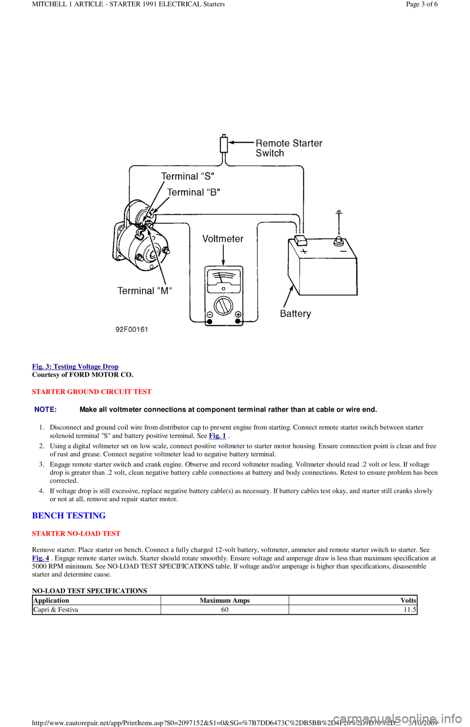
Fig. 3: Testing Voltage Drop
Courtesy of FORD MOTOR CO.
STARTER GROUND CIRCUIT TEST
1. Disconnect and ground coil wire from distributor cap to prevent engine from starting. Connect remote starter switch between starter
solenoid terminal "S" and battery positive terminal. See Fig. 1
.
2. Using a digital voltmeter set on low scale, connect positive voltmeter to starter motor housing. Ensure connection point is clean and free
of rust and grease. Connect negative voltmeter lead to negative battery terminal.
3. Engage remote starter switch and crank engine. Observe and record voltmeter reading. Voltmeter should read .2 volt or less. If voltage
drop is greater than .2 volt, clean negative battery cable connections at battery and body connections. Retest to ensure problem has been
corrected.
4. If voltage drop is still excessive, replace negative battery cable(s) as necessary. If battery cables test okay, and starter still cranks slowly
or not at all, remove and repair starter motor.
BENCH TESTING
STARTER NO-LOAD TEST
Remove starter. Place starter on bench. Connect a fully charged 12-volt battery, voltmeter, ammeter and remote starter switch to starter. See
Fig. 4
. Engage remote starter switch. Starter should rotate smoothly. Ensure voltage and amperage draw is less than maximum specification at
5000 RPM minimum. See NO-LOAD TEST SPECIFICATIONS table. If voltage and/or amperage is higher than specifications, disassemble
starter and determine cause.
NO-LOAD TEST SPECIFICATIONS
NOTE:Make all voltm eter connections at com ponent term inal rather than at cable or wire end.
ApplicationMaximum AmpsVolts
Capri & Festiva6011.5
Page 3 of 6 MITCHELL 1 ARTICLE - STARTER 1991 ELECTRICAL Starters
3/10/2009 http://www.eautorepair.net/app/PrintItems.asp?S0=2097152&S1=0&SG=%7B7DD6473C%2DB5BB%2D4F20%2D9D70%2D
...
Page 55 of 454
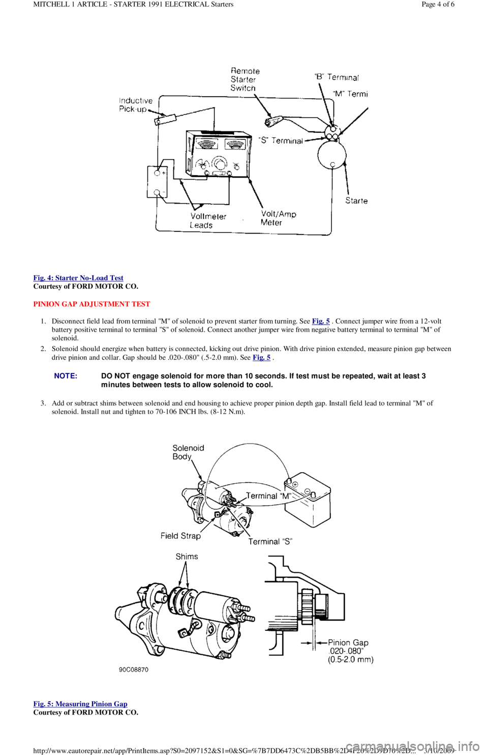
Fig. 4: Starter No
-Load Test
Courtesy of FORD MOTOR CO.
PINION GAP ADJUSTMENT TEST
1. Disconnect field lead from terminal "M" of solenoid to prevent starter from turning. See Fig. 5
. Connect jumper wire from a 12-volt
battery positive terminal to terminal "S" of solenoid. Connect another jumper wire from negative battery terminal to terminal "M" of
solenoid.
2. Solenoid should energize when battery is connected, kicking out drive pinion. With drive pinion extended, measure pinion gap between
drive pinion and collar. Gap should be .020-.080" (.5-2.0 mm). See Fig. 5
.
3. Add or subtract shims between solenoid and end housing to achieve proper pinion depth gap. Install field lead to terminal "M" of
solenoid. Install nut and tighten to 70-106 INCH lbs. (8-12 N.m).
Fig. 5: Measuring Pinion Gap
Courtesy of FORD MOTOR CO.
NOTE:DO NOT engage solenoid for m ore than 10 seconds. If test m ust be repeated, wait at least 3
m inutes between tests to allow solenoid to cool.
Page 4 of 6 MITCHELL 1 ARTICLE - STARTER 1991 ELECTRICAL Starters
3/10/2009 http://www.eautorepair.net/app/PrintItems.asp?S0=2097152&S1=0&SG=%7B7DD6473C%2DB5BB%2D4F20%2D9D70%2D
...
Page 56 of 454
SOLENOID TEST
Disconnect wiring and cables from solenoid. Using an ohmmeter, check for continuity between terminal "M" and body of starter solenoid. See
Fig. 1
. Continuity should exist. If continuity does not exist, replace solenoid.
ARMATURE TEST
1. Place armature in growler. Turn on growler and hold a piece of hacksaw blade over armature. Slowly rotate armature. If hacksaw blade
is attracted to core or if it vibrates, replace armature.
2. Remove armature from growler. Using an ohmmeter, check continuity between commutator and core. If continuity exists, replace
armature. Check continuity between commutator and shaft. If continuity exists, replace armature.
3. Check continuity between each commutator segment. If an open exists between any 2 segments, replace armature.
COMMUTATOR TEST
1. Clean surface of commutator and polish with No. 400 grit sandpaper (if required). If surface is scored, out of round or pitted, turn
commutator on a lathe.
2. Maximum commutator runout and minimum diameter of commutator must not exceed specification after turning. See STARTER
MOTOR SPECIFICATIONS table.
3. Commutator mica undercut depth should be .02-.03" (.5-.8 mm). If undercut depth is not within specification, undercut with a hacksaw
blade to standard depth.
BRUSH & SPRING TEST
1. Connect ohmmeter between positive brush holder and negative brush holder. If ohmmeter indicates continuity, brush holder assemb l y is
shorted and must be replaced.
2. Check brush length. See STARTER MOTOR SPECIFICATIONS
table. If brush length is less than specification, replace brushes.
3. Check spring tension. Spring tension should be 2.0-4.3 Lbs. (8.8-19.1 N.m). Ensure brushes move freely in holders.
FIELD COIL TEST
1. Connect ohmmeter between field lead and soldered portion of brush lead. If continuity does not exist, repair or replace field coil.
2. Check field coil for shorts to ground by connecting ohmmeter between field lead and starter housing. If continuity exists, repair or
replace field coil.
OVERHAUL
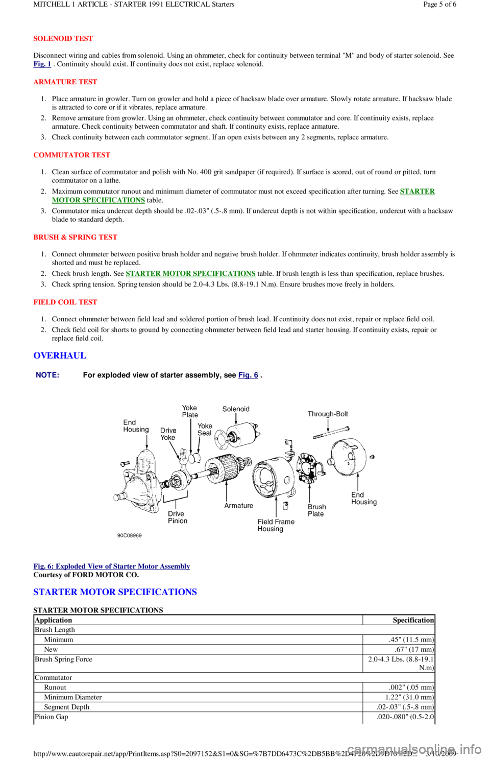
Fig. 6: Exploded View of Starter Motor Assembly
Courtesy of FORD MOTOR CO.
STARTER MOTOR SPECIFICATIONS
STARTER MOTOR SPECIFICATIONS NOTE:For exploded view of starter assem bly, see Fig. 6
.
ApplicationSpecification
Brush Length
Minimum.45" (11.5 mm)
New.67" (17 mm)
Brush Spring Force2.0-4.3 Lbs. (8.8-19.1
N.m)
Commutator
Runout.002" (.05 mm)
Min imu m Diamet er1.22" (31.0 mm)
Segment Depth.02-.03" (.5-.8 mm)
Pinion Gap.020-.080" (0.5-2.0
Page 5 of 6 MITCHELL 1 ARTICLE - STARTER 1991 ELECTRICAL Starters
3/10/2009 http://www.eautorepair.net/app/PrintItems.asp?S0=2097152&S1=0&SG=%7B7DD6473C%2DB5BB%2D4F20%2D9D70%2D
...
Page 57 of 454
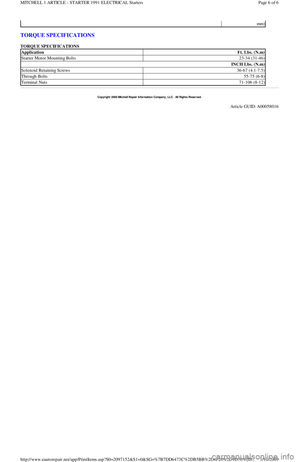
TORQUE SPECIFICATIONS
TORQUE SPECIFICATIONS
mm)
ApplicationFt. Lbs. (N.m)
Starter Motor Mounting Bolts23-34 (31-46)
INCH Lbs. (N.m)
Solenoid Retaining Screws36-67 (4.1-7.5)
Through Bolts55-75 (6-8)
Terminal Nuts71-106 (8-12)
Copyr ight 2009 Mitchell Repair Information Company, LLC. All Rights Reserved.
Article GUID: A00058016
Page 6 of 6 MITCHELL 1 ARTICLE - STARTER 1991 ELECTRICAL Starters
3/10/2009 http://www.eautorepair.net/app/PrintItems.asp?S0=2097152&S1=0&SG=%7B7DD6473C%2DB5BB%2D4F20%2D9D70%2D
...
Page 58 of 454
Back To Article
1991 System Wiring Diagram s
Ford - Festiva
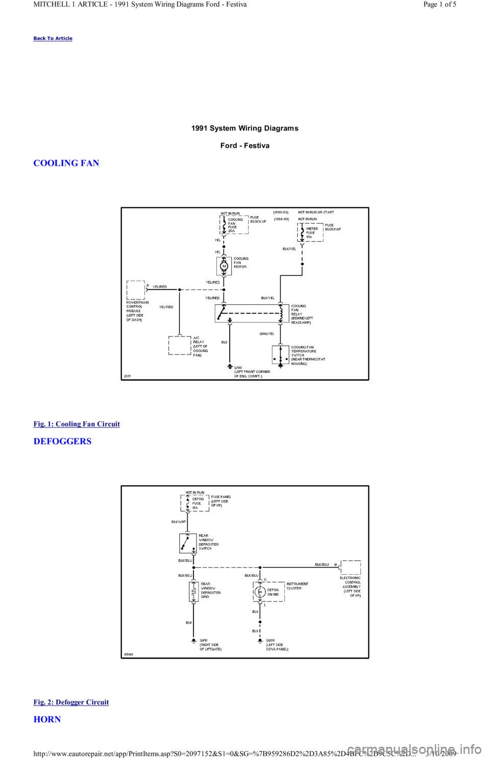
COOLING FAN
Fig. 1: Cooling Fan Circuit
DEFOGGERS
Fig. 2: Defogger Circuit
HORN
Page 1 of 5 MITCHELL 1 ARTICLE - 1991 System Wiring Diagrams Ford - Festiva
3/10/2009 http://www.eautorepair.net/app/PrintItems.asp?S0=2097152&S1=0&SG=%7B959286D2%2D3A85%2D4BFC%2D9C5C%2D
...
Page 59 of 454
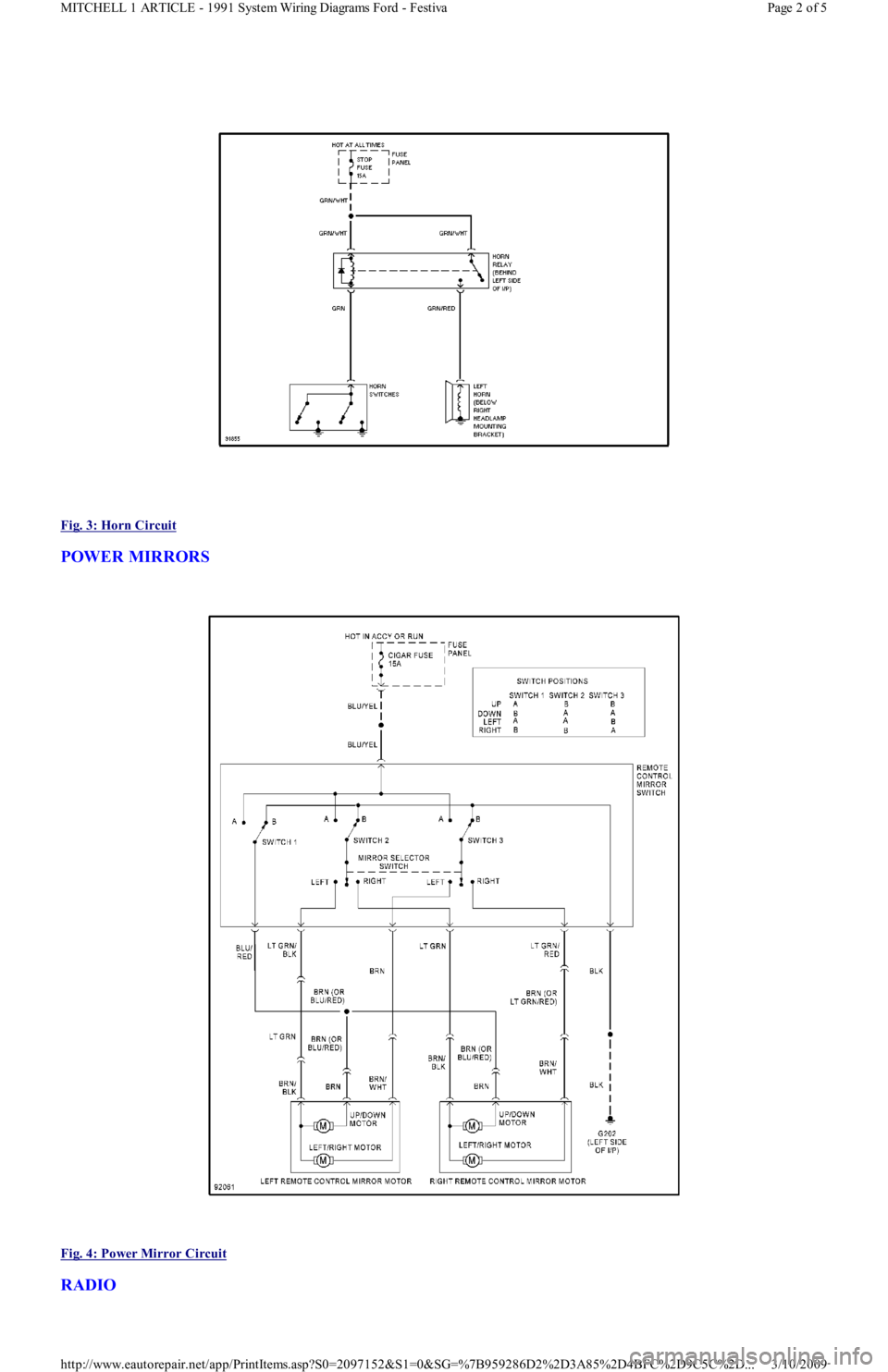
Fig. 3: Horn Circuit
POWER MIRRORS
Fig. 4: Power Mirror Circuit
RADIO
Page 2 of 5 MITCHELL 1 ARTICLE - 1991 System Wiring Diagrams Ford - Festiva
3/10/2009 http://www.eautorepair.net/app/PrintItems.asp?S0=2097152&S1=0&SG=%7B959286D2%2D3A85%2D4BFC%2D9C5C%2D
...
Page 60 of 454
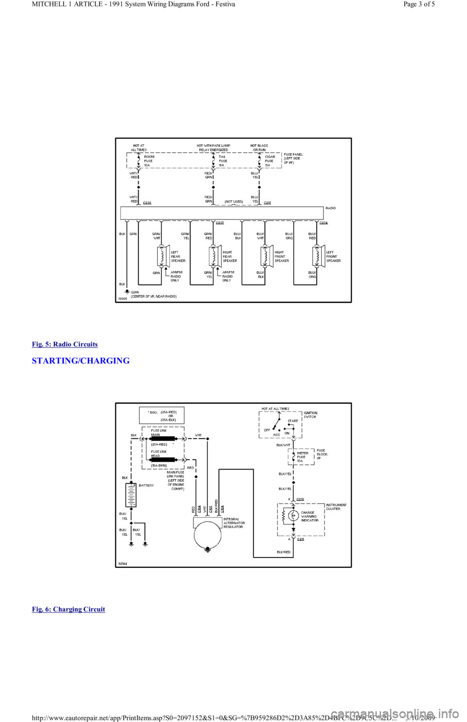
Fig. 5: Radio Circuits
STARTING/CHARGING
Fig. 6: Charging Circuit
Page 3 of 5 MITCHELL 1 ARTICLE - 1991 System Wiring Diagrams Ford - Festiva
3/10/2009 http://www.eautorepair.net/app/PrintItems.asp?S0=2097152&S1=0&SG=%7B959286D2%2D3A85%2D4BFC%2D9C5C%2D
...