FORD FIESTA 2007 Workshop Manual
Manufacturer: FORD, Model Year: 2007, Model line: FIESTA, Model: FORD FIESTA 2007Pages: 1226, PDF Size: 61.26 MB
Page 1131 of 1226
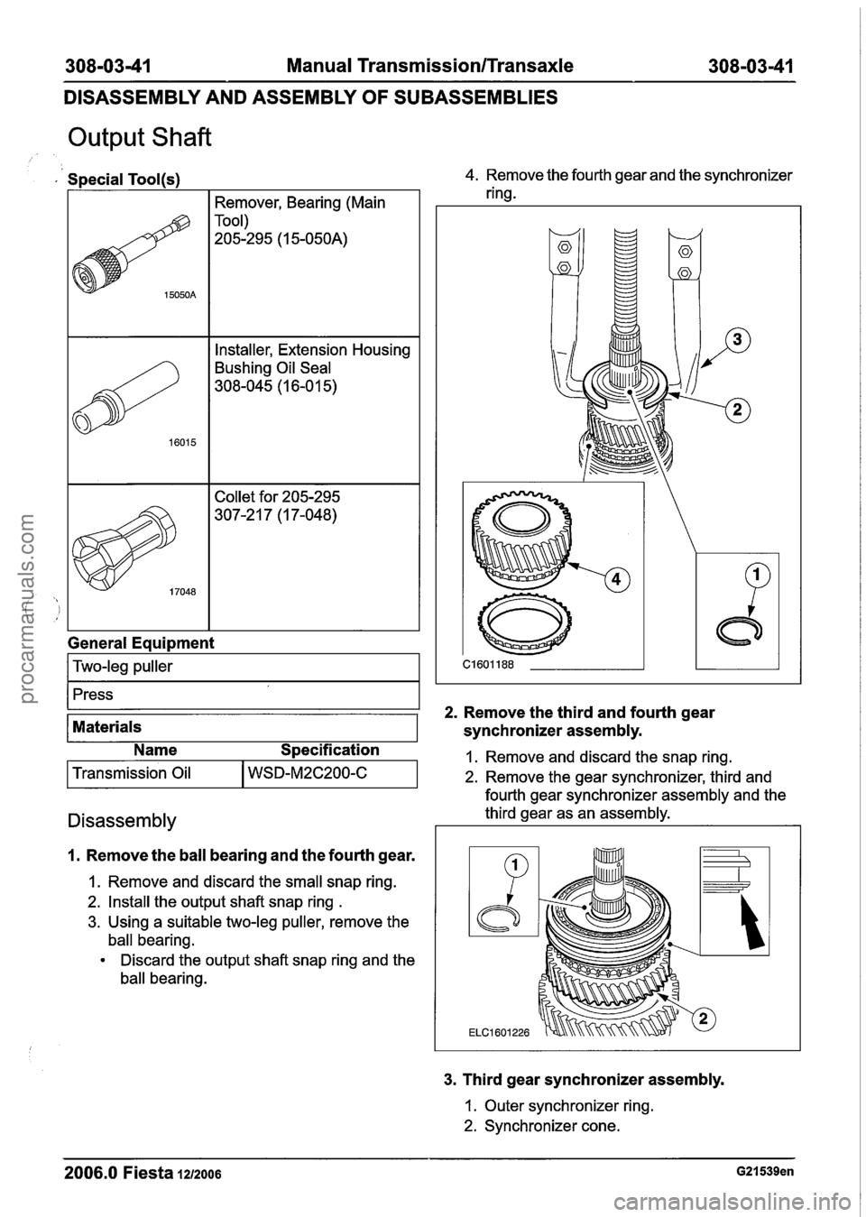
308-0341 Manual Transmission/Transaxle 308-03-41
DISASSEMBLY AND ASSEMBLY
OF SUBASSEMBLIES
Output Shaft
Special Tool(s)
I I Remover, Bearing (Main I
I I Installer, Extension Housing I
Bushing Oil Seal
308-045
(1 6-0 1 5)
General
Eaui~ment
I Two-leg puller I
4. Remove the fourth gear and the synchronizer
ring.
1. Remove the ball bearing and the fourth gear.
Press
2. Remove the
third and fourth gear
1. Remove and discard the small snap ring.
2. Install the output shaft snap ring
.
3. Using a suitable two-leg puller, remove the
ball bearing.
Discard the output shaft snap ring and the
ball bearing.
Materials
3. Third gear synchronizer assembly.
synchronizer assembly.
1. Outer
synchronizer ring.
2. Synchronizer cone.
2006.0 Fiesta 1212006 G21539en
Name Specification I. Remove and discard the snap ring.
2. Remove the gear synchronizer, third and
Transmission
Oil
fourth gear synchronizer assembly and the
Disassembly third gear as an assembly.
WSD-M2C200-C
procarmanuals.com
Page 1132 of 1226
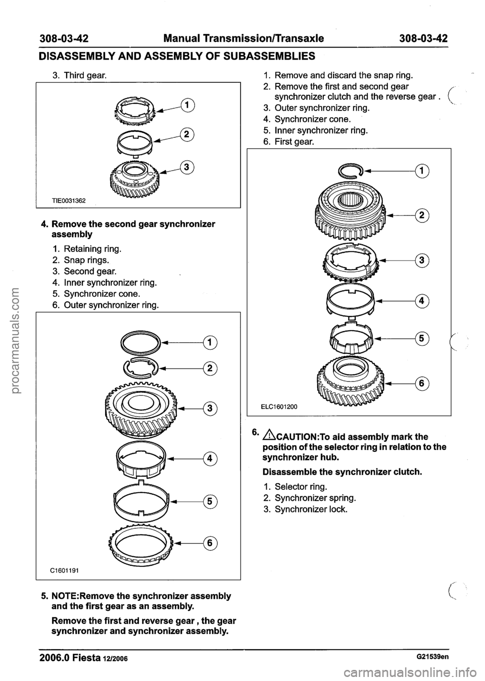
308-03-42 Manual Transmission/Transaxle 308-03-42
DISASSEMBLY AND ASSEMBLY
OF SUBASSEMBLIES
3. Third gear.
4. Remove the second gear synchronizer
assembly
I. Retaining ring.
2. Snap rings.
3. Second gear.
4. lnner synchronizer ring.
5. Synchronizer cone.
6. Outer synchronizer ring.
5. N0TE:Remove the synchronizer assembly
and the first gear as an assembly.
Remove the first and reverse gear, the gear
synchronizer and synchronizer assembly.
1. Remove and discard the snap ring.
2. Remove the first and second gear
synchronizer clutch and the reverse gear
. ( \.. 3. Outer synchronizer ring.
4. Synchronizer cone.
5. lnner synchronizer ring.
6. First gear.
6m ACAUTION:T~ aid assembly mark the
position of the selector ring in relation to the
synchronizer hub.
Disassemble the synchronizer clutch.
I. Selector ring.
2. Synchronizer spring.
3. Synchronizer lock.
--
2006.0 Fiesta 1212006 G21539en
procarmanuals.com
Page 1133 of 1226
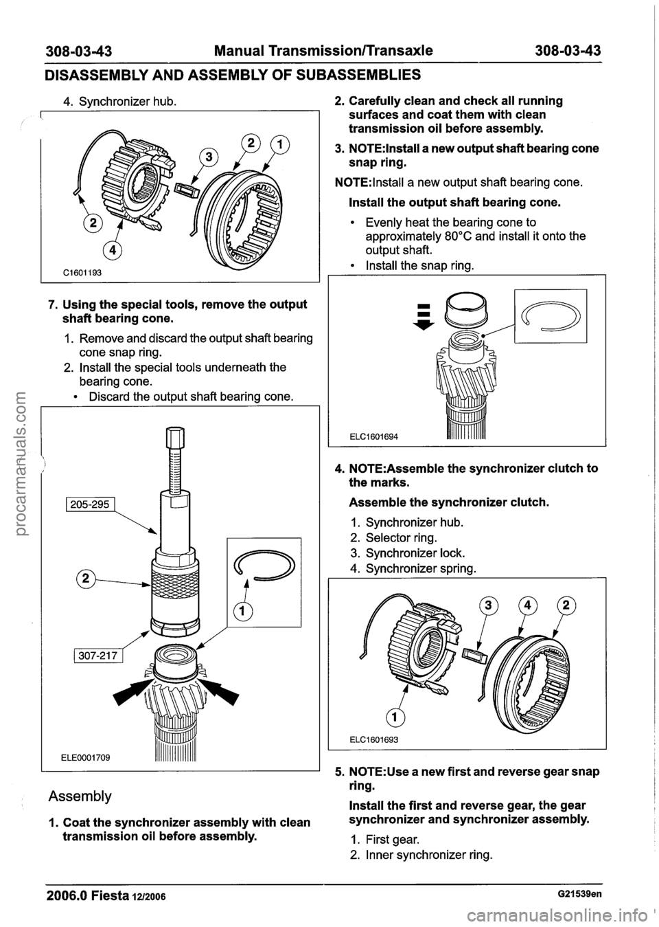
308-0343 Manual TransmissionlTransaxle 308-03-43
DISASSEMBLY AND ASSEMBLY OF SUBASSEMBLIES
4. Synchronizer hub.
7. Using the special tools, remove the output
shaft bearing cone.
1. Remove and discard the output shaft bearing
cone snap ring.
2. Install the special tools underneath the
bearing cone.
Discard the output shaft bearing cone.
Assembly
I. Coat the synchronizer assembly with clean
transmission oil before assembly.
2. Carefully clean and check all running
surfaces and coat them with clean
transmission oil before assembly.
3. N0TE:lnstall a new output shaft bearing cone
snap ring.
N0TE:lnstall a new output shaft bearing cone.
Install the output shaft bearing cone.
Evenly heat the bearing cone to
approximately
80°C and install it onto the
output shaft.
Install the snap ring.
4. N0TE:Assemble the synchronizer clutch to
the marks.
Assemble the synchronizer clutch.
I. Synchronizer hub.
2. Selector ring.
3. Synchronizer lock.
4. Synchronizer spring.
5.
N0TE:Use a new first and reverse gear snap
ring.
Install the first and reverse gear, the gear
synchronizer and synchronizer assembly.
1. First gear.
2. Inner synchronizer ring.
2006.0 Fiesta 1212006 G21539en
procarmanuals.com
Page 1134 of 1226
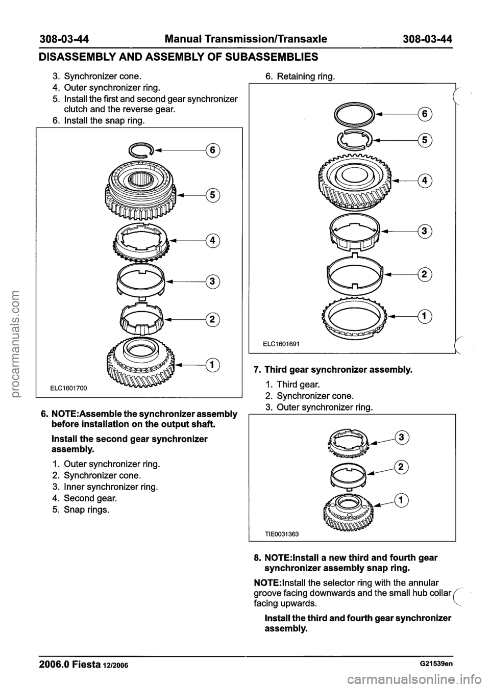
308-03-44 Manual Transmission/Transaxle 308-03-44
DISASSEMBLY AND ASSEMBLY OF SUBASSEMBLIES
3. Synchronizer cone. 6. Retaining ring.
4. Outer synchronizer ring.
5. lnstall the first and second gear synchronizer
clutch and the reverse gear.
6. lnstall the snap ring.
6. N0TE:Assemble the synchronizer assembly
before installation on the output shaft.
lnstall the second gear synchronizer
assembly.
1. Outer synchronizer ring.
2. Synchronizer cone.
3. Inner synchronizer ring.
4. Second gear.
5. Snap rings.
7. Third gear synchronizer assembly.
1. Third gear.
2. Synchronizer cone.
3. Outer synchronizer ring.
8. N0TE:lnstall a new third and fourth gear
synchronizer assembly snap ring.
N0TE:lnstall the selector ring with the annular
groove facing downwards and the small hub collar
facing upwards.
Install the third and fourth gear synchronizer
assembly.
2006.0 Fiesta 1212006 G21539en
procarmanuals.com
Page 1135 of 1226
30810345 Manual Transmission/Transaxle 308103145
DISASSEMBLY AND ASSEMBLY OF SUBASSEMBLIES
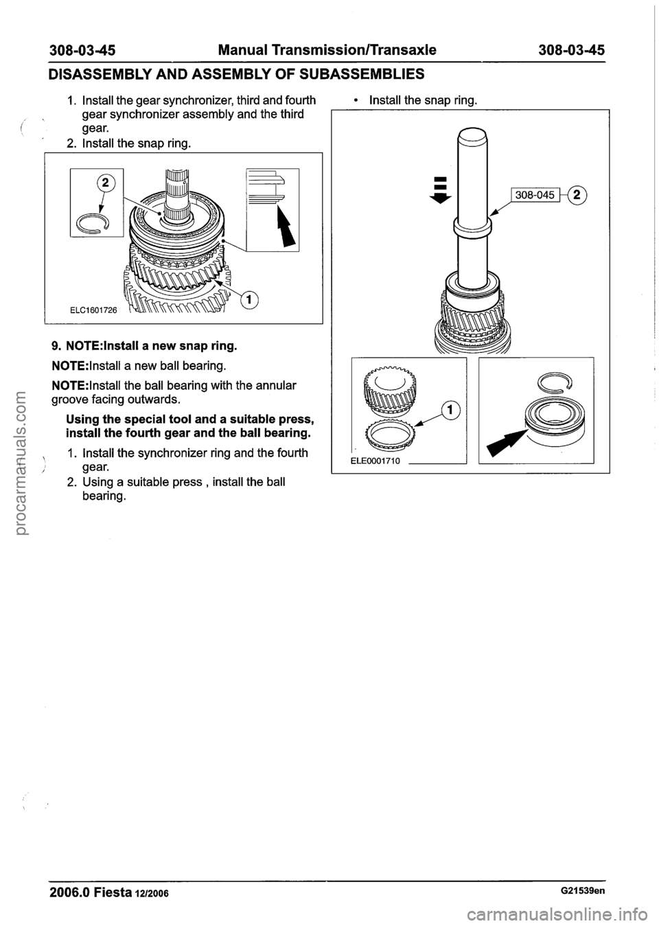
1. Install the gear synchronizer, third and fourth Install the snap ring.
gear synchronizer assembly and the third
(' gear.
2. lnstall the snap ring.
9. N0TE:lnstall a new snap ring.
N0TE:lnstall a new ball bearing.
N0TE:lnstall the ball bearing with the annular
groove facing outwards.
Using the special tool and a suitable press,
install the fourth gear and the ball bearing.
1. lnstall the synchronizer ring and the fourth
( gear.
2. Using a suitable press , install the ball
bearing.
2006.0 Fiesta 1212006 G21539en
procarmanuals.com
Page 1136 of 1226
308-0346 Manual Transmission/Transaxle 308-03-46
DISASSEMBLY AND ASSEMBLY OF SUBASSEMBLIES
Input Shaft
Special Tool(s)
I I Installer, Extension Housing I
BushingIOil Seal
308-045
(1 6-0 1 5)
General Equipment
Two-leg puller
1 press I
Discard the ball bearing.
Materials
Name
S~ecification 1 Assembly
I Transmission Oil I WSD-M2C200-C I
Disassembly
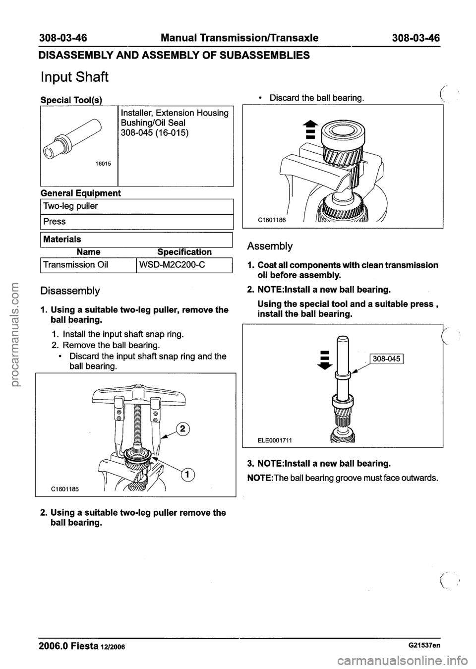
1. Using a suitable two-leg puller, remove the
ball bearing.
1. Install the input shaft snap ring.
2. Remove the ball bearing.
Discard the input shaft snap ring and the
ball bearing.
I. Coat all components with clean transmission
oil before assembly.
2. N0TE:lnstall a new ball bearing.
Using the special tool and a suitable press
,
install the ball bearing.
/-
'.
3. N0TE:lnstall a new ball bearing.
N0TE:The ball bearing groove must face outwards.
2. Using a suitable two-leg puller remove the
ball bearing.
2006.0 Fiesta 1212006 G21537en
procarmanuals.com
Page 1137 of 1226
308-0347 Manual Transmission/Transaxle 308-03-47
DISASSEMBLY AND ASSEMBLY OF SUBASSEMBLIES
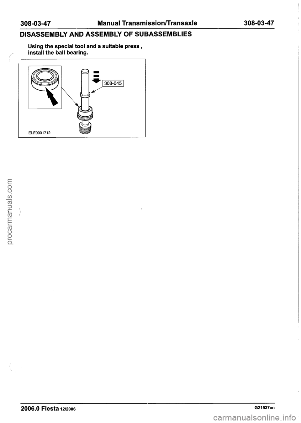
Using the special tool and a suitable press ,
/' install the ball bearing.
--
2006.0 Fiesta 12/2006 G21537en
procarmanuals.com
Page 1138 of 1226

308-0348 Manual TransmissionlTransaxle 308-03-48
General Equipment
1 press I
1 Drift I
Materials
Name
S~ecification
1 Transmission Oil I WSD-M2C200-C I
Disassembly
1. Using the special tools, remove the
differential taper roller bearings.
I. Install the special tool.
2. Remove the differential taper roller bearings.
1. Rotate the differential pinions approximately
90 degrees in the differential case and
remove them.
2. Remove and discard the snap ring and using
a suitable drift, drive out the pin.
Remove the two differential pinions and
plastic thrust elements.
3. Remove the ring gear retaining bolts.
2006.0 Fiesta 1212006 G21541 en
procarmanuals.com
Page 1139 of 1226
308-0349 Manual Transmission/Transaxle 308-03-49
DISASSEMBLY AND ASSEMBLY OF SUBASSEMBLIES
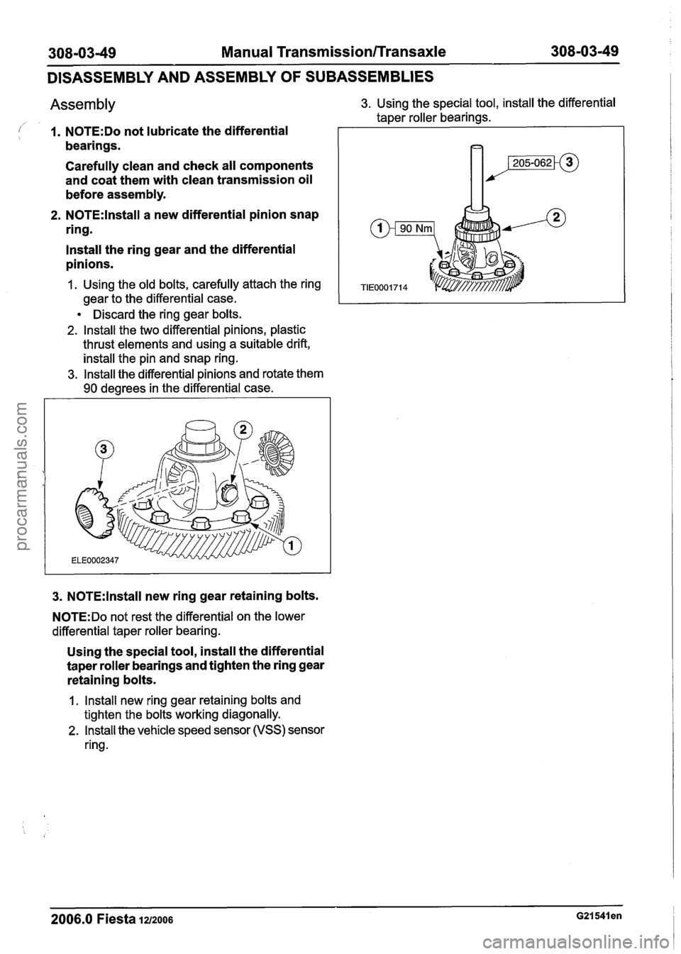
Assembly 3. Using the special tool, install the differential
taper roller bearings.
I 1. N0TE:Do not lubricate the differential
bearings.
Carefully clean and check all components
and coat them with clean transmission oil
before assembly.
2. N0TE:lnstall a new differential pinion snap
ring.
lnstall the ring gear and the differential
pinions.
1. Using the old bolts, carefully attach the ring
gear to the differential case.
1 I
Discard the ring gear bolts.
2. lnstall the two differential pinions, plastic
thrust elements and using a suitable drift,
install the pin and snap ring.
3. lnstall the differential pinions and rotate them
90 degrees in the differential case.
3. N0TE:lnstall new ring gear retaining bolts.
N0TE:Do not rest the differential on the lower
differential taper roller bearing.
Using the special tool, install the differential
taper roller bearings and tighten the ring gear
retaining bolts.
1 . lnstall new ring gear retaining bolts and
tighten the bolts working diagonally.
2. lnstall the vehicle speed sensor (VSS) sensor
ring.
2006.0 Fiesta 1212006 G21541 en
procarmanuals.com
Page 1140 of 1226
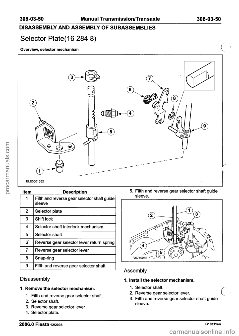
308-03-50 Manual Transmission/Transaxle 308-03-50
DISASSEMBLY AND ASSEMBLY OF SUBASSEMBLIES
Selector Plate(l6 284 8)
Overview, selector mechanism
1 2 1 Selector plate I
Item Description 5. Fifth and reverse gear selector shaft guide
1 4 1 Selector shaft interlock mechanism I
1
1 5 1 Selector shaft I
Fifth and reverse gear selector shaft guide
1 6- 1 Reverse gear selector lever return sleeve.
sleeve
1 7 1 Reverse gear selector lever I
Disassembly
1. Remove the selector mechanism.
8
9
1. Fifth and reverse gear selector shaft.
2. Selector shaft.
3. Reverse gear selector lever .
Snap-ring
Fifth and reverse gear selector shaft
4. Selector plate.
Assembly
1, Install the selector mechanism.
1 . Selector shaft.
2. Reverse gear selector lever.
3. Fifth and reverse gear selector shaft guide
sleeve.
-- - - - -- --
2006.0 Fiesta 1212006 G18lllen
procarmanuals.com