torque FORD MUSTANG 1969 Volume One Chassis
[x] Cancel search | Manufacturer: FORD, Model Year: 1969, Model line: MUSTANG, Model: FORD MUSTANG 1969Pages: 413, PDF Size: 75.81 MB
Page 266 of 413
05-04-02
Specifications
05-04-02
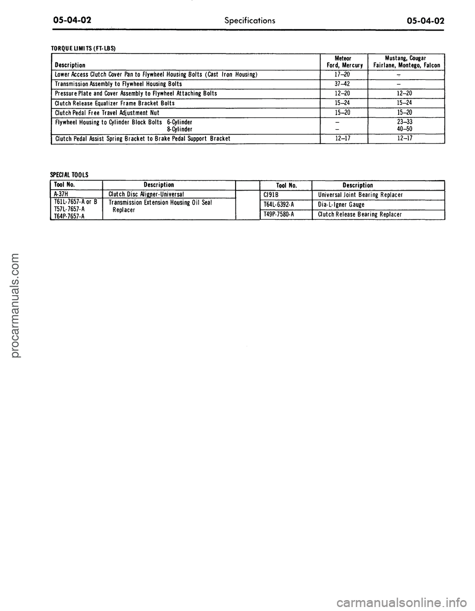
TORQUE LIMITS (FT-LBS)
Description
Lower Access Clutch Cover Pan to Flywheel Housing Bolts (Cast Iron Housing)
Transmission Assembly to Flywheel Housing Bolts
Pressure Plate and Cover Assembly to Flywheel Attaching Bolts
Clutch Release Equalizer Frame Bracket Bolts
Clutch Pedal Free Travel Adjustment Nut
Flywheel Housing to Cylinder Block Bolts
6-Cylinder
8-Cylinder
Clutch Pedal Assist Spring Bracket to Brake Pedal Support Bracket
Meteor
Ford,
Mercury
17-20
37-42
12-20
15-24
15-20
_
12-17
Mustang,
Cougar
Fairlane, Montego, Falcon
-
-
12-20
15-24
15-20
23-33
40-50
12-17
SPECIAL TOOLS
Tool No.
A-37H
T61L-7657-Aor B
T57L-7657-A
T64P-7657-A
Description
Clutch Disc Aligner-Universal
Transmission Extension Housing Oil Seal
Replacer
Tool No.
CJ91B
T64L-6392-A
T49P-7580-A
Description
Universal Joint Bearing Replacer
Dia-L-lgner Gauge
Clutch Release Bearing Replacerprocarmanuals.com
Page 278 of 413
06-02-09
Ford Design Three Speed Transmission
06-02-09
PRESS
RAM
OUTPUT SHAFT
SYNCHRONIZER
PRESS
RAM
OUTPUT SHAFT
Tool-T63P7025-A
SYNCHRONIZER
HUB
REMOVAL INSTALLATION c 1718-A
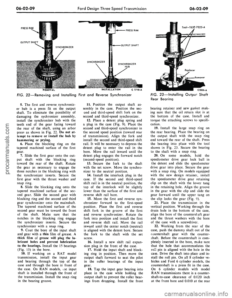
FIG. 22—Removing
and
Installing First
and
Reverse Synchronizer
5.
The
first
and
reverse synchroniz-
er
hub is a
press
fit on the
output
shaft.
To
eliminate
the
possibility
of
damaging
the
sychronizer assembly,
install
the
synchronizer
hub
with
the
teeth
end of the
gear facing toward
the rear
of the
shaft, using
an
arbor
press
as
shown
in Fig. 22. Do not at-
tempt
to
remove
or
install
the hub by
hammering
or
prying.
6. Place
the
blocking ring
on the
tapered machined surface
of the
first
gear.
7.
Slide
the
first gear onto
the out-
put shaft with
the
blocking ring
toward
the
rear
of the
shaft. Rotate
the gear
as
necessary
to
engage
the
three notches
in the
blocking ring with
the synchronizer inserts. Secure
the
first gear with
the
thrust washer
and
snap ring.
8. Slide
the
blocking ring onto
the
tapered machined surface
of the sec-
ond gear. Slide
the
second gear with
blocking ring
and the
second
and
third
gear synchronizer onto
the
mainshaft.
The tapered machined surface
of the
second gear must
be
toward
the
front
of
the
shaft. Make sure that
the
notches
in the
blocking ring engage
the synchronizer inserts. Secure
the
synchronizer with
a
snap ring.
9. Coat
the
bore
of the
input shaft
and gear with
a
thin film
of
grease.
A
thick film
of
grease will plug
the lu-
bricant holes
and
prevent lubrication
to
the
bearings. Install
the 15
bearings
(Fig.
15) in the
bore.
10.
If
working
on a RAT
model
transmission, install
the
input gear
and bearing through
the top of the
case
and
through
the
bore
in
front
of
the case.
On RAN
models,
me
input
shaft
is
installed through
the
front
of
the transmission. Install
the
snap ring
in
the
bearing groove.
11.
Position
the
output shaft
as-
sembly
in the
case. Position
the sec-
ond
and
third-speed shift fork
on the
second
and
third-speed synchronizer.
12.
Place
a
detent plug spring
and
a plug
in the
case
(Fig. 9).
Place
the
second
and
third-speed synchronizer
in
the second speed position (toward rear
of transmission). Align
the
fork
and
install
the
second
and
third-speed shift
rail.
It
will
be
necessary
to
depress
the
detent plug
to
enter
the
rail
in the
bore.
Move
the
rail inward until
the
detent plug engages
the
forward notch
(second-speed position).
13.
Secure
the
fork
to the
shaft
with
the set
screw. Move
the
synchro-
nizer
to the
neutral position.
14.
Install
the
interlock plug
in the
case.
If the
second
and
third-speed
shift rail
is in the
neutral position,
the
top
of the
interlock will
be
slightly
lower than
the
surface
of the
first
and
reverse shift rail bore.
15.
Move
the
first
and
reverse
syn-
chronizer forward
to the
first-speed
position. Place
the
first
and
reverse
shift fork
in the
groove
of the
first
and reverse synchronizer. Rotate
the
fork into position
and
install
the
first
and reverse shift rail. Move
the
rail
inward until
the
center notch (neutral)
is aligned with
the
detent bore. Secure
the fork
to the
shaft with
the set
screw.
16.
Install
a new
shift rail expan-
sion plug
in the
front
of the
case.
17.
Hold
the
input shaft
and
block-
ing ring
in
position. Then move
the
output shaft forward
to
seat
the
pilot
in
the
roller bearings
of the
input
gear.
18.
Tap the
input gear bearing into
place
in the
case while holding
the
output shaft
to
prevent
the
roller bear-
ings from dropping. Install
the
front
C1806-A
FIG. 23—Installing Output Shaft
Rear Bearing
bearing retainer
and new
gasket
mak-
ing sure that
the oil
return slot
is at
the bottom
of the
case. Install
and
torque
the
attaching screws
to
specifi-
cation.
19.
Install
the
large snap ring
on
the rear bearing. Place
the
bearing
on
the output shaft with
the
snap ring
end toward
the
rear
of the
shaft. Press
the bearing into place with
the
tool
shown
in Fig. 23.
Secure
the
bearing
to
the
shaft with
a
snap ring.
20.
On
some models, hold
the
speedometer drive gear lock ball
in
the detent
and
slide
the
speedometer
drive gear into place. Secure
the
gear
with
a
snap ring.
On
models equipped
with
the new
design retainer, install
the speedometer drive gear retaining
clip
on the
shaft with
the
lower tang
in
the
retaining hole. Align
the
groove
in
the
gear with
the
clip
and
slide
the
gear forward until
the
upper tang
on
the clip locks
the
gear
(Fig. 9).
21.
Place
the
transmission
in the
vertical position. Working through
the
drain hole
in the
bottom
of the
case,
align
the
bore
of the
countershaft gear
and
the
thrust washers with
the
bore
of
the
case with
a
screwdriver.
22.
Working from
the
rear
of the
case,
push
the
dummy shaft
out of the
countershaft gear with
the
counter-
shaft. Before
the
countershaft
is com-
pletely inserted
in the
bore, make sure
that
the
hole that accommodates
the
roll
pin is
aligned with
the
hole
in the
case.
Drive
the
shaft into place
and in-
stall
the
roll
pin. On all 8
cylinder
ve-
hicles
and
Ford
6
cylinder models,
the
countershaft
is a
press
fit in the
case.
On
6
cylinder models with model
RAN transmissions there
is a
counter-
shaft-to-case clearance
of
0.020 inch
at
the
front bore
and 0.010 at the
rearprocarmanuals.com
Page 279 of 413
06-02-10
Ford Design Three Speed Transmission
06-02-10
bore.
On these 6 cylinder models, in-
stall a new expansion plug in the
countershaft bore at the front of the
case.
23.
Coat a new extension housing
gasket with sealer and position it on
the case.
24.
Install lock washers on the five
attaching screws. Dip the threads of
the cap screws in sealer. Secure the
housing to the case and torque the
cap screws to specification.
25.
Install the filler and drain plugs
(if equipped) in the case. Make sure
that the magnetic plug is installed in
the bottom of the case.
7.6. Place the transmission in gear.
Pour lubricant over the entire gear
train while rotating the input or out-
put shaft.
27.
Install the remaining detent
plug in the case. Install the long
spring (which is retained by the case)
to secure the detent plug.
28.
Coat a new cover gasket (Fig.
5) with sealer. Secure the cover with
cap screws. Torque the screws to spec-
ification.
29.
Check the operation of the
transmission in all of the gear posi-
tions.procarmanuals.com
Page 282 of 413
06-03-03
Ford Design Four-Speed Transmission
06-03-03
cable from the equalizer lever and sep-
arate the lever from the crossmember.
5.
Remove the hairpin retainer se-
curing the cable to the transmission
rear support crossmember, and then
pull the cable assembly forward and
out of the crossmember.
6. Remove the retaining clip, flat
washer, and spring washer that se-
cures the shift rods to the shift levers.
7.
Remove the bolts that attach the
shift linkage control bracket to the ex-
tension housing and position the as-
sembly out of the way.
8. Support the engine with a trans-
mission jack and remove the extension
housing-to-engine rear support attach-
ing bolts.
9. Raise the rear of the engine high
enough to remove the weight from the
crossmember. Remove the bolts re-
taining the crossmember to the frame
side supports and remove the
crossmember.
10.
Support the transmission on a
jack and remove the bolts that attach
the transmission to the flywheel hous-
ing.
11.
Move the transmission and jack
rearward until the transmission input
shaft clears the flywheel housing. If
necessary, lower the engine enough to
obtain clearance for transmission re-
moval.
Do not depress the clutch pedal
while the transmission is removed.
INSTALLATION
1.
Make sure that the mounting
surface of the transmission and the
flywheel housing are free of dirt,
paint, and burrs. Install two guide
pins in the flywheel housing lower
mounting bolt holes. Move the trans-
mission forward on the guide pins
until the input shaft splines enter the
clutch hub splines and the case is posi-
tioned against the flywheel housing.
2.
Install the two upper transmis-
sion to flywheel housing, mounting
bolts snug, and then remove the two
guide pins. Install the two lower
mounting bolts. Torque all mounting
bolts to specifications.
3.
Raise the rear of the engine and
install the crossmember. Install and
torque the crossmember attaching
bolts to specifications, then lower the
engine.
4.
With the transmission extension
housing resting on the engine rear
support, install the transmission ex-
tension housing attaching bolts. Tor-
que the bolts to specifications.
5.
Position the shift linkage control
bracket to the extension housing and
install the attaching bolts.
6. Secure each shift rod to its re-
spective lever with the spring washer,
flat washer, and retaining pin.
7.
Guide the parking brake cable
assembly through the hole in the
transmission rear support crossmemb-
er. Secure the cable assembly to the
crossmember with the hair pin retain-
er.
8. Insert the parking brake front
cable in the equalizer and install the
equalizer in the bracket on the
crossmember. Secure the parking
brake rear cable to the equalizer.
9. Connect the speedometer cable
to the extension housing.
10.
Remove the extension housing
installation tool and slide the forward
end of the drive shaft over the trans-
mission output shaft. Connect the
drive shaft to the rear U-joint flange.
11.
Place both forward gear shift
levers and the reverse shift lever in the
neutral position and insert a 1/4 inch
diameter alignment tool in the shift
linkage alignment hole (Fig. 17). It
may be necessary to loosen the adjust-
ment nuts to install the alignment
tool. Adjust the linkage as necessary
and tighten the adjustment nuts to
specifications. Remove the alignment
tool.
12.
Fill the transmission to the
proper level with the specified lubri-
cant.
13.
Lower the car. Check tne shift
and crossover motion for full shift en-
gagement and smooth crossover oper-
ation.
MAJOR REPAIR OPERATIONS
DISASSEMBLY
1.
Mount the transmission in a
holding fixture and drain the lubri-
cant.
2.
Remove the cover attaching
screws from the case. Lift the cover
and gasket from the case.
3.
Remove the long spring that re-
tains the detent plug in the case (Fig.
4).
Remove the detent plug with a
small magnet.
4.
Remove the extension housing
attaching screws and lock washers.
Remove the housing and the gasket.
5.
Remove the input shaft bearing
retainer attaching screws. Slide the re-
tainer off the input shaft.
6. Support the countershaft gear
with a wire hook. Working from the
front of the case, push the counter-
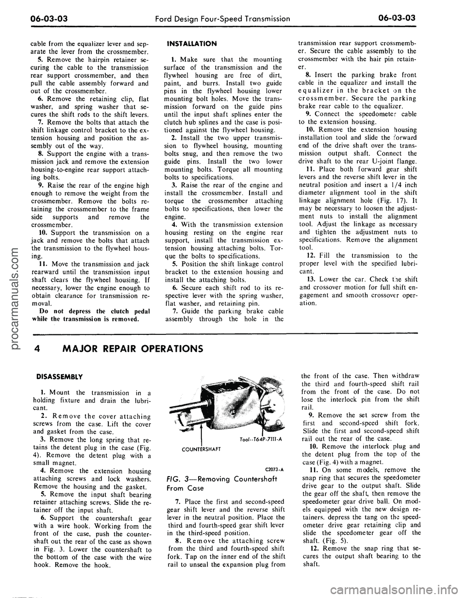
shaft out the rear of the case as shown
in Fig. 3. Lower the countershaft to
the bottom of the case with the wire
hook. Remove the hook.
Tool-T64P-711hA
COUNTERSHAFT
C2073-A
FIG. 3—Removing Countershaft
From Case
7.
Place the first and second-speed
gear shift lever and the reverse shift
lever in the neutral position. Place the
third and fourth-speed gear shift lever
in the third-speed position.
8. Remove the attaching screw
from the third and fourth-speed shift
fork. Tap on the inner end of the shift
rail to unseal the expansion plug from
the front of the case. Then withdraw
the third and fourth-speed shift rail
from the front of the case. Do not
lose the interlock pin from the shift
rail.
9. Remove the set screw from the
first and second-speed shift fork.
Slide the first and second-speed shift
rail out the rear of the case.
10.
Remove the interlock plug and
the detent plug from the top of the
case (Fig. 4) with a magnet.
11.
On some models, remove the
snap ring that secures the speedometer
drive gear to the output shaft. Slide
the gear off the shaft, then remove the
speedometer gear drive ball. On mod-
els equipped with the new design re-
tainers, depress the tang on the speed-
ometer drive gear retaining clip and
slide the speedometer gear off the
shaft. (Fig. 5).
12.
Remove the snap ring that se-
cures the output shaft bearing to the
shaft.procarmanuals.com
Page 284 of 413
06-03-05
Ford Design Four-Speed Transmission
06-03-05
DETAIL
4
FORD
AND
MERCURY
DETAIL
5
COUGAR. FAIRLANE,
FALCON,
MONTEGO,
AND MUSTANG
REVERSE SHIFT
RAIL
C1533-B
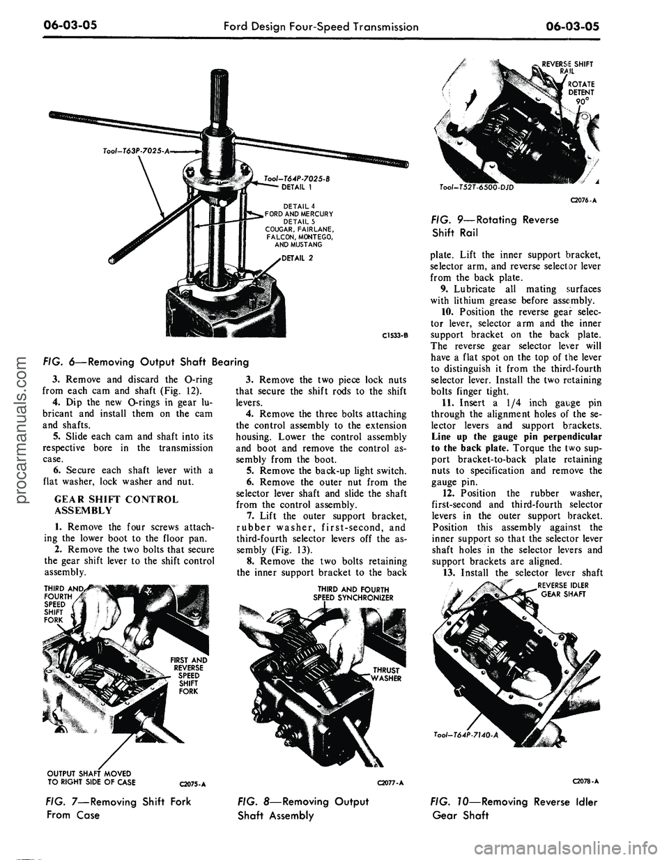
FIG. 6—Removing Output Shaft Bearing
3.
Remove
and
discard
the
O-ring
from each
cam and
shaft (Fig.
12).
4.
Dip the new
Orings
in
gear
lu-
bricant
and
install them
on the cam
and shafts.
5.
Slide each cam
and
shaft into
its
respective bore
in the
transmission
case.
6. Secure each shaft lever with
a
flat washer, lock washer
and nut.
GEAR SHIFT CONTROL
ASSEMBLY
1.
Remove
the
four screws attach-
ing
the
lower boot
to the
floor
pan.
2.
Remove the two bolts that secure
the gear shift lever
to
the shift control
assembly.
THIRD AND,
FOURTH
SPEED
SHIFT
FORK
FIRST
AND
REVERSE
SPEED
SHIFT
FORK
3.
Remove
the two
piece lock nuts
that secure
the
shift rods
to the
shift
levers.
4.
Remove
the
three bolts attaching
the control assembly
to the
extension
housing. Lower
the
control assembly
and boot
and
remove
the
control
as-
sembly from
the
boot.
5.
Remove the back-up light switch.
6. Remove
the
outer
nut
from
the
selector lever shaft
and
slide
the
shaft
from
the
control assembly.
7.
Lift
the
outer support bracket,
rubber washer, first-second,
and
third-fourth selector levers
off the as-
sembly (Fig.
13).
8. Remove
the two
bolts retaining
the inner support bracket
to the
back
THIRD
AND
FOURTH
SPEED SYNCHRONIZER
OUTPUT SHAFT MOVED
TO RIGHT SIDE
OF
CASE
C2075-A
C2077-A
Tool-T52T-
C2076-A
FIG. 9—Rotating Reverse
Shift Rail
plate. Lift
the
inner support bracket,
selector arm, and reverse selector lever
from
the
back plate.
9. Lubricate
all
mating surfaces
with lithium grease before assembly.
10.
Position
the
reverse gear selec-
tor lever, selector
arm and the
inner
support bracket
on the
back plate.
The reverse gear selector lever will
have
a
flat spot
on the
top
of
the lever
to distinguish
it
from
the
third-fourth
selector lever. Install the two retaining
bolts finger tight.
11.
Insert
a 1/4
inch gauge
pin
through
the
alignment holes
of the se-
lector levers
and
support brackets.
Line
up the
gauge
pin
perpendicular
to the back plate. Torque the two sup-
port bracket-to-back plate retaining
nuts
to
specification
and
remove
the
gauge
pin.
12.
Position
the
rubber washer,
first-second
and
third-fourth selector
levers
in the
outer support bracket.
Position this assembly against
the
inner support
so
that the selector lever
shaft holes
in the
selector levers
and
support brackets
are
aligned.
13.
Install
the
selector lever shaft
"~ REVERSE IDLER
GEAR SHAFT
Tool-T64P-7140
C2078-A
FIG. 7—Removing Shift Fork
From Case
FIG. 8—Removing Output
Shaft Assembly
FIG. TO—Removing Reverse Idler
Gear Shaftprocarmanuals.com
Page 285 of 413
06-03-06
Ford Design Four-Speed Transmission
06-03-06
BEARING
7C
SPEEDOMETER
DRIVE GEAR
172
OUTPUT
SHAFT
SEAL
SNAP RING 7Aon
SPEEDOMETER GEAR
DRIVE BALL
353351•S
BLOCKING RING
7107
FIRST AND SECOND
SPEED SYNCHRONIZER
7124
SECOND SPEED GEAR
7102
THIRD AND FOURTH
SPEED SYNCHRONIZER
•7124
SNAP RING - 7109
FIG.
7
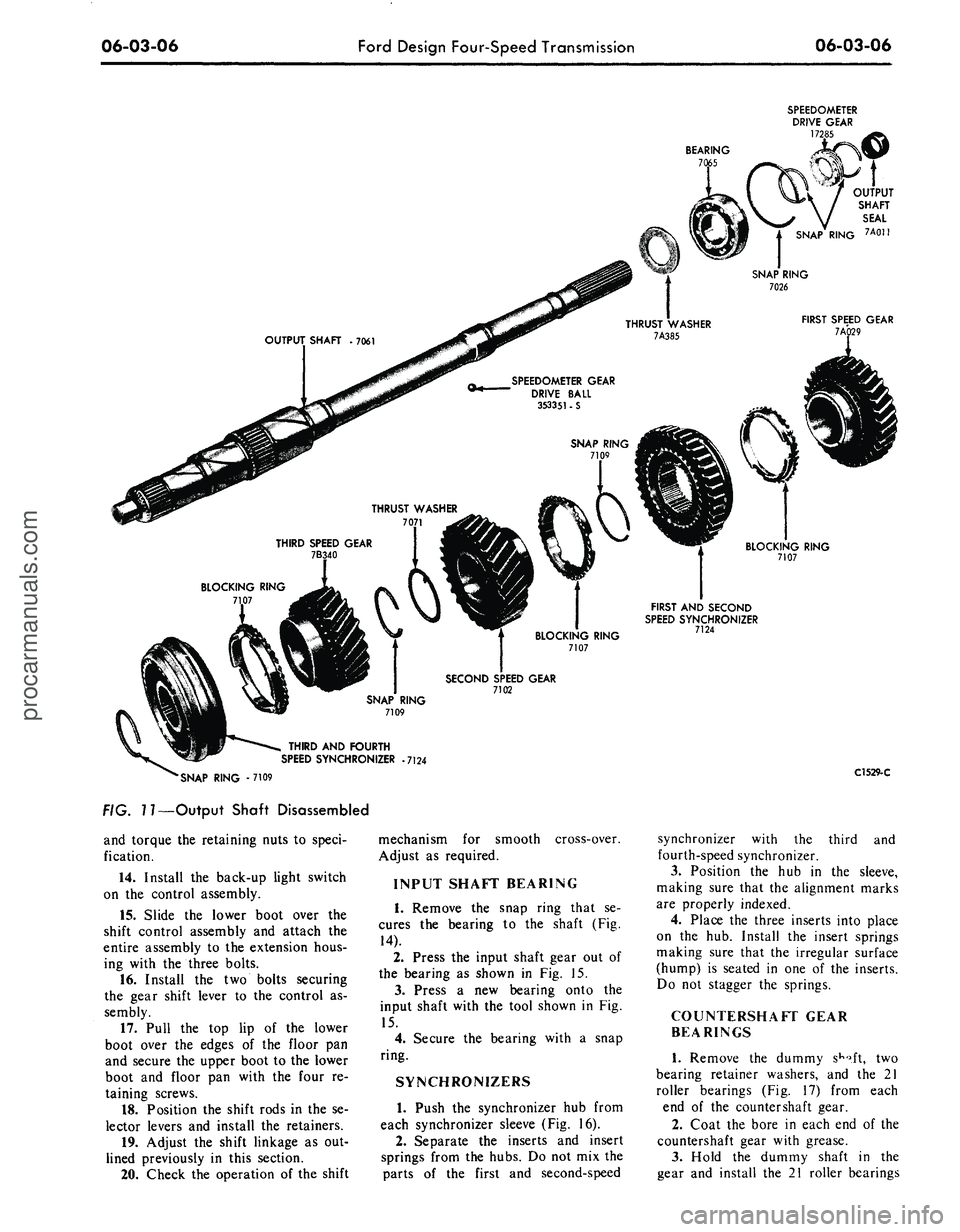
7—Output Shaft Disassembled
and torque the retaining nuts to speci-
fication.
14.
Install the back-up light switch
on the control assembly.
15.
Slide the lower boot over the
shift control assembly and attach the
entire assembly to the extension hous-
ing with the three bolts.
16.
Install the two bolts securing
the gear shift lever to the control as-
sembly.
17.
Pull the top lip of the lower
boot over the edges of the floor pan
and secure the upper boot to the lower
boot and floor pan with the four re-
taining screws.
18.
Position the shift rods in the se-
lector levers and install the retainers.
19.
Adjust the shift linkage as out-
lined previously in this section.
20.
Check the operation of the shift
mechanism for smooth
Adjust as required.
cross-over.
INPUT SHAFT BEARING
1.
Remove the snap ring that se-
cures the bearing to the shaft (Fig.
14).
2.
Press the input shaft gear out of
the bearing as shown in Fig. 15.
3.
Press a new bearing onto the
input shaft with the tool shown in Fig.
15.
4.
Secure the bearing with a snap
ring.
SYNCHRONIZERS
1.
Push the synchronizer hub from
each synchronizer sleeve (Fig. 16).
2.
Separate the inserts and insert
springs from the hubs. Do not mix the
parts of the first and second-speed
C1529-C
synchronizer with the third and
fourth-speed synchronizer.
3.
Position the hub in the sleeve,
making sure that the alignment marks
are properly indexed.
4.
Place the three inserts into place
on the hub. Install the insert springs
making sure that the irregular surface
(hump) is seated in one of the inserts.
Do not stagger the springs.
COUNTERSHAFT GEAR
BEARINGS
1.
Remove the dummy
sKo.ft,
two
bearing retainer washers, and the 21
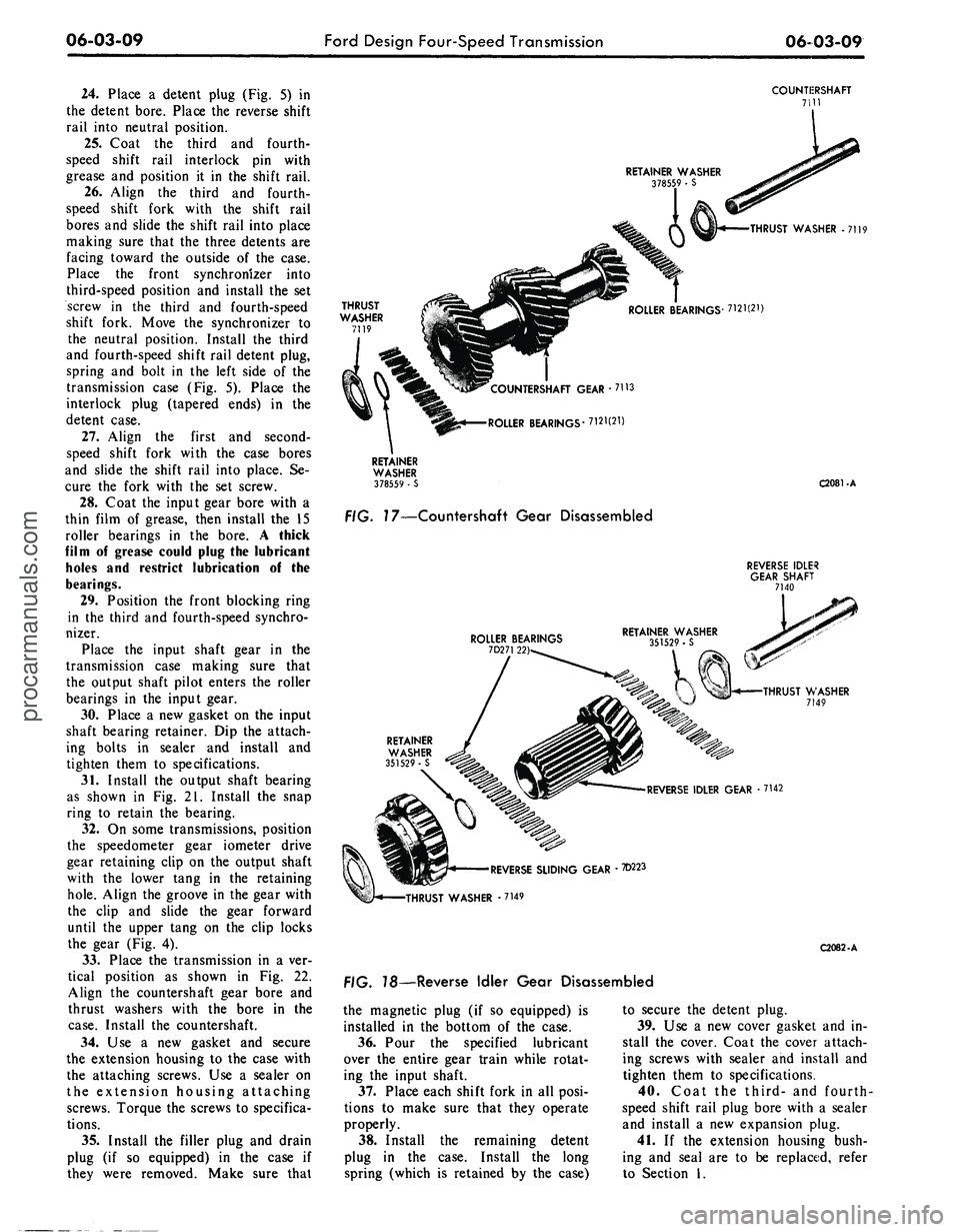
roller bearings (Fig. 17) from each
end of the countershaft gear.
2.
Coat the bore in each end of the
countershaft gear with grease.
3.
Hold the dummy shaft in the
gear and install the 21 roller bearingsprocarmanuals.com
Page 288 of 413
06-03-09
Ford Design Four-Speed Transmission
06-03-09
24.
Place a detent plug (Fig. 5) in
the detent bore. Place the reverse shift
rail into neutral position.
25.
Coat the third and fourth-
speed shift rail interlock pin with
grease and position it in the shift rail.
26.
Align the third and fourth-
speed shift fork with the shift rail
bores and slide the shift rail into place
making sure that the three detents are
facing toward the outside of the case.
Place the front synchronizer into
third-speed position and install the set
screw in the third and fourth-speed
shift fork. Move the synchronizer to
the neutral position. Install the third
and fourth-speed shift rail detent plug,
spring and bolt in the left side of the
transmission case (Fig. 5). Place the
interlock plug (tapered ends) in the
detent case.
27.
Align the first and second-
speed shift fork with the case bores
and slide the shift rail into place. Se-
cure the fork with the set screw.
28.
Coat the input gear bore with a
thin film of grease, then install the 15
roller bearings in the bore. A thick
film of grease could plug the lubricant
holes and restrict lubrication of the
bearings.
29.
Position the front blocking ring
in the third and fourth-speed synchro-
nizer.
Place the input shaft gear in the
transmission case making sure that
the output shaft pilot enters the roller
bearings in the input gear.
30.
Place a new gasket on the input
shaft bearing retainer. Dip the attach-
ing bolts in sealer and install and
tighten them to specifications.
31.
Install the output shaft bearing
as shown in Fig. 21. Install the snap
ring to retain the bearing.
32.
On some transmissions, position
the speedometer gear iometer drive
gear retaining clip on the output shaft
with the lower tang in the retaining
hole.
Align the groove in the gear with
the clip and slide the gear forward
until the upper tang on the clip locks
the gear (Fig. 4).
33.
Place the transmission in a ver-
tical position as shown in Fig. 22.
Align the countershaft gear bore and
thrust washers with the bore in the
case.
Install the countershaft.
34.
Use a new gasket and secure
the extension housing to the case with
the attaching screws. Use a sealer on
the extension housing attaching
screws. Torque the screws to specifica-
tions.
35.
Install the filler plug and drain
plug (if so equipped) in the case if
they were removed. Make sure that
COUNTIERSHAFT
7111
RETAINER WASHER
378559 • S
THRUST WASHER -7119
THRUST
WASHER
7119
ROLLER BEARINGS- 7121(21)
COUNTERSHAFT GEAR - 7113
ROLLER BEARINGS'7121(21)
RETAINER
WASHER
378559 • S
FIG. 17—Countershaft Gear Disassembled
C2081-A
REVERSE IDLER
GEAR SHAFT
7140
ROLLER BEARINGS
7D271 22)
THRUST WASHER
7149
RETAINER
WASHER
351529 - S
REVERSE IDLER GEAR -7142
'REVERSE SLIDING GEAR • 7D223
•THRUST WASHER • 7149
FIG. 78—Reverse Idler Gear Disassembled
C2082-A
the magnetic plug (if so equipped) is
installed in the bottom of the case.
36.
Pour the specified lubricant
over the entire gear train while rotat-
ing the input shaft.
37.
Place each shift fork in all posi-
tions to make sure that they operate
properly.
38.
Install the remaining detent
plug in the case. Install the long
spring (which is retained by the case)
to secure the detent plug.
39.
Use a new cover gasket and in-
stall the cover. Coat the cover attach-
ing screws with sealer and install and
tighten them to specifications.
40.
Coat the third- and fourth-
speed shift rail plug bore with a sealer
and install a new expansion plug.
41.
If the extension housing bush-
ing and seal are to be replaced, refer
to Section 1.procarmanuals.com
Page 291 of 413
06-04-02
Specifications
06-04-02
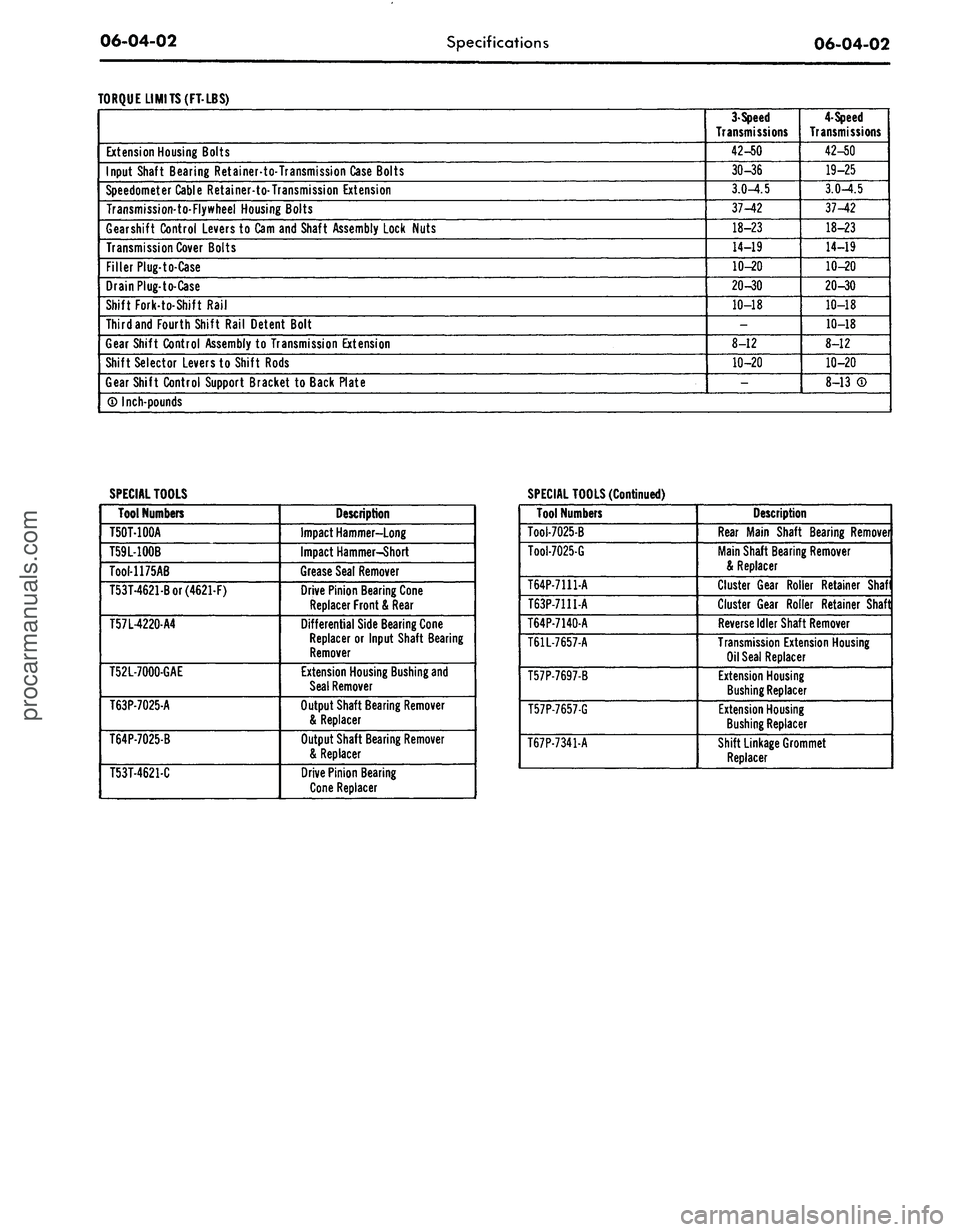
TORQUE LIMITS(FT-LBS)
Extension Housing Bolts
Input Shaft Bearing Retainer-to-Transmission Case Bolts
Speedometer Cable Retainer-to-Transmission Extension
Transmission-to-Flywheel Housing Bolts
Gearshift Control Levers to Cam and Shaft Assembly Lock Nuts
Transmission Cover Bolts
Filler Plug-to-Case
Drain Plug-to-Case
Shift Fork-to-Shift Rail
Third and Fourth Shift Rail Detent Bolt
Gear Shift Control Assembly
to
Transmission Extension
Shift Selector Levers to Shift Rods
Gear Shift Control Support Bracket
to
Back Plate
3-Speed
Transmissions
42-50
30-36
3.0-4.5
37-42
18-23
14-19
10-20
20-30
10-18
-
8-12
10-20
-
4-Speed
Transmissions
42-50
19-25
3.0-4.5
37-42
18-23
14-19
10-20
20-30
10-18
10-18
8-12
10-20
8-13
® Inch-pounds
SPECIAL TOOLS
SPECIAL TOOLS (Continued)
Tool Numbers
T50T-100A
T59L-100B
Tool-1175AB
T53T-4621-Bor(4621-F)
T57L-4220-A4
T52L-7000-GAE
T63P-7025-A
T64P-7025-B
T53T-4621-C
Description
Impact Hammer-Long
Impact Hammer-Short
Grease Seal Remover
Drive Pinion Bearing Cone
Replacer Front
&
Rear
Differential Side Bearing Cone
Replacer
or
Input Shaft Bearing
Remover
Extension Housing Bushing and
Seal Remover
Output Shaft Bearing Remover
& Replacer
Output Shaft Bearing Remover
& Replacer
Drive Pinion Bearing
Cone Replacer
Tool Numbers
Tool-7025-B
Tool-7025-G
T64P-7111-A
T63P-7111-A
T64P-7140-A
T61L-7657-A
T57P-7697-B
T57P-7657-G
T67P-7341-A
Description
Rear Main Shaft Bearing Removei
Main Shaft Bearing Remover
& Replacer
Cluster Gear Roller Retainer Shaf
Cluster Gear Roller Retainer Shaft
Reverse Idler Shaft Remover
Transmission Extension Housing
Oil Seal Replacer
Extension Housing
Bushing Replacer
Extension Housing
Bushing Replacer
Shift Linkage Grommet
Replacerprocarmanuals.com
Page 295 of 413
07-01-04
General Transmission Service
07-01-04
taching bolts to the proper torque. If
necessary, replace the gasket.
Check the fluid filler tube connec-
tion at the transmission case or pan.
If leakage is found here, install a new
O-ring or tighten the fitting to the
specified torque.
Check the fluid lines and fittings
between the transmission and the
cooler in the radiator tank for loose-
ness,
wear, or damage. If leakage can-
not be stopped by tightening a fitting,
replace the damaged parts.
Check the engine coolant in the ra-
diator. If transmission fluid is present
in the coolant, the cooler in the radia-
tor is probably leaking.
The cooler can be further checked
for leaks by disconnecting the lines
from the cooler fittings and applying
50-75 psi air pressure to the fittings.
Remove the radiator cap to relieve the
pressure build at the exterior of the oil
cooler tank. If the cooler is leaking
and will not hold this pressure the
cooler must be replaced. Cooler re-
placement is described in the Cooling
System Section of Group 11.
If leakage is found at either the
downshift control lever shaft or the
manual lever shaft, replace either or
both seals.
Inspect the pipe plug on the left
side of the transmission case at the
front. If the plug shows leakage, tor-
que the plug to specifications. If tight-
ening does not stop the leaks, replace
the plug. On a C6 transmission, a TV
pressure plug is also provided on the
right rear side of the case.
When converter drain plugs leak,
remove drain plugs with a six-point
wrench. Coat the threads with FoMo-
Co Perfect Seal Sealing Compound or
its equivalent, and install the plugs.
Torque the drain plugs to specifica-
tion. Fluid leakage from the converter
housing may be caused by engine oil
leaking past the rear main bearing or
from oil gallery plugs, or power steer-
ing oil leakage from steering system.
Be sure to determine the exact cause
of the leak before repair procedures
are started.
Oil-soluble aniline or fluorescent dyes
premixed at the rate of 1/2 teaspoon
of dye powder to 1/2 pint of transmis-
sion fluid have proved helpful in locat-
ing the source of the fluid leakage.
Such dyes may be used to determine
whether an engine oil or transmission
fluid leak is present or if the fluid in
the oil cooler leaks into the engine
coolant system. A black light, how-
ever, must be used with the fluorescent
dye solution.
DISHED OR
FLAT WASHER
" O.D.,
a" STEEL PLATE
5/8"X \W,
DRILL TO SUIT
HEX. HEAD SCREW
3/8"-24 X Vl
HEX. NUT W—
24
WELD
TOGETHER
WING
NUT
>/2"_13
THREAD
CHAIN,
10"
LONG
RUBBER PLUG
1
Vi" DIA. X 2"
LONG Vl"
HOLE THRU
APPROXIMATELY
40 DUROMETER
FLAT WASHER
Vs" O.D.
PLUG
VALVE
STANDARD BOLT
W-13
X 4Vl"
LONG SQUARE
THREAD
END
REMOVE HEAD
AND WELD
TO
WASHER
STANDARD 1/8" FITTING-87971-S FOR
RETAPPED DRAIN PLUG THREADS-USE
1/4" OVERSIZE FITTING-87973-S
D 1067-B
WELD TOGETHER
SECURELY—MUST
NOT LEAK
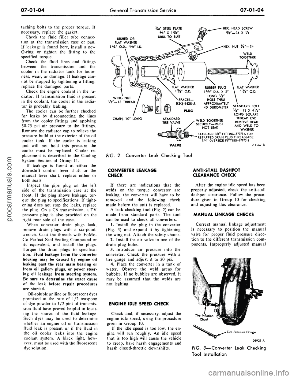
FIG. 2—Converter Leak Checking Tool
CONVERTER LEAKAGE
CHECK
If there are indications that the
welds on the torque converter are
leaking, the converter will have to be
removed and the following check
made before the unit is replaced.
A leak checking tool (Fig. 2) can be
made from standard parts. The tool
can be used to check all converters.
1.
Install the plug in the converter
(Fig. 3) and expand it by tightening
the wing nut. Attach the safety chains.
2.
Install the air valve in one of the
drain plug holes.
3.
Introduce air pressure into the
converter. Check the pressure with a
tire gauge and adjust it to 20 psi.
4.
Place the converter in a tank of
water. Observe the weld areas for
bubbles. If no bubbles are observed, it
may be assumed that the welds are
not leaking.
ENGINE IDLE SPEED CHECK
Check and, if necessary, adjust the
engine idle speed, using the procedure
given in Group 10.
If the idle speed is too low, the en-
gine will run roughly. An idle speed
that is too high will cause the vehicle
to creep, have harsh engagements and
harsh closed-throttle downshifts.
ANTI-STALL DASHPOT
CLEARANCE CHECK
After the engine idle speed has been
properly adjusted, check the anti-stall
dashpot clearance. Follow the proce-
dure given in Group 10 for checking
and adjusting this clearance.
MANUAL LINKAGE CHECKS
Correct manual linkage adjustment
is necessary to position the manual
valve for proper fluid pressure direc-
tion to the different transmission com-
ponents. Improperly adjusted manual
Tire Pressure Gauge
D1921-A
FIG. 3—Converter Leak Checking
Tool Installationprocarmanuals.com
Page 300 of 413
07-01-09
General Transmission Service
07-01-09
For example, on a C4 transmission,
if the pressure at 10 inches of vacuum
was 120 psi and the pressure at 1.0
inch of vacuum was 170 psi, and up-
shifts and downshifts were harsh, a di-
aphragm adjustment to reduce the di-
aphragm assembly spring force would
be required.
If the pressure readings are low, an
adjustment to increase diaphragm
spring force is required.
To increase control pressure, turn
the adjusting screw in clockwise to re-
duce control pressure, back the adjust-
ing screw out by turning it counte-
rclockwise. One complete turn of the
adjusting screw (360 degrees) will
change idle line control pressure ap-
proximately 2-3 psi. After the adjust-
ment is made, install the vacuum line
and make all the pressure checks as
outlined in the Specification Section.
The diaphragm should not be ad-
justed to provide pressure below the
ranges shown in the Specification Sec-
tion in order to change shift feel. To
do so could result in soft or slipping
shift points and damage to the trans-
mission.
ALTITUDE
COMPENSATING TYPE
The altitude—compensating di-
aphragm is provided with an adjust-
ment screw located in the vacuum
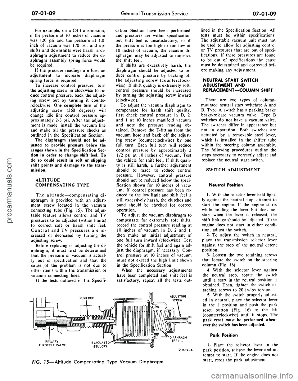
connecting tube (Fig. 15). The adjus-
table feature allows control and TV
pressures to be adjusted (within limits)
to correct soft or harsh shift feel.
Control and TV pressures are in-
creased or decreased by turning the
adjusting screw.
Before replacing or adjusting the di-
aphragm, it must first be determined
that the pressure or vacuum is actual-
ly out of specification and that the
cause of the problem is not due to
other items within the transmission or
vacuum connecting lines.
If the tests outlined in the Specifi-
cation Section have been performed
and pressures are within specification
but shift feel is unsatisfactory, or if
the pressure is too high or too low at
10 inches of vacuum, the vacuum di-
aphragm may be adjusted to improve
the shift feel.
If shifts are excessively harsh, the
diaphragm should be adjusted to re-
duce control pressure by backing off
the adjusting screw (counterclock-
wise).
If shift quality is extremely soft,
control pressure should be increased
by turning the adjusting screw inward
(clockwise).
To adjust the vacuum diaphragm to
compensate for harsh shift quality,
first check control pressure in D, 2
and 1 at 10 inches manifold vacuum
and note the pressure reading ob-
tained. Remove the T-fitting from the
vacuum hose and back off the adjust-
ing screw (counterclockwise) by one
full turn. Each full turn will reduce
control pressure by approximately 2
1/2 psi at 10 inches of vacuum. Test
the vehicle for shift feel. If shift quali-
ty is still harsh, a further adjustment
should be made to reduce control
pressure. However, control pressure
should not be reduced below the speci-
fication shown for 10 inches of vacu-
um. If control pressure has been re-
duced to the low limit and shift feel is
still excessively harsh, the clutches and
band should be checked for correct
operation.
To adjust the vacuum diaphragm to
compensate for extremely soft shifts,
record the control pressure reading at
10 inches of vacuum in D, 2 and 1,
then make an initial adjustment of
one full turn inward (clockwise). Test
the vehicle for shift feel and again ad-
just the diaphragm, if necessary. Con-
trol pressure at 10 inches of vacuum
must not exceed the high limit shown
in the Specification Section.
When the necessary adjustments
have been completed and shift feel is
satisfactory, repeat all the tests out-
ADJUSTING
SCREW
PRIMARY
THROTTLE VALVE
DIAPHRAGM
SPRING
D 1639-A
FIG. 15—Altitude Compensating Type Vacuum Diaphragm
lined in the Specification Section. All
tests must be within specifications.
The adjustable vacuum unit must not
be used to allow for adjusting control
or TV pressures that are out of speci-
fications. If these pressures are found
to be out of specifications the cause
must be determined and corrected bef-
ore making any adjustment.
NEUTRAL START SWITCH
ADJUSTMENT AND
REPLACEMENT—COLUMN SHIFT
There are two types of column-
mounted neutral start switches: A and
B.
Type A switch has a parking brake
brake-release vacuum valve. Type B
switches do not have a vacuum valve.
The switches differ in appearance but
not in operation. Both switches are
actuated by a removable steel lever,
which is installed in the shifter tube
within the steering column assembly.
The following procedures outline the
steps necessary to correctly adjust and
replace the neutral start switch.
SWITCH ADJUSTMENT
Neutral Position
1.
With the selector lever held light-
ly against the neutral stop, attempt to
start the engine. If the engine starts
while holding the lever but does not
start when the lever is released, the
shift linkage should be adjusted. If the
engine does not start in either condi-
tion, adjust the switch.
2.
To adjust the switch in neutral,
place the transmission selector lever
against the stop of the neutral detent
position.
3.
Loosen the two retaining screws
that locate the switch on the steering
column (Fig. 16).
4.
With the selector lever against
the neutral stop, rotate the switch
until a start in the neutral position is
obtained. Then, tighten the switch at-
taching screws to 20 in-lbs torque.
5.
With the switch properly adjust-
ed in neutral, place the selector lever
in the 1 position and push the park
reset button (Fig. 16) to the left
(counterclockwise) until it stops. The
park reset must be performed when-
ever the switch has been adjusted.
Park Position
1.
Place the selector lever in the
park position, release the lever and at-
tempt to start. If the engine does not
start, reset the park adjustment.procarmanuals.com