torque FORD MUSTANG 1969 Volume One Chassis
[x] Cancel search | Manufacturer: FORD, Model Year: 1969, Model line: MUSTANG, Model: FORD MUSTANG 1969Pages: 413, PDF Size: 75.81 MB
Page 301 of 413
07-01-10
General Transmission Service
07-01-10
2.
To adjust the switch for the park
position, place the transmission selec-
tor lever in 1 and push the park reset
button (Fig. 16) to the left (counter-
clockwise) until it stops.
3.
Check the operation of the
switch in each selector lever position.
The starter should engage in only the
neutral and park positions. Be sure to
perform
the
park reset
if for any rea-
son
the
neutral switch
is
adjusted.
If,
after performing
the
switch
ad-
justments,
the
starter still will
not en-
gage
in the
neutral
or
park positions,
replace
the
switch. Never replace
the
neutral switch until
the
switch adjust-
ments have been made.
SWITCH REPLACEMENT
1.
Disconnect the neutral start
switch wires at the plug connector.
2.
Disconnect the vacuum hoses, if
so equipped.
3.
Remove the two screws securing
the neutral start switch to the steering
column and lift the switch from the
column.
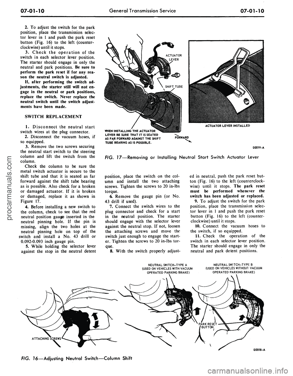
Check the column to be sure the
metal switch actuator is secure to the
shift tube and that it is seated as far
forward against the shift tube bearing
as is possible. Also check for a broken
or damaged actuator. If it is broken
or damaged, replace it as shown in
Figure 17.
4.
Before installing a new switch to
the column, check to see that the red
neutral position gauge inserted in the
neutral pinning hole. If the pin is
missing, align the two holes at the
neutral pinning hole on top of the
switch and install a No. 43 drill or
0.092-0.093 inch gauge pin.
5.
While holding the selector lever
against the stop in the neutral detent
ACTUATOR LEVER INSTALLED
WHEN INSTALLING
THE
ACTUATOR
LEVER
BE
SURE THAT
IT
1$ SEATED
AS
FAR
FORWARD AGAINST
THE
SHIFT
TUBE BEARING
AS IS
POSSIBLE.
FORWARD
D2019-A
FIG. 17—Removing
or
Installing Neutral Start Switch Actuator Lever
position, place the switch on the col-
umn and install the two attaching
screws. Tighten the screws to 20 in-lbs
torque.
6. Remove the gauge pin (or No.
43 drill if used).
7.
Connect the switch wires to the
plug connector and check for a start
in the neutral position. The starter
should engage with the selector lever
against the neutral stop. If not, loosen
the attaching screws and move the
switch just enough to engage the start-
er. Tighten the screws to 20 in-lbs tor-
que.
8. With the switch properly adjust-
ed in neutral, push the park reset but-
ton (Fig. 16) to the left (counterclock-
wise) until it stops. The park reset
must be performed whenever the
switch has been adjusted or replaced.
9. To adjust the switch for the park
position, place the transmission selec-
tor lever in 1 and push the park reset
button (Fig. 16) to the left (counter-
clockwise) until it stops.
10.
Connect the vacuum hoses to
the switch, if so equipped.
11.
Check the operation of the
switch in each selector lever position.
The starter should engage in only the
neutral and park detent positions.
NEUTRAL SWITCH-TYPE
A
(USED
ON
VEHICLES WITH VACUUM
OPFRATED PARKING BRAKE)
NEUTRAL SWITCH-TYPIE
B
(USED
ON
VEHICLES WITHOUT VACUUM
OPERATED PARKING BRAKE)
ATTACHING
FIG.
16—Ad
justing Neutral Switch—Column Shift
D2018-Aprocarmanuals.com
Page 302 of 413
07-01-11
General Transmission Service
07-01-11
STOP
PIN
GROMMET
Tool - T67P-734LA
GROMMET
LEVER
CONTROL ROD REMOVAL
GROMMET INSTALLATION
Tool - T67P-734LA
r
CONTROL ROD INSTALLATION
3/16"-1/4'
CONTROL ROD
STOP
PIN
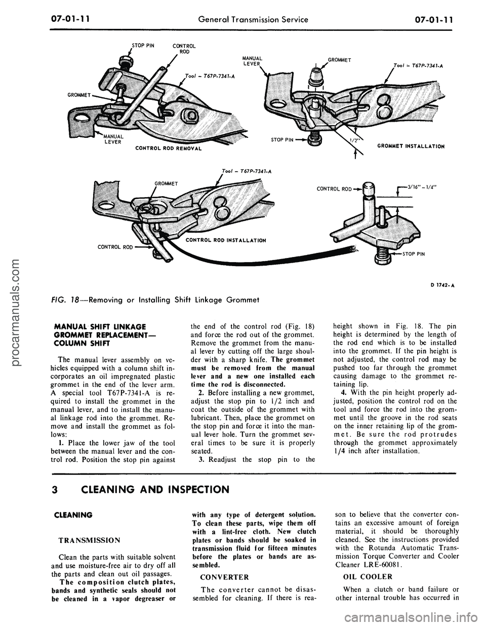
FIG. 18—Removing
or
Installing Shift Linkage Grommet
D 1742-A
MANUAL SHIFT LINKAGE
GROMMET REPLACEMENT-
COLUMN SHIFT
The manual lever assembly
on ve-
hicles equipped with
a
column shift
in-
corporates
an oil
impregnated plastic
grommet
in the end of the
lever
arm.
A special tool T67P-7341-A
is re-
quired
to
install
the
grommet
in the
manual lever,
and to
install
the
manu-
al linkage
rod
into
the
grommet.
Re-
move
and
install
the
grommet
as fol-
lows:
1.
Place
the
lower
jaw of the
tool
between
the
manual lever
and the con-
trol
rod.
Position
the
stop
pin
against
the
end of the
control
rod (Fig. 18)
and force
the rod out of the
grommet.
Remove
the
grommet from
the
manu-
al lever
by
cutting
off the
large shoul-
der with
a
sharp knife.
The
grommet
must
be
removed from
the
manual
lever
and a new one
installed each
time
the rod is
disconnected.
2.
Before installing
a
new grommet,
adjust
the
stop
pin to 1/2
inch
and
coat
the
outside
of the
grommet with
lubricant. Then, place
the
grommet
on
the stop
pin and
force
it
into
the
man-
ual lever hole. Turn
the
grommet
sev-
eral times
to be
sure
it is
properly
seated.
3.
Readjust
the
stop
pin to the
height shown
in Fig. 18. The pin
height
is
determined
by the
length
of
the
rod end
which
is to be
installed
into
the
grommet.
If the pin
height
is
not adjusted,
the
control
rod may be
pushed
too far
through
the
grommet
causing damage
to the
grommet
re-
taining
lip.
4.
With
the pin
height properly
ad-
justed, position
the
control
rod on the
tool
and
force
the rod
into
the
grom-
met until
the
groove
in the rod
seats
on
the
inner retaining
lip of the
grom-
met.
Be
sure
the rod
protrudes
through
the
grommet approximately
1/4 inch after installation.
CLEANING
AND
INSPECTION
CLEANING
TRANSMISSION
Clean
the
parts with suitable solvent
and
use
moisture-free
air to dry off all
the parts
and
clean
out oil
passages.
The composition clutch plates,
bands
and
synthetic seals should
not
be cleaned
in a
vapor degreaser
or
with
any
type
of
detergent solution.
To clean these parts, wipe them
off
with
a
lint-free cloth.
New
clutch
plates
or
bands should
be
soaked
in
transmission fluid
for
fifteen minutes
before
the
plates
or
bands
are as-
sembled.
CONVERTER
The converter cannot
be
disas-
sembled
for
cleaning.
If
there
is rea-
son
to
believe that
the
converter
con-
tains
an
excessive amount
of
foreign
material,
it
should
be
thoroughly
cleaned.
See the
instructions provided
with
the
Rotunda Automatic Trans-
mission Torque Converter
and
Cooler
Cleaner LRE-60081.
OIL COOLER
When
a
clutch
or
band failure
or
other internal trouble
has
occurred
inprocarmanuals.com
Page 303 of 413
07-01-12
General Transmission Service
07-01-12
the transmission,
any
metal particles
or clutch plate
or
band material that
may have been carried into
the
cooler
should
be
removed from
the
system
by
flushing
the
cooler
and
lines before
the transmission
is put
back into serv-
ice.
In no
case should
an
automatic
transmission having
a
clutch
or
band
failure
or
other internal trouble result-
ing
in
fluid contamination,
be put
back into service without first flushing
the transmission
oil
cooler.
To flush
the oil
cooler, follow
the
instruct!
on >
provided with
the
Rotun-
da Automatic Transmission Torque
Converter
and
Cooler Cleaner
LRE-
60081.
INSPECTION
TURBINE
AND
STATOR
END
PLAY CHECK
A special tool
(Fig. 19)
must
be
used
to
check
the
condition
of the
converter. This special tool
is
used
to
check
the
turbine
and
stator
end
play
and
the
operation
of the
one-way
sta-
tor clutch.
CRUISE-O-MATIC
Too/-T58L-7902-A
C-4 AND C-6 TRANSMISSION
Tool-T59P.7902.Bor 7937-B
ON C-4 AND C-6 TRANSMISSION
Tool-T64L-7902-A
D
1499-E
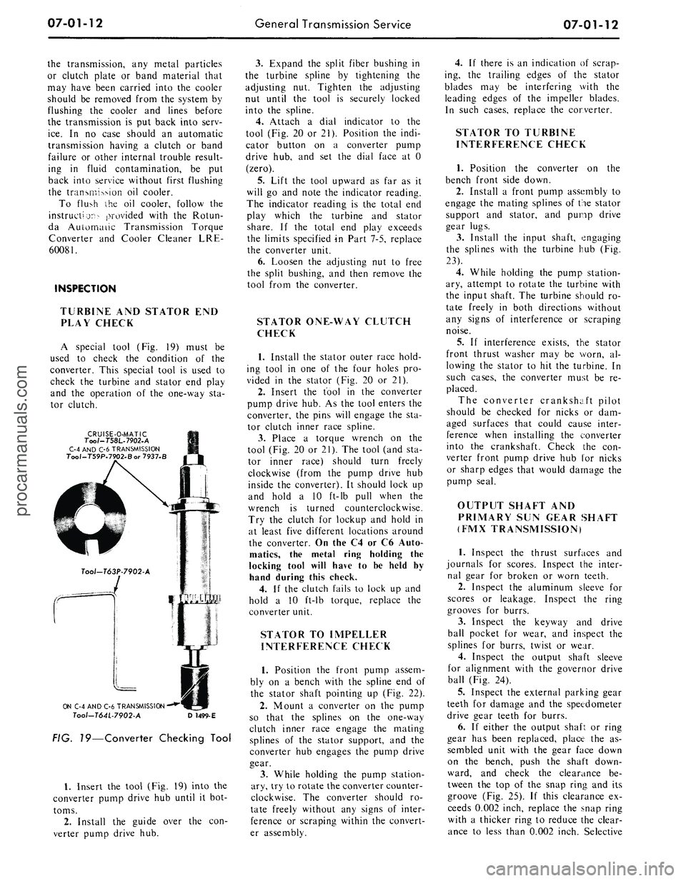
FIG. 19—Converter Checking Tool
1.
Insert
the
tool (Fig.
19)
into
the
converter pump drive
hub
until
it
bot-
toms.
2.
Install
the
guide over
the con-
verter pump drive
hub.
3.
Expand
the
split fiber bushing
in
the turbine spline
by
tightening
the
adjusting
nut.
Tighten
the
adjusting
nut until
the
tool
is
securely locked
into
the
spline.
4.
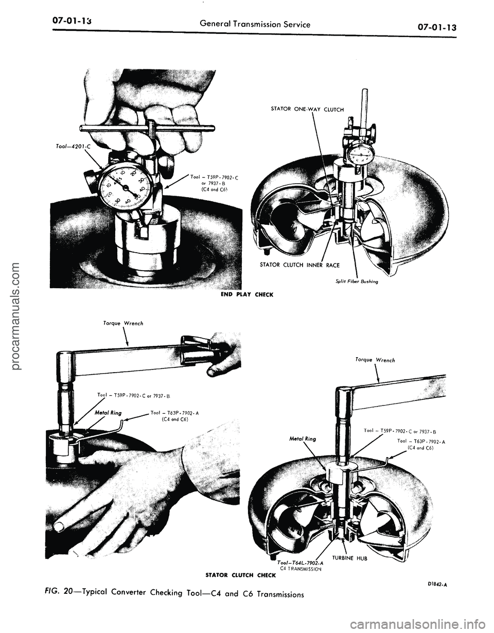
Attach
a
dial indicator
to the
tool (Fig.
20 or
21). Position
the
indi-
cator button
on a
converter pump
drive
hub, and set the
dial face
at 0
(zero).
5.
Lift
the
tool upward
as far as it
will
go and
note
the
indicator reading.
The indicator reading
is the
total
end
play which
the
turbine
and
stator
share.
If the
total
end
play exceeds
the limits specified
in
Part 7-5, replace
the converter unit.
6. Loosen
the
adjusting
nut to
free
the split bushing,
and
then remove
the
tool from
the
converter.
STATOR ONE-WAY CLUTCH
CHECK
1.
Install
the
stator outer race hold-
ing tool
in one of the
four holes
pro-
vided
in the
stator (Fig.
20 or 21).
2.
Insert
the
tool
in the
converter
pump drive hub.
As the
tool enters
the
converter,
the
pins will engage
the sta-
tor clutch inner race spline.
3.
Place
a
torque wrench
on the
tool (Fig.
20 or
21).
The
tool (and
sta-
tor inner race) should turn freely
clockwise (from
the
pump drive
hub
inside
the
converter).
It
should lock
up
and hold
a 10
ft-lb pull when
the
wrench
is
turned counterclockwise.
Try
the
clutch
for
lockup
and
hold
in
at least five different locations around
the converter.
On
the
C4
or C6
Auto-
matics,
the
metal ring holding
the
locking tool will have
to be
held
by
hand during this check.
4.
If the
clutch fails
to
lock
up and
hold
a 10
ft-lb torque, replace
the
converter unit.
STATOR
TO
IMPELLER
INTERFERENCE CHECK
1.
Position
the
front pump assem-
bly
on a
bench with
the
spline
end of
the stator shaft pointing
up
(Fig.
22).
2.
Mount
a
converter
on the
pump
so that
the
splines
on the
one-way
clutch inner race engage
the
mating
splines
of the
stator support,
and the
converter
hub
engages
the
pump drive
gear.
3.
While holding
the
pump station-
ary, try
to
rotate the converter counter-
clockwise.
The
converter should
ro-
tate freely without
any
signs
of
inter-
ference
or
scraping within
the
convert-
er assembly.
4.
If
there
is an
indication
of
scrap-
ing,
the
trailing edges
of the
stator
blades
may be
interfering with
the
leading edges
of the
impeller blades.
In such cases, replace
the
converter.
STATOR
TO
TURBINE
INTERFERENCE CHECK
1.
Position
the
converter
on the
bench front side down.
2.
Install
a
front pump assembly
to
engage
the
mating splines
of
the
stator
support
and
stator,
and
pump drive
gear lugs.
3.
Install
the
input shaft, engaging
the splines with
the
turbine
hub (Fig.
23).
4.
While holding
the
pump station-
ary, attempt
to
rotate
the
turbine with
the input shaft.
The
turbine should
ro-
tate freely
in
both directions without
any signs
of
interference
or
scraping
noise.
5.
If
interference exists,
the
stator
front thrust washer
may be
worn,
al-
lowing
the
stator
to hit the
turbine.
In
such cases,
the
converter must
be re-
placed.
The converter crankshaft pilot
should
be
checked
for
nicks
or dam-
aged surfaces that could cause inter-
ference when installing
the
converter
into
the
crankshaft. Check
the con-
verter front pump drive
hub for
nicks
or sharp edges that would damage
the
pump seal.
OUTPUT SHAFT
AND
PRIMARY
SUN
GEAR SHAFT
(FMX TRANSMISSION)
1.
Inspect
the
thrust surfaces
and
journals
for
scores. Inspect
the
inter-
nal gear
for
broken
or
worn teeth.
2.
Inspect
the
aluminum sleeve
for
scores
or
leakage. Inspect
the
ring
grooves
for
burrs.
3.
Inspect
the
keyway
and
drive
ball pocket
for
wear,
and
inspect
the
splines
for
burrs, twist
or
wear.
4.
Inspect
the
output shaft sleeve
for alignment with
the
governor drive
ball (Fig.
24).
5.
Inspect
the
external parking gear
teeth
for
damage
and the
speedometer
drive gear teeth
for
burrs.
6.
If
either
the
output shaft
or
ring
gear
has
been replaced, place
the as-
sembled unit with
the
gear face down
on
the
bench, push
the
shaft down-
ward,
and
check
the
clearance
be-
tween
the top of the
snap ring
and its
groove
(Fig. 25).
If
this clearance
ex-
ceeds 0.002 inch, replace
the
snap ring
with
a
thicker ring
to
reduce
the
clear-
ance
to
less than 0.002 inch. Selectiveprocarmanuals.com
Page 304 of 413
07-01-13
General Transmission Service
Tool -T59P-7902-C
or 7937-
(C4
and
C6)
STATOR CLUTCH INNER RACE
Split Fiber Bushing
END PLAY CHECK
Torque Wrench
Torque Wrench
Tool-T64L.790~2-A
C4 TRANSMISSION
STATOR CLUTCH CHECK
FIG. 20—Typical Converter Checking Tool—C4
and C6
Transmissions
D1842-Aprocarmanuals.com
Page 305 of 413
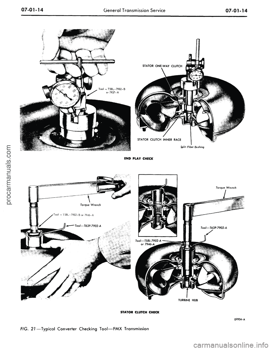
07-01-14
General Transmission Service
07-01-14
STATOR CLUTCH INNER RACE
Splh Fiber Bushing
END PLAY CHECK
Torque
Wrench
Torque
Wrench
Tool -T58L-7902-B or 7946-A
TURBINE HUB
STATOR CLUTCH CHECK
D1934-A
FIG. 21—Typical Converter Checking Tool—FMX Transmissionprocarmanuals.com
Page 312 of 413
07-02-04
C4 Automatic Transmission
07-02-04
The transmission consists essentially
of a torque converter, planetary gear
train, two multiple disc clutches, a
one-way clutch and a hydraulic con-
trol system (Fig. 3).
The only adjustments on the trans-
mission proper are the intermediate
and low-reverse bands.
TRANSMISSION
MANUAL LEVER
2 IN-VEHICLE ADJUSTMENTS
AND
REPAIRS
CONTROL LINKAGE ADJUSTMENTS
The transmission control linkage
adjustments should be performed in
the order in which they appear in this
section of the manual.
THROTTLE AND DOWNSHIFT
LINKAGE ADJUSTMENTS
Adjusting the throttle linkage is im-
portant to be certain the throttle and
kickdown systems are properly adjust-
ed. The kickdown system should come
in when the accelerator is pressed
through detent, and not before detent.
Refer to Group 10 for detailed
throttle and downshift linkage adjust-
ment procedures.
MANUAL LINKAGE
ADJUSTMENTS
Column Shift
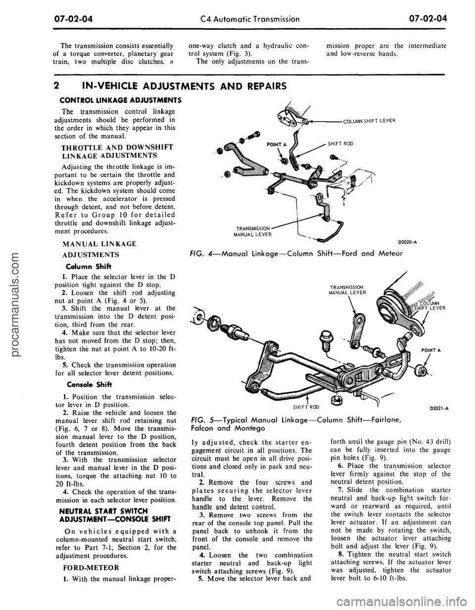
1.
Place the selector lever in the D
position tight against the D stop.
2.
Loosen the shift rod adjusting
nut at point A (Fig. 4 or 5).
3.
Shift the manual lever at the
transmission into the D detent posi-
tion, third from the rear.
4.
Make sure that the selector lever
has not moved from the D stop; then,
tighten the nut at point A to 10-20 ft-
lbs.
5.
Check the transmission operation
for all selector lever detent positions.
Console Shift
1.
Position the transmission selec-
tor lever in D position.
2.
Raise the vehicle and loosen the
manual lever shift rod retaining nut
(Fig. 6, 7 or 8). Move the transmis-
sion manual lever to the D position,
fourth detent position from the back
of the transmission.
3.
With the transmission selector
lever and manual lever in the D posi-
tions,
torque the attaching nut 10 to
20 ft-lbs.
4.
Check the operation of the trans-
mission in each selector lever position.
NEUTRAL START SWITCH
ADJUSTMENT—CONSOLE SHIFT
On vehicles equipped with a
column-mounted neutral start switch,
refer to Part 7-1, Section 2, for the
adjustment procedures.
FORD-METEOR
1.
With the manual linkage proper-
COLUMN SHIFT LEVER
D2020-A
FIG.
4—Manual
Linkage—Column Shift—Ford
and
Meteor
"COLUMN
SHIFT LEVER
POINT
A
SHIFT
ROD
D2021-A
FIG.
5—Typical
Manual Linkage—Column
Shift—Fairlane,
Falcon
and
Montego
ly adjusted, check the starter en-
gagement circuit in all positions. The
circuit must be open in all drive posi-
tions and closed only in park and neu-
tral.
2.
Remove the four screws and
plates securing the selector lever
handle to the lever. Remove the
handle and detent control.
3.
Remove two screws from the
rear of the console top panel. Pull the
panel back to unhook it from the
front of the console and remove the
panel.
4.
Loosen the two combination
starter neutral and back-up light
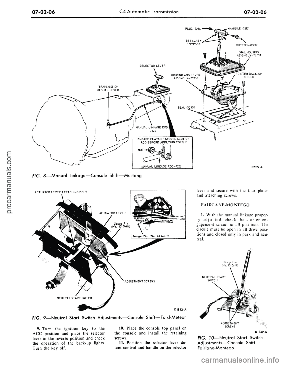
switch attaching screws (Fig. 9).
5.
Move the selector lever back and
forth until the gauge pin (No. 43 drill)
can be fully inserted into the gauge
pin holes (Fig. 9).
6. Place the transmission selector
lever firmly against the stop of the
neutral detent position.
7.
Slide the combination starter
neutral and back-up light switch for-
ward or rearward as required, until
the switch lever contacts the selector
lever actuator. If an adjustment can
not be made by rotating the switch,
loosen the actuator lever attaching
bolt and adjust the lever (Fig. 9).
8. Tighten the neutral start switch
attaching screws. If the actuator lever
was adjusted, tighten the actuator
lever bolt to 6-10 ft-lbs.procarmanuals.com
Page 314 of 413
07-02-06
C4 Automatic Transmission
07-02-06
PLUG-7256
•HANDLE-7217
BUTTON-7C439
DIAL HOUSING
ASSEMBLY-7E034
POINTER BACK-UP
SHIELD
ENGAGE FLATS OF STUD IN SLOT OF
ROD BEFORE APPLYING TORQUE
D2022-A
FIG. 8—Manual Linkage—Console Shift—Mustang
ACTUATOR LEVER ATTACHING BOLT
D1812-A
FIG. 9—Neutral Start Switch Adjustments—Console Shift—Ford-Meteor
9. Turn the ignition key to the
ACC position and place the selector
lever in the reverse position and check
the operation of the back-up lights.
Turn the key off.
10.
Place the console top panel on
the console and install the retaining
screws.
11.
Position the selector lever de-
tent control and handle on the selector
lever and secure with the four plates
and attaching screws.
FAIRLANE-MONTEGO
1.
With the manual linkage proper-
ly adjusted, check the starter en-
gagement circuit in all positions. The
circuit must be open in all drive posi-
tions and closed only in park and neu-
tral.
Gauge Pin
(No.43 Drill)
NEUTRAL START
SWITCH
Dl759-A
70—Neutral Start Switch
Adjustments—Console Shift—
Fairlane-Montegoprocarmanuals.com
Page 315 of 413
07-02-07
C4 Automatic Transmission
07-02-07
2.
Remove the selector lever handle
from the lever.
3.
Remove the trim panel from the
top of the console.
4.
Remove the cover and dial indi-
cator as an assembly.
5.
Remove the four screws that se-
cure the selector lever retainer to the
selector lever housing. Lift the retainer
from the housing.
6. Loosen the two combination
starter neutral and back-up light
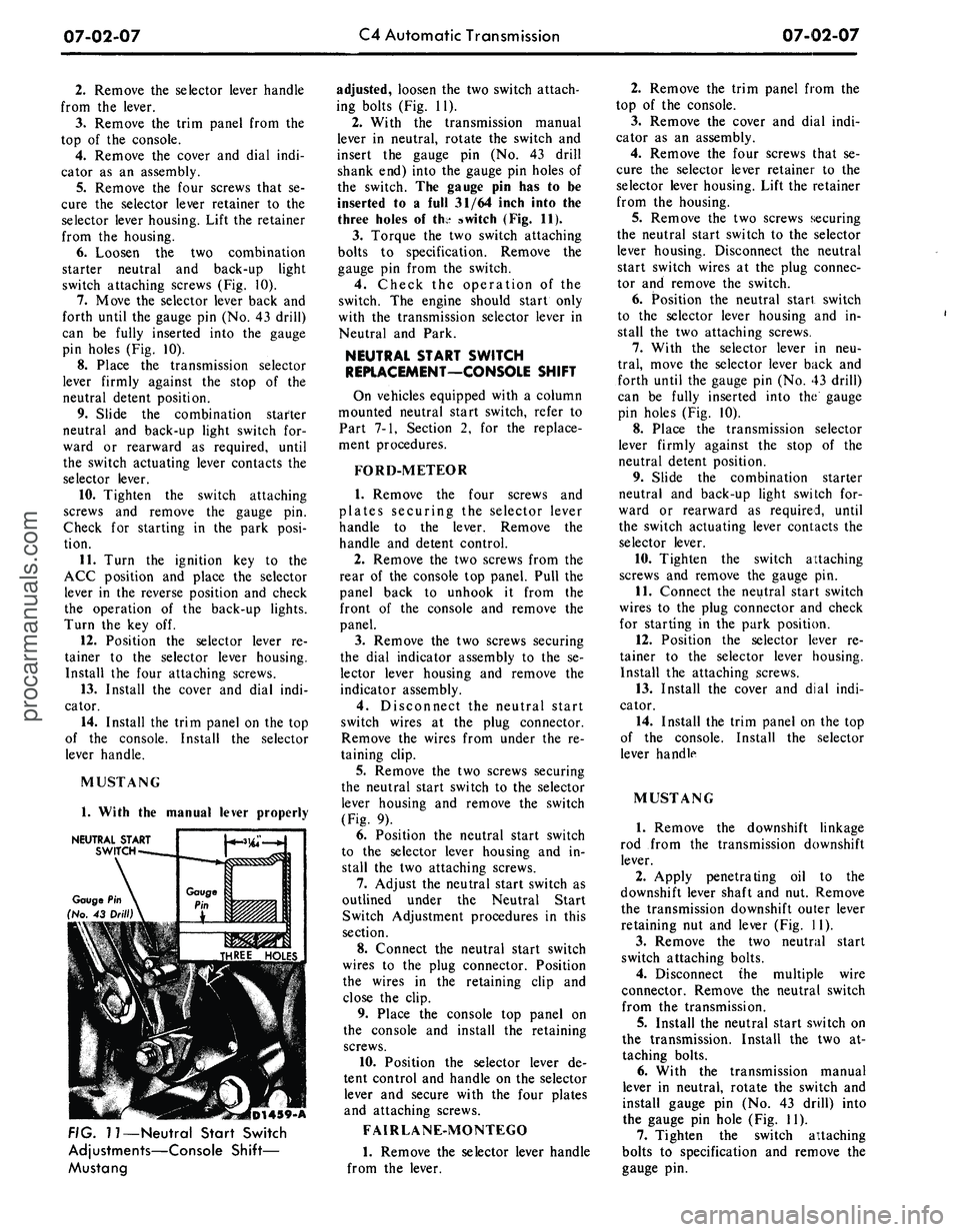
switch attaching screws (Fig. 10).
7.
Move the selector lever back and
forth until the gauge pin (No. 43 drill)
can be fully inserted into the gauge
pin holes (Fig. 10).
8. Place the transmission selector
lever firmly against the stop of the
neutral detent position.
9. Slide the combination starter
neutral and back-up light switch for-
ward or rearward as required, until
the switch actuating lever contacts the
selector lever.
10.
Tighten the switch attaching
screws and remove the gauge pin.
Check for starting in the park posi-
tion.
11.
Turn the ignition key to the
ACC position and place the selector
lever in the reverse position and check
the operation of the back-up lights.
Turn the key off.
12.
Position the selector lever re-
tainer to the selector lever housing.
Install the four attaching screws.
13.
Install the cover and dial indi-
cator.
14.
Install the trim panel on the top
of the console. Install the selector
lever handle.
MUSTANG
1.
With the manual lever properly
NEUTRAL
START
SWITCH
(D1439-A
FIG. 11—Neutral Start Switch
Adjustments—Console Shift—
Mustang
adjusted, loosen the two switch attach-
ing bolts (Fig. 11).
2.
With the transmission manual
lever in neutral, rotate the switch and
insert the gauge pin (No. 43 drill
shank end) into the gauge pin holes of
the switch. The gauge pin has to be
inserted to a full 31/64 inch into the
three holes of the switch (Fig. 11).
3.
Torque the two switch attaching
bolts to specification. Remove the
gauge pin from the switch.
4.
Check the operation of the
switch. The engine should start only
with the transmission selector lever in
Neutral and Park.
NEUTRAL START SWITCH
REPLACEMENT—CONSOLE SHIFT
On vehicles equipped with a column
mounted neutral start switch, refer to
Part 7-1, Section 2, for the replace-
ment procedures.
FORD-METEOR
1.
Remove the four screws and
plates securing the selector lever
handle to the lever. Remove the
handle and detent control.
2.
Remove the two screws from the
rear of the console top panel. Pull the
panel back to unhook it from the
front of the console and remove the
panel.
3.
Remove the two screws securing
the dial indicator assembly to the se-
lector lever housing and remove the
indicator assembly.
4.
Disconnect the neutral start
switch wires at the plug connector.
Remove the wires from under the re-
taining clip.
5.
Remove the two screws securing
the neutral start switch to the selector
lever housing and remove the switch
(Fig. 9).
6. Position the neutral start switch
to the selector lever housing and in-
stall the two attaching screws.
7.
Adjust the neutral start switch as
outlined under the Neutral Start
Switch Adjustment procedures in this
section.
8. Connect the neutral start switch
wires to the plug connector. Position
the wires in the retaining clip and
close the clip.
9. Place the console top panel on
the console and install the retaining
screws.
10.
Position the selector lever de-
tent control and handle on the selector
lever and secure with the four plates
and attaching screws.
FAIRLANE-MONTEGO
1.
Remove the selector lever handle
from the lever.
2.
Remove the trim panel from the
top of the console.
3.
Remove the cover and dial indi-
cator as an assembly.
4.
Remove the four screws that se-
cure the selector lever retainer to the
selector lever housing. Lift the retainer
from the housing.
5.
Remove the two screws securing
the neutral start switch to the selector
lever housing. Disconnect the neutral
start switch wires at the plug connec-
tor and remove the switch.
6. Position the neutral start switch
to the selector lever housing and in-
stall the two attaching screws.
7.
With the selector lever in neu-
tral,
move the selector lever back and
forth until the gauge pin (No. 43 drill)
can be fully inserted into the gauge
pin holes (Fig. 10).
8. Place the transmission selector
lever firmly against the stop of the
neutral detent position.
9. Slide the combination starter
neutral and back-up light switch for-
ward or rearward as required, until
the switch actuating lever contacts the
selector lever.
10.
Tighten the switch attaching
screws and remove the gauge pin.
11.
Connect the neutral start switch
wires to the plug connector and check
for starting in the park position.
12.
Position the selector lever re-
tainer to the selector lever housing.
Install the attaching screws.
13.
Install the cover and dial indi-
cator.
14.
Install the trim panel on the top
of the console. Install the selector
lever handle
MUSTANG
1.
Remove the downshift linkage
rod from the transmission downshift
lever.
2.
Apply penetrating oil to the
downshift lever shaft and nut. Remove
the transmission downshift outer lever
retaining nut and lever (Fig. 11).
3.
Remove the two neutral start
switch attaching bolts.
4.
Disconnect the multiple wire
connector. Remove the neutral switch
from the transmission.
5.
Install the neutral start switch on
the transmission. Install the two at-
taching bolts.
6. With the transmission manual
lever in neutral, rotate the switch and
install gauge pin (No. 43 drill) into
the gauge pin hole (Fig. 11).
7.
Tighten the switch attaching
bolts to specification and remove the
gauge pin.procarmanuals.com
Page 316 of 413
07-02-08
C4 Automatic Transmission
07-02-08
8. Install the outer downshift lever
and attaching nut, and torque the nut
to specification. Install the downshift
linkage rod to the downshift lever.
9. Install the switch wires. Connect
the wire multiple connector. Check
the operation of the switch in each de-
tent position. The engine should start
only with the transmission selector
lever in N (neutral) and P (park).
SELECTOR LEVER
REPLACEMENT—CONSOLE SHIFT
FORD-METEOR
1.
Raise the vehicle and disconnect
the link assembly from the selector
lever arm (Fig. 6).
2.
Lower the vehicle. Remove the
four screws and plates securing the se-
lector lever handle to the lever. Re-
move the handle and detent control.
3.
Remove the two screws from the
rear of the console top panel. Pull the
panel back to unhook it from the
front of the console and remove the
panel.
4.
Disconnect the neutral start
switch wires at the plug connector.
Disconnect the bulb socket from the
quadrant.
5.
Remove the four bolts that at-
tach the selector lever housing to the
floor pan and remove the selector
lever and housing.
6. Position the new selector lever
and housing assembly on the floor pan
and install the attaching bolts.
7.
Connect the bulb socket to the
quadrant and the neutral start switch
wires to the plug connector.
8. Raise the vehicle and secure the
link assembly to the selector lever arm
with the bushing, insulator, flat wash-
er and cotter pin (Fig. 6). Lower the
vehicle.
9. Place the console top panel on
the console and install the retaining
screws.
10.
Position the selector lever de-
tr*rtt control and handle on the selector
lever and secure with the four plates
and attaching screws.
FAIRLANE-MONTEGO
1.
Raise the vehicle on a hoist or
jack stands.
2.
Remove the retainer that secures
the manual linkage rod to the lower
end of the manual lever (Fig. 7).
3.
Remove the flat washer and two
insulator washers and disconnect the
rod from the arm.
4.
Working from inside of the vehi-
cle,
remove the selector lever handle
attaching screw. Lift the handle off
the selector lever.
DETENT PAWL
LOCK NUT
DETENT PAWL
ADJUSTMENT SCREW
DETENT PLATE
D 1644-A
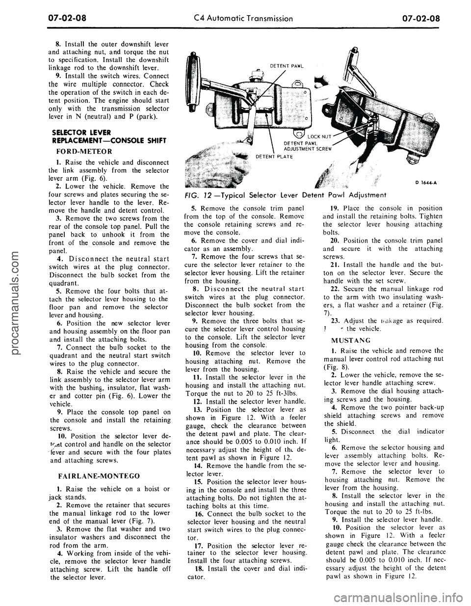
FIG. 72—Typical Selector Lever Detent Pawl Adjustment
5.
Remove the console trim panel
from the top of the console. Remove
the console retaining screws and re-
move the console.
6. Remove the cover and dial indi-
cator as an assembly.
7.
Remove the four screws that se-
cure the selector lever retainer to the
selector lever housing. Lift the retainer
from the housing.
8. Disconnect the neutral start
switch wires at the plug connector.
Disconnect the bulb socket from the
selector lever housing.
9. Remove the three bolts that se-
cure the selector lever control housing
to the console. Lift the selector lever
housing from the console.
10.
Remove the selector lever to
housing attaching nut. Remove the
lever from the housing.
11.
Install the selector lever in the
housing and install the attaching nut.
Torque the nut to 20 to 25 ft-31bs.
12.
Install the selector lever handle.
13.
Position the selector lever as
shown in Figure 12. With a feeler
gauge, check the clearance between
the detent pawl and plate. The clear-
ance should be 0.005 to 0.010 inch. If
necessary adjust the height of the de-
tent pawl as shown in Figure 12.
14.
Remove the handle from the se-
lector lever.
15.
Position the selector lever hous-
ing in the console and install the three
attaching bolts. Do not tighten the at-
taching bolts at this time.
16.
Connect the bulb socket to the
selector lever housing and the neutral
start switch wires to the plug connec-
tor.
17.
Position the selector lever re-
tainer to the selector lever housing.
Install the four attaching screws.
18.
Install the cover and dial indi-
cator.
19.
Place the console in position
and install the retaining bolts. Tighten
the selector lever housing attaching
bolts.
20.
Position the console trim panel
and secure it with the attaching
screws.
21.
Install the handle and the but-
ton on the selector lever. Secure the
handle with the set screw.
22.
Secure the manual linkage rod
to the arm with two insulating wash-
ers,
a flat washer and a retainer (Fig.
7).
23.
Adjust the linkage as required.
J r the vehicle.
MUSTANG
1.
Raise the vehicle and remove the
manual lever control rod attaching nut
(Fig. 8).
2.
Lower the vehicle, remove the se-
lector lever handle attaching screw.
3.
Remove the dial housing attach-
ing screws and the housing.
4.
Remove the two pointer back-up
shield attaching screws and remove
the shield.
5.
Disconnect the dial indicator
light.
6. Remove the selector housing and
lever assembly attaching bolts. Re-
move the selector lever and housing.
7.
Remove the selector lever to
housing attaching nut. Remove the
lever from the housing.
8. Install the selector lever in the
housing and install the attaching nut.
Torque the nut to 20 to 25 ft-lbs.
9. Install the selector lever handle.
10.
Position the selector lever as
shown in Figure 12. With a feeler
gauge check the clearance between the
detent pawl and plate. The clearance
should be 0.005 to 0.010 inch. If nec-
essary adjust the height of the detent
pawl as shown in Figure 12.procarmanuals.com
Page 317 of 413
07-02-09
C4 Automatic Transmission
07-02-09
11.
Remove the handle from the se-
lector lever.
12.
Install the selector housing and
lever assembly as shown in Figure 8.
Torque the attaching bolts 4-6 ft-lbs.
13.
Connect the dial indicator light.
14.
Install the pointer back-up
shield on the housing and lever assem-
bly.
15.
Install the dial housing and
tighten the attaching screws.
16.
Install the selector lever handle
and tighten the attaching screw.
17.
Position the selector lever in the
D position.
18.
Raise the vehicle. Install the
transmission manual lever rod to the
selector lever. Adjust the manual link-
age.
19.
Lower the vehicle and check the
transmission operation in each selo:c-
tor lever detent position.
BAND ADJUSTMENT
INTERMEDIATE BAND
1.
Clean all the dirt from the band
adjusting screw area. Remove and dis-
card the locknut.
2.
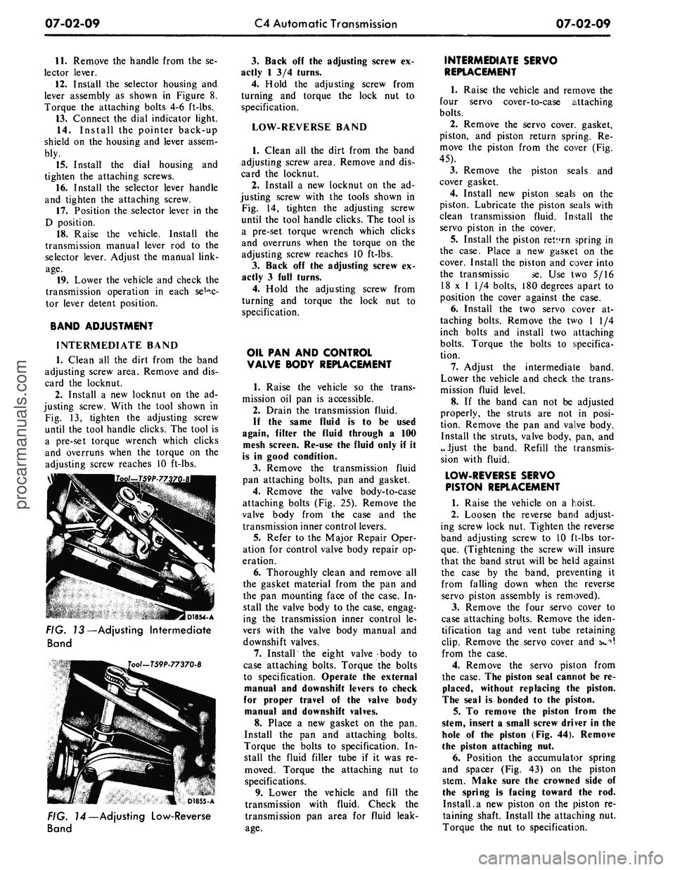
Install a new locknut on the ad-
justing screw. With the tool shown in
Fig. 13, tighten the adjusting screw
until the tool handle clicks. The tool is
a pre-set torque wrench which clicks
and overruns when the torque on the
adjusting screw reaches 10 ft-lbs.
I D1854-A
FIG. 13—Adjusting Intermediate
Band
Tool-T59P-77370-B
D1855-A
FIG. 14—Adjusting Low-Reverse
Band
3.
Back off the adjusting screw ex-
actly 1 3/4 turns.
4.
Hold the adjusting screw from
turning and torque the lock nut to
specification.
LOW-REVERSE BAND
1.
Clean all the dirt from the band
adjusting screw area. Remove and dis-
card the locknut.
2.
Install a new locknut on the ad-
justing screw with the tools shown in
Fig. 14, tighten the adjusting screw
until the tool handle clicks. The tool is
a pre-set torque wrench which clicks
and overruns when the torque on the
adjusting screw reaches 10 ft-lbs.
3.
Back off the adjusting screw ex-
actly 3 full turns.
4.
Hold the adjusting screw from
turning and torque the lock nut to
specification.
OIL PAN AND CONTROL
VALVE BODY REPLACEMENT
1.
Raise the vehicle so the trans-
mission oil pan is accessible.
2.
Drain the transmission fluid.
If the same fluid is to be used
again, filter the fluid through a 100
mesh screen. Re-use the fluid only if it
is in good condition.
3.
Remove the transmission fluid
pan attaching bolts, pan and gasket.
4.
Remove the valve body-to-case
attaching bolts (Fig. 25). Remove the
valve body from the case and the
transmission inner control levers.
5.
Refer to the Major Repair Oper-
ation for control valve body repair op-
eration.
6. Thoroughly clean and remove all
the gasket material from the pan and
the pan mounting face of the case. In-
stall the valve body to the case, engag-
ing the transmission inner control le-
vers with the valve body manual and
downshift valves.
7.
Install the eight valve body to
case attaching bolts. Torque the bolts
to specification. Operate the external
manual and downshift levers to check
for proper travel of the valve body
manual and downshift valves.
8. Place a new gasket on the pan.
Install the pan and attaching bolts.
Torque the bolts to specification. In-
stall the fluid filler tube if it was re-
moved. Torque the attaching nut to
specifications.
9. Lower the vehicle and fill the
transmission with fluid. Check the
transmission pan area for fluid leak-
age.
INTERMEDIATE SERVO
REPLACEMENT
1.
Raise the vehicle and remove the
four servo cover-to-case attaching
bolts.
2.
Remove the servo cover, gasket,
piston, and piston return spring. Re-
move the piston from the cover (Fig.
45).
3.
Remove the piston seals and
cover gasket.
4.
Install new piston seals on the
piston. Lubricate the piston seals with
clean transmission fluid. Install the
servo piston in the cover.
5.
Install the piston retvrn spring in
the case. Place a new gasicet on the
cover. Install the piston and cover into
the transmissic se. Use two 5/16
18 x 1 1/4 bolts, 180 degrees apart to
position the cover against the case.
6. Install the two servo cover at-
taching bolts. Remove the two 1 1/4
inch bolts and install two attaching
bolts.
Torque the bolts to specifica-
tion.
7.
Adjust the intermediate band.
Lower the vehicle and check the trans-
mission fluid level.
8. If the band can not be adjusted
properly, the struts are not in posi-
tion. Remove the pan and valve body.
Install the struts, valve body, pan, and
adjust the band. Refill the transmis-
sion with fluid.
LOW-REVERSE SERVO
PISTON REPLACEMENT
1.
Raise the vehicle on a hoist.
2.
Loosen the reverse band adjust-
ing screw lock nut. Tighten the reverse
band adjusting screw to 10 ft-lbs tor-
que.
(Tightening the screw will insure
that the band strut will be held against
the case by the band, preventing it
from falling down when the reverse
servo piston assembly is removed).
3.
Remove the four servo cover to
case attaching bolts. Remove the iden-
tification tag and vent tube retaining
clip.
Remove the servo cover and s»»^
from the case.
4.
Remove the servo piston from
the case. The piston seal cannot be re-
placed, without replacing the piston.
The seal is bonded to the piston.
5. To remove the piston from the
stem, insert a small screw driver in the
hole of the piston (Fig. 44). Remove
the piston attaching nut.
6. Position the accumulator spring
and spacer (Fig. 43) on the piston
stem. Make sure the crowned side of
the spring is facing toward the rod.
Install.a new piston on the piston re-
taining shaft. Install the attaching nut.
Torque the nut to specification.procarmanuals.com