GEELY CK 2008 Service Manual
Manufacturer: GEELY, Model Year: 2008,
Model line: CK,
Model: GEELY CK 2008
Pages: 392, PDF Size: 38.86 MB
GEELY CK 2008 Service Manual
CK 2008
GEELY
GEELY
https://www.carmanualsonline.info/img/58/57159/w960_57159-0.png
GEELY CK 2008 Service Manual
Trending: power steering fluid, airbag off, oil capacity, ground clearance, battery capacity, engine overheat, battery replacement
Page 41 of 392
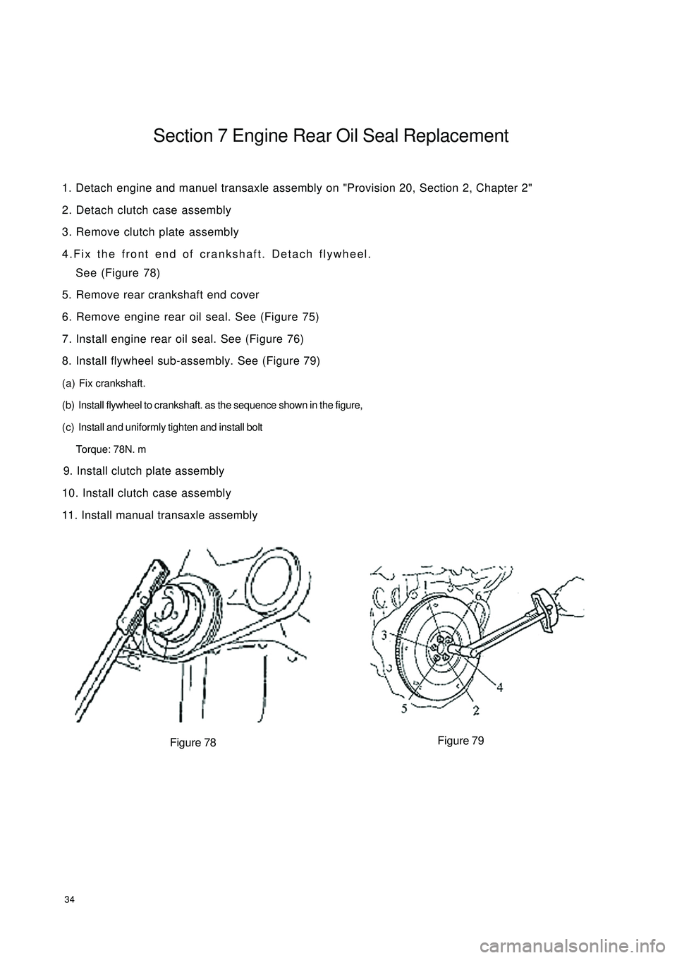
34Section 7 Engine Rear Oil Seal Replacement1. Detach engine and manuel transaxle assembly on "Provision 20, Section 2, Chapter 2"
2. Detach clutch case assembly
3. Remove clutch plate assembly
4.Fix the front end of crankshaft. Detach flywheel.
See (Figure 78)
5. Remove rear crankshaft end cover
6. Remove engine rear oil seal. See (Figure 75)
7. Install engine rear oil seal. See (Figure 76)
8. Install flywheel sub-assembly. See (Figure 79)
(a) Fix crankshaft.
(b) Install flywheel to crankshaft. as the sequence shown in the figure,
(c) Install and uniformly tighten and install bolt
Torque: 78N. m
9. Install clutch plate assembly
10. Install clutch case assembly
11. Install manual transaxle assembly
Figure 78Figure 79
Page 42 of 392
35Chapter 3 Lubrication System
(MR479Q, MR479QA, MR481QA)Section 1 Oil Pressure Gage Sensor Replacement1. Check oil level
Warm up the engine. Check the dipstick to ensure oil level between "L" and "F" after engine stopped
5 minutes. Check for leakage if it is too low. Fill oil to "F.
2. Check oil for deterioration. Water entry, discolor and dilution. Replace oil if it is obviously
deteriorated.
3. Detach oil pressure sensor assembly. See (Figure 80)
4. Install oil pressure gage sensor. See (Figure 81) Start engine to
normal operation temperature.
5. Check for oil pressure
6. Smear adhesive on 2 or 3 threads of the oil pressure sensor.
Install oil pressure sensor. See (Figure 82)
Figure 81
Figure 82Figure 80
Page 43 of 392
36Section 2 Oil Pump Assembly Replacement1. Remove timing belt
2. Remove timing belt idler sub-assembly
3. Detach crankshaft timing pulley. See (Figure 74)
4. Remove the dipstick guide
5. Detach oil sump sub-assembly. See (Figure 83)
6. Detach oil strainer sub-assembly. See (Figure 84)
7. Detach oil pump assembly. See (Figure 85)
8. Remove oil pump oil seal
9. Install oil pump oil seal
10. Install oil pump assembly
11. Install oil strainer sub-assembly
12. Install oil sump assembly. See (Figure 86)
Figure 84
Figure 85Figure 83Figure 86
Page 44 of 392
3713. Install the dipstick guide. See (Figure 87)
14. Install crankshaft timing pulley. See (Figure 77)
15. Install timing belt idler sub-assembly No.1
16. Install timing belt
17. Fill in engine oil
18. Check oil for leakage
Figure 87
Page 45 of 392
38Section 3 Oil Filter Replacement1. Detach oil filter sub-assembly. See (Figure 88)
2. Install oil filter sub-assembly. See (Figure 89)
Figure 88 Figure 89
3. Install drain plug
Clean and use new washer to install drain plug.
Torque: 54N. m
4. Oil fill
Capacity:
Oil refill amount with the filter replaced: 3.0L
Oil refill amount without the filter dry fill replaced: 2.80L
Dry fill: 3.3L
5. Check oil for leakage
Page 46 of 392
39Section 4 Starter Replacement1. Detach starter assembly. See (Figure 90)
2. Install starter assembly
Torque:
Bolt 37N. m
Figure 90
Page 47 of 392
40Section 5 Generator Replacement1. Detach V-belt of generator
2. Detach generator assembly
(a) Disconnect wire joint of generator.
(b) Remove wire of generator.
(c) Disconnect oil pressure switch interface.
(d) Disconnect A/C compressor switch connector.
(e) Open wire clips.
(f) Detach 2 bolts and generator.
3. Install generator assembly
Torque:
M12 bolt 18N. m
M14 bolt 58N. m
4. Transmit belt tilt and tension state inspection
Page 48 of 392

41Chapter 4 Fuel System
(MR7131A, MR7151A, MR7161A)Section 1 Check Fuel System Pressure1. Remove the fuel tank from the vehicle
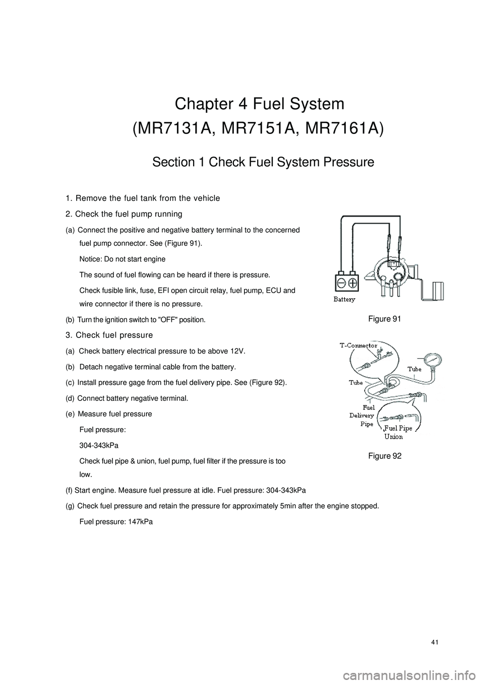
2. Check the fuel pump running
(a) Connect the positive and negative battery terminal to the concerned
fuel pump connector. See (Figure 91).
Notice: Do not start engine
The sound of fuel flowing can be heard if there is pressure.
Check fusible link, fuse, EFI open circuit relay, fuel pump, ECU and
wire connector if there is no pressure.
(b) Turn the ignition switch to "OFF" position.
3. Check fuel pressure
(a) Check battery electrical pressure to be above 12V.
(b) Detach negative terminal cable from the battery.
(c) Install pressure gage from the fuel delivery pipe. See (Figure 92).
(d) Connect battery negative terminal.
(e) Measure fuel pressure
Fuel pressure:
304-343kPa
Check fuel pipe & union, fuel pump, fuel filter if the pressure is too
low.
(f) Start engine. Measure fuel pressure at idle. Fuel pressure: 304-343kPa
(g) Check fuel pressure and retain the pressure for approximately 5min after the engine stopped.
Fuel pressure: 147kPaFigure 91Figure 92
Page 49 of 392
42Section 2 Fuel Pump Inspection1. Fuel pump
(a) Check fuel pump resistance, 0.2~3.0 at 20°. Replace fuel pump if the resistance is not as specified.
See (Figure 93)
(b) Fuel pump running:
Check fuel pump by connecting with battery. Replace fuel pump or wire if the running is not as specified.
See (Figure 94).
The test should be conducted within 10s to prevent coil from damage.
2. Fuel injector assembly
Injection Volume: 40~50cm3/s
Error between each injector: less than 10 cm3Replace injector if the injection volume is not as specified.
(a) Check for leakage: Disconnect the cable from the battery. The fuel drop/min is no more than 1 drop.
Figure 93 Figure 94 Ohmmeter
Battery Ω
Page 50 of 392
43Section 3 Fuel Injector Replacement1. Check fuel for ejection.
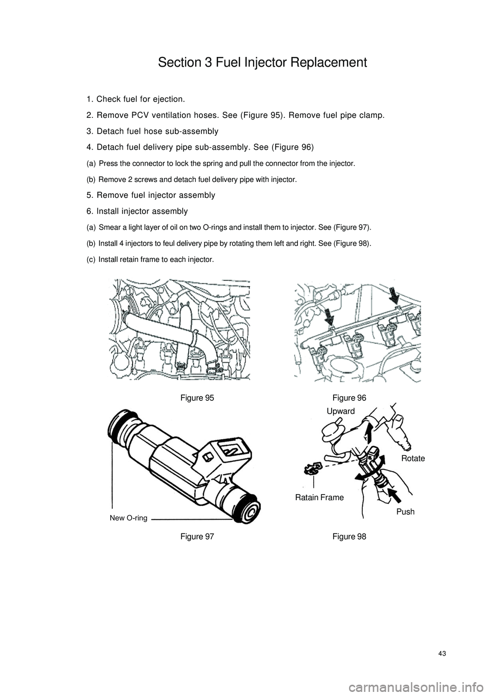
2. Remove PCV ventilation hoses. See (Figure 95). Remove fuel pipe clamp.
3. Detach fuel hose sub-assembly
4. Detach fuel delivery pipe sub-assembly. See (Figure 96)
(a) Press the connector to lock the spring and pull the connector from the injector.
(b) Remove 2 screws and detach fuel delivery pipe with injector.
5. Remove fuel injector assembly
6. Install injector assembly
(a) Smear a light layer of oil on two O-rings and install them to injector. See (Figure 97).
(b) Install 4 injectors to feul delivery pipe by rotating them left and right. See (Figure 98).
(c) Install retain frame to each injector.
Figure 95 Figure 96
Figure 97 Figure 98New O-ringUpward
Ratain Frame
PushRotate
Trending: diagram, trunk, coolant reservoir, transmission, steering wheel adjustment, alarm, change wheel


