GEELY MK 2008 Workshop Manual
Manufacturer: GEELY, Model Year: 2008, Model line: MK, Model: GEELY MK 2008Pages: 416, PDF Size: 25.19 MB
Page 301 of 416

Inspection item
V
V
V
V
V
Visual inspection
Visual inspection
Visual inspection
Visual inspection
V
V
ohm
k ohm
MV/Hz
MV/Hz
MV/Hz
MV/Hz Storage battery voltage (motor)
Storage battery voltage
(Solenoid valve)
Power supply insulating property
Earth insulating property
Supply voltage
ABS warning lamp
Brake light switch function pedal
is not stepped down
Brake light switch function pedal
is stepped down
Diagnostic interface
Left front wheel speed sensor
resistance value
Right front wheel speed sensor
resistance value
Left rear wheel speed sensor
resistance value
Right rear wheel speed sensor
resistance value
Left front wheel sensor output
voltage value
Right front wheel sensor output
voltage value
Left rear wheel sensor output
voltage value
Right rear wheel sensor output
voltage value
Speed sensor output voltage ratio10.1 ~ 14.5
10.1 ~ 14.5
0.00 ~ 0.5
0.00 ~ 0.5
10.1 ~ 14.5
Warning lamp goes out
Warning lamp illuminates
Warning lamp goes out
Warning lamp illuminates
for about 1.7s,then goes out
0.0 ~ 0.5
10.0 ~ 14.5
0.0 ~ 0.5
1.2 ~ 1.3
1.2 ~ 1.3
1.0 ~ 1.3
1.0 ~ 1.3
3.4 ~ 14.8
3.4 ~ 14.8
>12.2
>12.2 1-47
32-16
4-16
16-47
4-16
ECU is not
connected
Connect ECU
16-41
16-41
Diagnosis joint
K and 7
45-46
33-34
37-36
42-43
45-46
33-34
37-36
42-43 OFF
OFF
OFF
OFF
ON
OFF
ON
OFF
ON
ON
ON
OFF
OFF
OFF
OFF
OFF
OFF
OFF
OFF
OFF
Maximum peak to peak value voltage
Minimum peak to peak value voltage2III. ABS system inspectionMK-60 ABS system -ABS System Check5-114Ignition switchpositionBinding post Standard value
Unitk ohmk ohmk ohm
Page 302 of 416
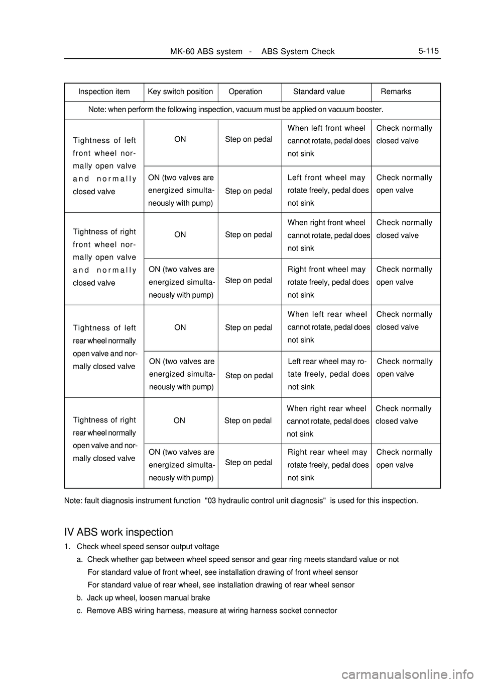
Inspection item
Note: when perform the following inspection, vacuum must be applied on vacuum booster.Tightness of left
front wheel nor-
mally open valve
and normally
closed valveON
ON (two valves are
energized simulta-
neously with pump)Step on pedal
Step on pedalWhen left front wheel
cannot rotate, pedal does
not sinkCheck normally
closed valve
Left front wheel may
rotate freely, pedal does
not sinkCheck normally
open valveTightness of right
front wheel nor-
mally open valve
and normally
closed valveON
ON (two valves are
energized simulta-
neously with pump)Step on pedal
Step on pedalWhen right front wheel
cannot rotate, pedal does
not sinkCheck normally
closed valve
Right front wheel may
rotate freely, pedal does
not sinkCheck normally
open valveTightness of left
rear wheel normally
open valve and nor-
mally closed valveON
ON (two valves are
energized simulta-
neously with pump)Step on pedal
Step on pedalWhen left rear wheel
cannot rotate, pedal does
not sinkCheck normally
closed valve
Left rear wheel may ro-
tate freely, pedal does
not sinkCheck normally
open valveTightness of right
rear wheel normally
open valve and nor-
mally closed valveON
ON (two valves are
energized simulta-
neously with pump)Step on pedal
Step on pedalWhen right rear wheel
cannot rotate, pedal does
not sinkCheck normally
closed valve
Right rear wheel may
rotate freely, pedal does
not sinkCheck normally
open valve
Note: fault diagnosis instrument function "03 hydraulic control unit diagnosis" is used for this inspection.MK-60 ABS system -ABS System Check5-115Key switch position Operation Standard value RemarksIV ABS work inspection1. Check wheel speed sensor output voltage
a. Check whether gap between wheel speed sensor and gear ring meets standard value or not
For standard value of front wheel, see installation drawing of front wheel sensor
For standard value of rear wheel, see installation drawing of rear wheel sensor
b. Jack up wheel, loosen manual brake
c. Remove ABS wiring harness, measure at wiring harness socket connector
Page 303 of 416
Section3 Removal and InstallationI. Precautions for removal and installation1. Firstly use diagnostic instrument to find out source of trouble, then repair.
2. Repair front prior use excluding mineral oil of detergent will surface clean Neatness ; repair when should note
before repair, use detergent without mineral oil to wipe off surface; pay attention to cleaning during repair, only
use rag without wool to wipe removed components.
3. Only use original factory spare parts, and new spare parts could only be unpacked just before installation.
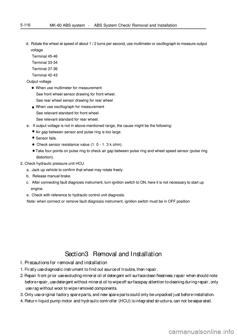
4. Return liquid pump motor and hydraulic controller (HCU) is integrated structure, can not be separated.MK-60 ABS system -ABS System Check/ Removal and Installation5-116 d. Rotate the wheel at speed of about 1 / 2 turns per second, use multimeter or oscillograph to measure output
voltage
Terminal 45-46
Terminal 33-34
Terminal 37-36
Terminal 42-43
Output voltage
When use multimeter for measurement
See front wheel sensor drawing for front wheel.
See rear wheel sensor drawing for rear wheel
When use oscillograph for measurement
See relevant standard for front wheel.
See relevant standard for rear wheel.
e. If output voltage is not in above-mentioned range, the cause might be the following:
Air gap between sensor and pulse ring is too large.
Sensor fails.
Check sensor resistance value (1. 0 - 1. 3 k ohm).
Take four points on pulse ring to check air gap between pulse ring and wheel speed sensor (pulse ring
distortion).
2. Check hydraulic pressure unit HCU
a. Jack up vehicle to confirm that wheel may rotate freely.
b. Release manual brake.
c. After connecting fault diagnosis instrument, turn ignition switch to ON, here it is not necessary to start up
engine.
e. Check with reference to hydraulic control unit diagnosis.
Note: when connect or remove fault diagnosis instrument, ignition switch must be in OFF position
Page 304 of 416
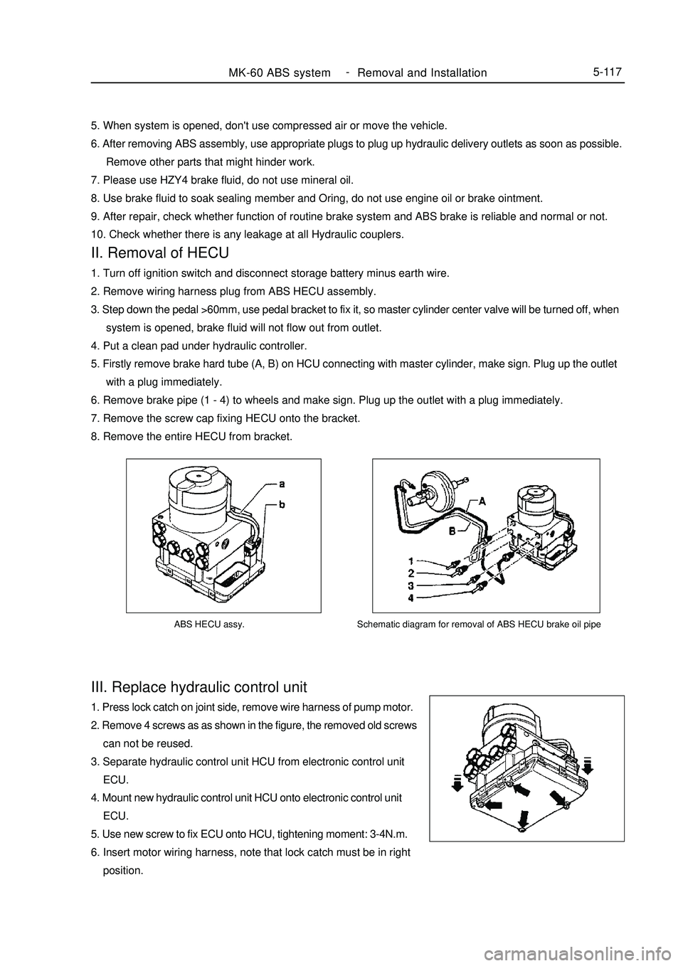
ABS HECU assy.III. Replace hydraulic control unit1. Press lock catch on joint side, remove wire harness of pump motor.
2. Remove 4 screws as as shown in the figure, the removed old screws
can not be reused.
3. Separate hydraulic control unit HCU from electronic control unit
ECU.
4. Mount new hydraulic control unit HCU onto electronic control unit
ECU.
5. Use new screw to fix ECU onto HCU, tightening moment: 3-4N.m.
6. Insert motor wiring harness, note that lock catch must be in right
position.MK-60 ABS system -
Removal and Installation5-117Schematic diagram for removal of ABS HECU brake oil pipe5. When system is opened, don't use compressed air or move the vehicle.
6. After removing ABS assembly, use appropriate plugs to plug up hydraulic delivery outlets as soon as possible.
Remove other parts that might hinder work.
7. Please use HZY4 brake fluid, do not use mineral oil.
8. Use brake fluid to soak sealing member and Oring, do not use engine oil or brake ointment.
9. After repair, check whether function of routine brake system and ABS brake is reliable and normal or not.
10. Check whether there is any leakage at all Hydraulic couplers.II. Removal of HECU1. Turn off ignition switch and disconnect storage battery minus earth wire.
2. Remove wiring harness plug from ABS HECU assembly.
3. Step down the pedal >60mm, use pedal bracket to fix it, so master cylinder center valve will be turned off, when
system is opened, brake fluid will not flow out from outlet.
4. Put a clean pad under hydraulic controller.
5. Firstly remove brake hard tube (A, B) on HCU connecting with master cylinder, make sign. Plug up the outlet
with a plug immediately.
6. Remove brake pipe (1 - 4) to wheels and make sign. Plug up the outlet with a plug immediately.
7. Remove the screw cap fixing HECU onto the bracket.
8. Remove the entire HECU from bracket.
Page 305 of 416
V. Reinstallation of ABS assemblyNote: plug of hydraulic opening on ABS assembly may be removed only when brake hard tube is to be installed,
so as to avoid foreign body entering brake system
1. Mount ABS assembly to bracket and tighten it, moment is 20~24 N.m.
2. Remove the plug on hydraulic opening, mount brake hard tube, confirm that hard tube connection is correct.
3. Mount brake hard tube to master cylinder.
4. Tightening moment for assembly of brake hard tube is 12~16N.m (M10 x 1) and 15~18 N.m (M12 x 1).
5. Fill new brake fluid into tank until liquid level reaches MAX place, use specified method to exhaust.
6. Turn ignition switch to ON, ABS warning lamp must illuminate for 1. 7s, then go out.
7. Eliminate fault code memory, reread to see whether there is any fault code.
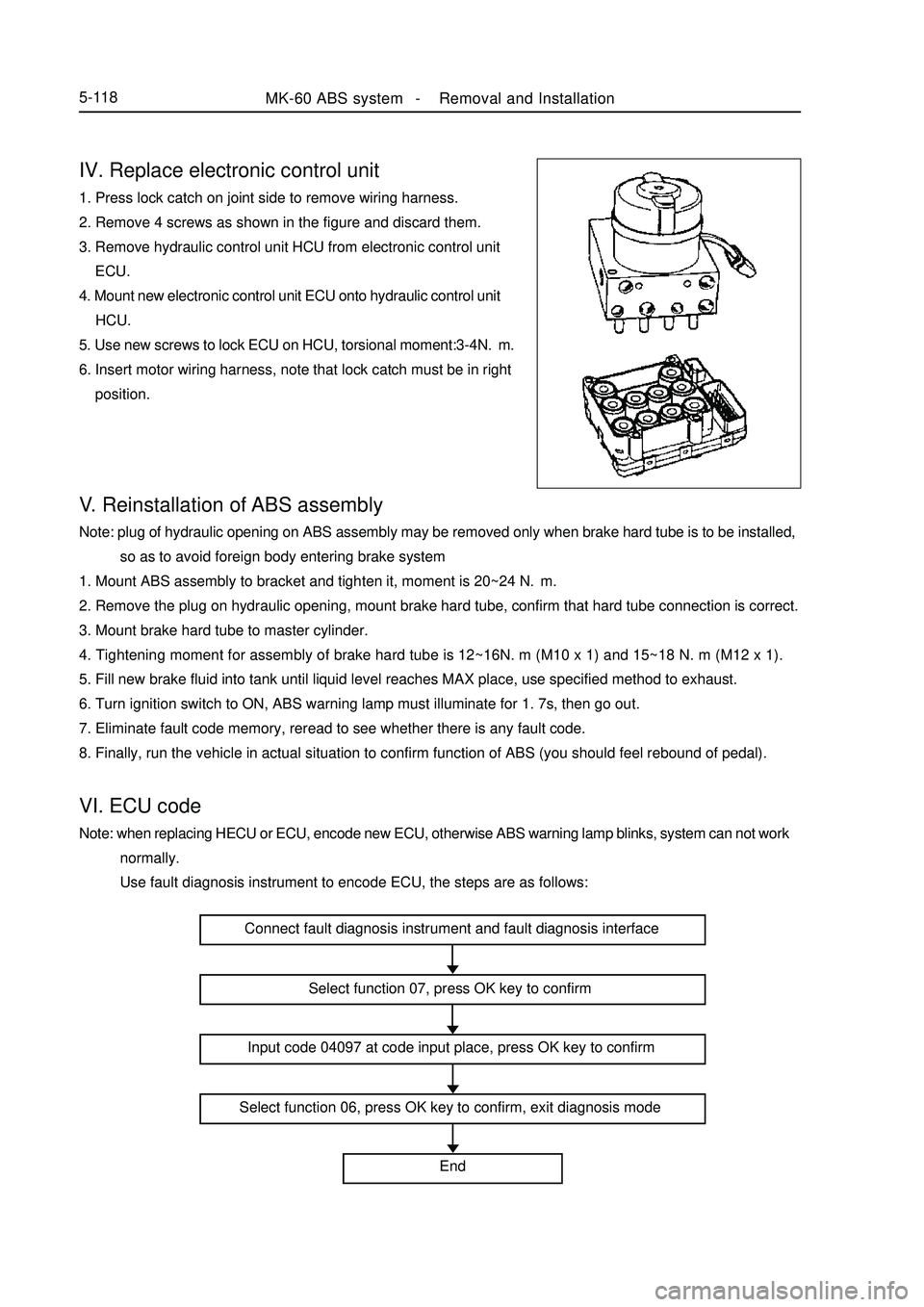
8. Finally, run the vehicle in actual situation to confirm function of ABS (you should feel rebound of pedal).VI. ECU codeNote: when replacing HECU or ECU, encode new ECU, otherwise ABS warning lamp blinks, system can not work
normally.
Use fault diagnosis instrument to encode ECU, the steps are as follows:IV. Replace electronic control unit1. Press lock catch on joint side to remove wiring harness.
2. Remove 4 screws as shown in the figure and discard them.
3. Remove hydraulic control unit HCU from electronic control unit
ECU.
4. Mount new electronic control unit ECU onto hydraulic control unit
HCU.
5. Use new screws to lock ECU on HCU, torsional moment:3-4N.m.
6. Insert motor wiring harness, note that lock catch must be in right
position.MK-60 ABS system -Removal and Installation5-118Connect fault diagnosis instrument and fault diagnosis interface
Select function 07, press OK key to confirm
Input code 04097 at code input place, press OK key to confirm
Select function 06, press OK key to confirm, exit diagnosis mode
End
Page 306 of 416
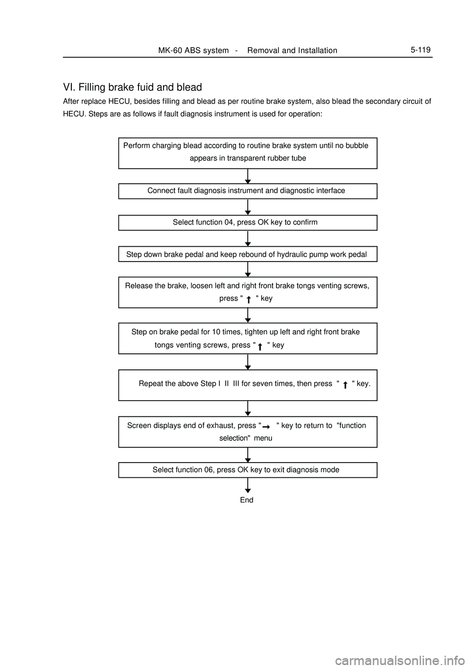
VI. Filling brake fuid and bleadAfter replace HECU, besides filling and blead as per routine brake system, also blead the secondary circuit of
HECU. Steps are as follows if fault diagnosis instrument is used for operation:MK-60 ABS system -Removal and Installation5-119Perform charging blead according to routine brake system until no bubble
appears in transparent rubber tube
Connect fault diagnosis instrument and diagnostic interface
Select function 04, press OK key to confirm
Step down brake pedal and keep rebound of hydraulic pump work pedal
Release the brake, loosen left and right front brake tongs venting screws,
press " " key
Step on brake pedal for 10 times, tighten up left and right front brake
tongs venting screws, press " " key
Repeat the above Step I II III for seven times, then press " " key.
Screen displays end of exhaust, press " " key to return to "function
selection" menu
Select function 06, press OK key to exit diagnosis modeEnd
Page 307 of 416
Fault symptom
Flameout, poor idle speedChapter 9 Engine EFI SystemI. Outline This system includes sensor that detects engine functioning. Engine ECU utilizes sensors installed at differ-
ent parts of engine to measure various working parameters of engine, accurately control oil injection quantity
according to control procedure set in engine electronic control unit, so engine could work in optimum mode
under various operating conditions, i. e. optimal power output, the most economical oil consumption, optimal
exhaust emissions. Engine ECU is capable of start up control, idle speed closed-loop control, air fuel ratio
closed-loop control, canister control, transient operation control, angle of ignition control, knocking control, air
conditioning control, coasting fuel cutoff and overspeed fuel cutoff control, ternary catalyst heating and protec-
tion control, system self-diagnosis etc.II. Inspection of control element1. Manifold intake pressure temperature sensor
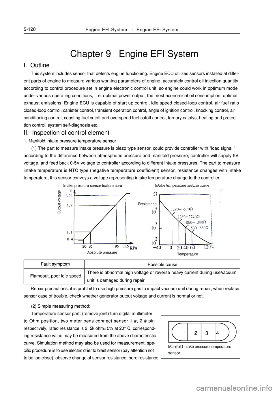
(1) The part to measure intake pressure is piezo type sensor, could provide controller with "load signal "
according to the difference between atmospheric pressure and manifold pressure; controller will supply 5V
voltage, and feed back 0-5V voltage to controller according to different intake pressures. The part to measure
intake temperature is NTC type (negative temperature coefficient) sensor, resistance changes with intake
temperature, this sensor conveys a voltage representing intake temperature change to the controller.
(2) Simple measuring method:
Temperature sensor part: (remove joint) turn digital multimeter
to Ohm position, two meter pens connect sensor 1 #, 2 # pinrespectively, rated resistance is 2. 5k ohm±5% at 20°C, correspond-ing resistance value may be measured from the above characteristic
curve. Simulation method may also be used for measurement, spe-
cific procedure is to use electric drier to blast sensor (pay attention not
to be too close), observe change of sensor resistance, here resistanceEngine EFI System-Engine EFI System5-120Possible cause
There is abnormal high voltage or reverse heavy current during useVacuum
unit is damaged during repair
Repair precautions: it is prohibit to use high pressure gas to impact vacuum unit during repair; when replace
sensor case of trouble, check whether generator output voltage and current is normal or not.1 2 3 4Manifold intake pressure temperature
sensor Intake pressure sensor feature cureIntake temperature feature curve
Output voltageAbsolute pressureTemperatureResistance
Page 308 of 416
Fault symptom Possible cause
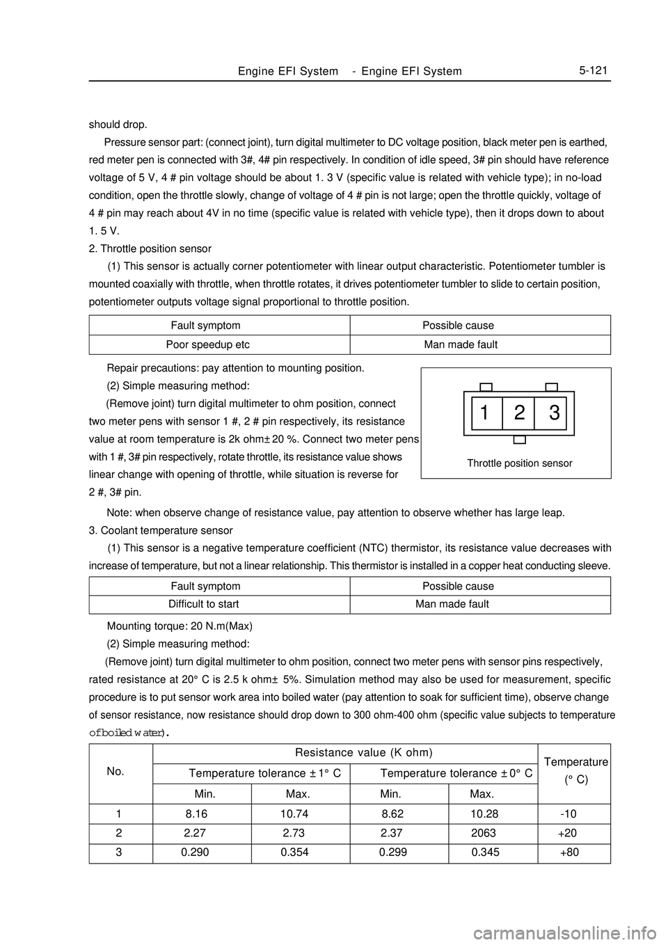
Poor speedup etc Man made fault1 2 3Throttle position sensorFault symptom Possible cause
Difficult to start Man made fault Repair precautions: pay attention to mounting position.
(2) Simple measuring method:
(Remove joint) turn digital multimeter to ohm position, connect
two meter pens with sensor 1 #, 2 # pin respectively, its resistance
value at room temperature is 2k ohm±20 %. Connect two meter pens
with 1 #, 3# pin respectively, rotate throttle, its resistance value shows
linear change with opening of throttle, while situation is reverse for
2 #, 3# pin.
Note: when observe change of resistance value, pay attention to observe whether has large leap.
3. Coolant temperature sensor
(1) This sensor is a negative temperature coefficient (NTC) thermistor, its resistance value decreases with
increase of temperature, but not a linear relationship. This thermistor is installed in a copper heat conducting sleeve.Engine EFI System-Engine EFI System5-121should drop.
Pressure sensor part: (connect joint), turn digital multimeter to DC voltage position, black meter pen is earthed,
red meter pen is connected with 3#, 4# pin respectively. In condition of idle speed, 3# pin should have reference
voltage of 5 V, 4 # pin voltage should be about 1. 3 V (specific value is related with vehicle type); in no-load
condition, open the throttle slowly, change of voltage of 4 # pin is not large; open the throttle quickly, voltage of
4 # pin may reach about 4V in no time (specific value is related with vehicle type), then it drops down to about
1. 5 V.
2. Throttle position sensor
(1) This sensor is actually corner potentiometer with linear output characteristic. Potentiometer tumbler is
mounted coaxially with throttle, when throttle rotates, it drives potentiometer tumbler to slide to certain position,
potentiometer outputs voltage signal proportional to throttle position. Mounting torque: 20 N.m(Max)
(2) Simple measuring method:
(Remove joint) turn digital multimeter to ohm position, connect two meter pens with sensor pins respectively,rated resistance at 20°C is 2.5 k ohm± 5%. Simulation method may also be used for measurement, specificprocedure is to put sensor work area into boiled water (pay attention to soak for sufficient time), observe changeof sensor resistance, now resistance should drop down to 300 ohm-400 ohm (specific value subjects to temperatureof boiled water).
Resistance value (K ohm)
No.Temperature
(°C) Temperature tolerance ±1°C Temperature tolerance ±0°C
Min. Max. Min. Max.
1 8.16 10.74 8.62 10.28 -10
2 2.27 2.73 2.37 2063 +20
3 0.290 0.354 0.299 0.345 +80
Page 309 of 416
4. Knocking sensor
(1) Knocking sensor is a vibration acceleration sensor. Mounted on engine cylinder body. Sensing element of
the sensor is a piezocrystal. Vibration of engine cylinder body is transferred to piezocrystal via mass block in the
sensor. Since pressure generated by vibration of mass block is applied to piezocrystal, it generates voltage on two
polar planes and turns vibration signal into voltage signal for output.5-122Symptom
Poor accelerationPossible cause
Various liquids, such as engine oil, cooling fluid, brake fluid, water etc
contact the sensor for a long time, which cause corrosion to the sensor. Mounting torque: 20 ± 5 N.M
Repair precautions: sensor must be fitted closely to cylinder body with its metal surface, any type of washer
is not permitted for installation. For wiring of sensor signal cables, note that do not let resonance occur to signal
cables, otherwise they might be broken. Energizing of high voltage between sensor 1 # and 2 # pins must be
avoided, otherwise piezoelectric element might be damaged.
(2) Simple measuring method:
(Remove joint) turn digital multimeter to ohm position, connect two meter pens with sensor 1 #, 2 # pin
respectively, its resistance value at room temperature should exceed 1M ohm. Turn digital multimeter to millivolt
position, use a hand hammer to tap near knocking sensor, now voltage signal output should be available.
5. Oxygen sensor
(1) Its sensing element is a ceramic tube, outside is open to exhaust, inside is open to atmosphere. When
temperature of sensing ceramic tube reaches 350°C, it will have the characteristic of solid state electrolyte. Just
utilizing this characteristic, it converts concentration difference of oxygen into electric potential difference, thus
forms electrical signal output. If mixed gas is a bit concentrated, inside and outside oxyanion concentration
difference of ceramic tube is high, electric potential difference is a bit high.
A large number of oxyanions move from inside to outside, output voltage is high (approximate 900mV); if
mixed gas is a bit thin, inside and outside oxyanion concentration difference of ceramic tube is low, electric
potential difference is low, only a small quantity of oxyanions move from inside to outside, output voltage is low
(approximate 100mV).
Possible cause
1. humid water vapor ingresses inside of sensor, temperature
changes rapidly, probe is broken.
2. oxygen sensor "is poisoned". (Pb, S, Br, Si) Symptom
Poor idle speed, poor speedup, tail gas
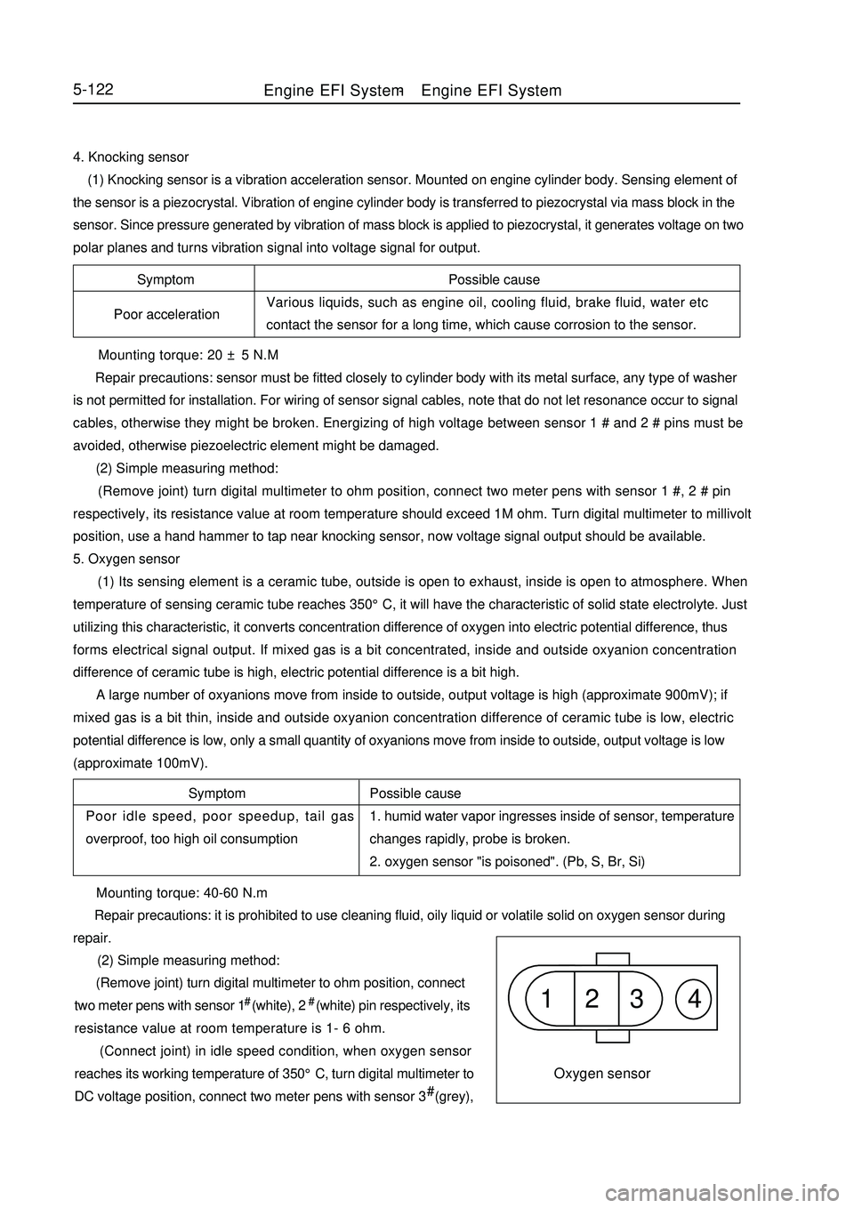
overproof, too high oil consumption1 2 3 4Oxygen sensor Mounting torque: 40-60 N.m
Repair precautions: it is prohibited to use cleaning fluid, oily liquid or volatile solid on oxygen sensor during
repair.
(2) Simple measuring method:
(Remove joint) turn digital multimeter to ohm position, connect
two meter pens with sensor 1# (white), 2# (white) pin respectively, its
resistance value at room temperature is 1- 6 ohm.
(Connect joint) in idle speed condition, when oxygen sensor
reaches its working temperature of 350°C, turn digital multimeter to
DC voltage position, connect two meter pens with sensor 3# (grey),Engine EFI System-Engine EFI System
Page 310 of 416

Symptom Possible cause
Fail to start Man made faultSpeed sensor1 2 3Fault symptom Common cause
Dischrge overproof, increased oil consumption Man made fault5-1234#(black) pin respectively, now voltage should fluctuate quickly between 0. 1-0. 9V.
6. Speed sensor
(1) Use with oscillator. Oscillator is a fluted disc, originally has 60 teeth, but two teeth are absent. Oscillator
is mounted on crankshaft, and rotates with the crankshaft. When tooth tip passes by sensor end closely, the
oscillator which is made of ferromagnetic material cuts magnetic line of permanent magnet in the sensor, and
generates induced voltage in coil, which is output as rotating speed signal. Mounting torque: 8 ± 2 N.m
Repair precautions: use pressing in instead of hammering method for installation during repair.
(2) Simple measuring method:
(Remove joint) turn digital multimeter to ohm position, connect
two meter pens with sensor 2#, 3# pins respectively, rated resistance
at 20°C is 770-950 ohm.
(Connect joint) turn digital multimeter to AC voltage position,
connect two meter pens with sensor 2 #, 3# pins respectively, start up
engine, now voltage output should be available.
Suggestion: use oscillograph for vehicle use to check.
7. Phase sensor
(1) This sensor consists of a hall sensor and a rotor made of steel plate. Fix hall sensor, mount rotor on camshaft.
Rotor is a 180( range cylindrical face steel blade. When the blade covers hall sensor, high Level signal is output;
otherwise low level signal is output. This differentiates two different upper dead points. Repair precautions: avoid removing end cover as far as possible during repair, so as to avoid ingress of foreign
matter, which might result in abnormal damage of magnetic gate.
(2) Simple measuring method:
(Connect joint) turn on ignition switch but not start up engine, turn digital multimeter to DC voltage position,
connect two meter pens with sensor red, black conductors respectively, ensure reference voltage of 5V is available.
Start up engine, voltage output between green and black conductors should be available.
Suggestion: use oscillograph for vehicle use to check.
8. Idle speed regulator
(1) Idle speed regulator consists of a step motor and a sealing plug on its shaft, sealing plug may generate radial
displacement driven by step motor shaft, position of sealing plug determines extent of opening of by-pass airway,
so as to adjust the size of by-pass air quantity. Position of sealing plug is controlled by ECU output.Fault symptom
Too high idle speed, flameout at idle speedPossible cause
Since interior contamination is severe, regulating element
is blocked and leads to malfunction.
Repair precautions: dust and sand grain will result in damage of idle speed regulator. Intake air should be
filtered by dry air cleaner before entering idle speed regulator, filtration efficiency should exceed 99 %. ToEngine EFI System-Engine EFI System