HONDA INTEGRA 1994 4.G Workshop Manual
Manufacturer: HONDA, Model Year: 1994, Model line: INTEGRA, Model: HONDA INTEGRA 1994 4.GPages: 1413, PDF Size: 37.94 MB
Page 941 of 1413
Rear Wndow
Installation (cont'dl
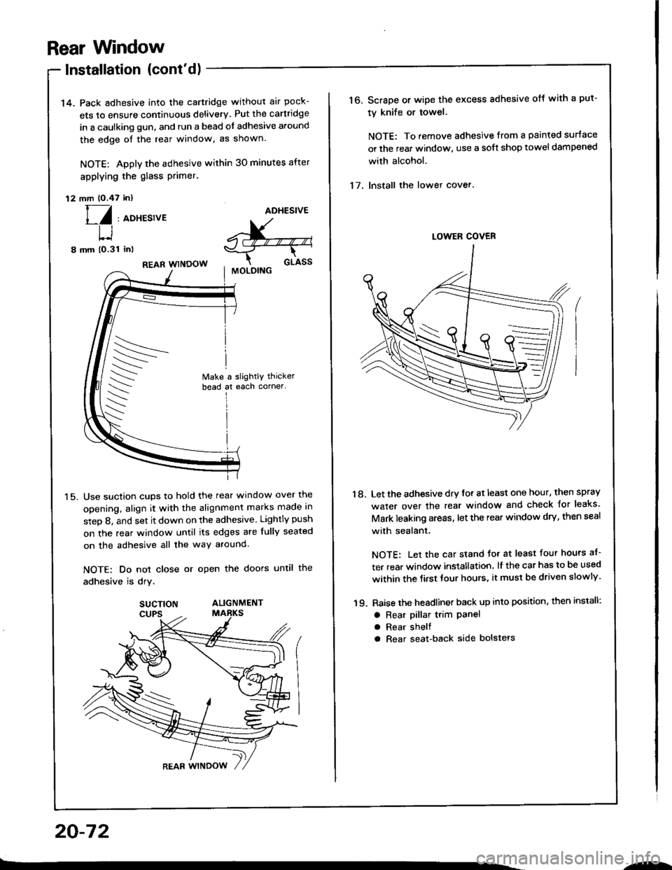
14. Pack adhesive into the cartridge without air pock-
ets to ensure continuous delivery. Put the cartridge
in a caulking gun, and run a bead of adhesive around
the edge oI the rear window, as shown.
NOTE: Apply the adhesive within 30 minutes after
applying the glass Primer.
12 mm (O.47 inl
[/ , aoxesrveADHESIVE
^X-"--"-,s-_T--r-
cr-rssI MOLOING
t-l
8 mm (o,31 inl
15.
REAR WINDOW
Use suction cups to hold the rear window over the
opening, align it with the alignment marks made in
step 8, and set it down on the adhesive Lightly push
on the rear window until its edges are fully seated
on the adhesive all the way around.
NOTE: Do not close or open the doors until the
adhesive is drv.
SUCTION ALIGNMENT
20-72
.-
16. Scrape or wipe the excess adhesive off with a put-
ty knife or towel.
NOTE: To remove adhesive from a painted surtace
or the rear window, use a soft shop towel dampened
with alcohol.
17. Install the lower cover.
'18. Let the adhesive dry for at least one hour, then spray
water over the rear window and check Jor leaks'
Mark leaking areas, let the rear window dry, then seal
with sealant.
NOTE: Let the car stand Jo. at least four hours af-
ter rear window installation, lf the car has to be used
within the tirst tour hours, it must be driven slowly'
19. Raise the headliner back up into position, then install:
a Rear pillar t.im Panela Rear shelf
a Rear seat-back side bolstels
Page 942 of 1413
Ouarter Glass
Replacement
a W€ar glov€s to romove and installthe quartol glass.a Use seat covers to avoid damaging any surfaces.
NOTE: Replace the quarter glass with new one whenremoving it.
1. To remove the quarter glass, first remove the quarter
trim (see page 20 93).
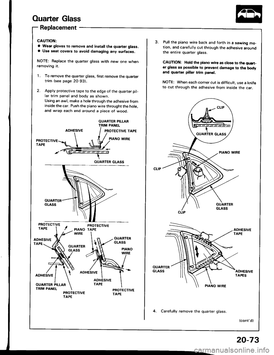
2. Apply protective tape to the edge of the quarter pil-
lar trim panel and body as shown.
Using an awl. make a hole through the adhesive frominside the car. Push the piano wire throught the hole,and wrap each end around a piece of wood.
OUARTER PILI.ARTRIM PANEL
AOHESIVEPROTECTIVE TAPE
PIAI{O wlREPROTECTIVETAPE
PROTECTIVETAPE
ADHESIVETAPE
ADHESIVEADHESIVE
OUARTER PILLARTRIM PANELPROTECTIVETAPE
OUARTER GLASS
OUARTER GLASS
CLIP
3. Pull the piano wire back and forth in a sawing mo-tion, and carefully cut through the adhesive aroundthe entire quarter glass.
CAUTION: Hold th€ tiano wire as closo to the qurt-er glass as possible to prevent damage to th6 bodyand quarter pillar trim panol.
NOTE: When each corner cut is difficult. use a knifeto cut through the adhesive from inside the car.
4. Carefully remove the quarter glass.
20-73
Page 943 of 1413
Ouarter Glass
Replacement (cont'd)
Scrape the old adhesive smooth with a knife. to a
thickness of about 2 mm (O.08 in) on the bonding
surface around the entire quaner glass opening
flange.
NOTE:
a Do not scrape down to the painted surface of the
body: damaged paint will interfere with proper
bonding.
a Mask oft surrounding surfaces before applying
orimer.
Clean the body bonding surface with a sponge damp-
ened in alcohol.
NOTE: Atter cleaning, keep oil, grease and water
from getting on the surtace.
Clean the new quarter glass surface with alcohol
where adhesive is to be aDDlied.
NOTE: Make sure the bonding surface is kept tree
of water, oil and grease.
CAUTION: Avoid setting th€ quartsr glass on its
edgas; small chips may later d€velop into cracks.
b-
CLIP
Clean the shadowed area allthe way around.CLIP
srDE sPAcER I
nrolonc i
\/ i
IfR-.s I-l i
_c$$l
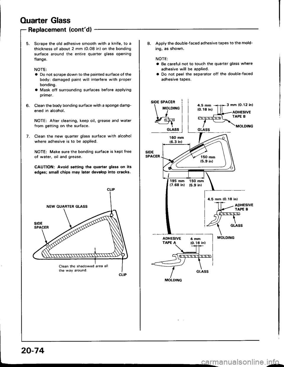
8. Apply the double-faced adhesive tapes to the mold-
ing, as shown,
NOTE:
o Be careJul not to touch the quarter glass where
adhesive will be applied.
a Do not peel the separator off the double-taced
adhesive taPes.
3 mm (0.12 inl
ADHESIVETAPE 8
MOLDING
195 mm 150 mm(?.68 in) 15.9 inl
MOLDING
4.5 mm 1O.18 inl
ADHESIVE
MOLDING
--
Page 944 of 1413
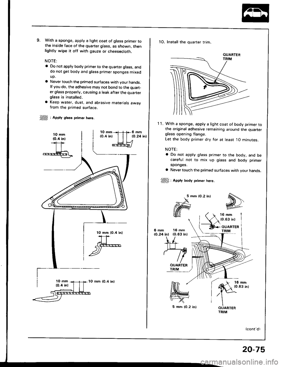
9. With a sponge. apply a light coat of glass primer tothe inside face ot the quarter glass, as shown, thenlightly wipe it ott with gauze or cheesecloth.
NOTE:
a Do not apply body primer to the quaner glass, anddo not get body and glass primer sponges mixedup.
a Never touch the primed surlaces with your hands.lf you do, the adhesive may not bond to the quan-
er glass properly, causing a leak after the quarterglass is installed.
a Keep water, dust. and abrasive materials awavfrom the primed surface.
V/// , AooV glass primer h6re-
10 mm lO.4 inl
10 mm lO,4 inl
1O. Install the quarter trim.
1 1. With a sponge. apply a light coat of body primer tothe original adhesive remaining around the quarte.glass opening flange.
Let the body primer dry lor at least 1O minutes.
NOTE:
a Do not apply glass primer to the body, and becareful no1 to mix up glass and body prime.
sponges.
a Never touch the primed surfaces with your hands.
'////7, , aepty body p.imer here.
lO.2 inl5mm
ffi
16 mm{0.63 in}
'16 mm(0.63 inl
6mm10.24 in)
OUARTERTRIM
(cont'd )
OUARTER
5 mrr| 10.2 inl
20-75
Page 945 of 1413
Ouarter Glass
SIOE SPACER
ADHESIVETAPE A
Replacement (cont'd)
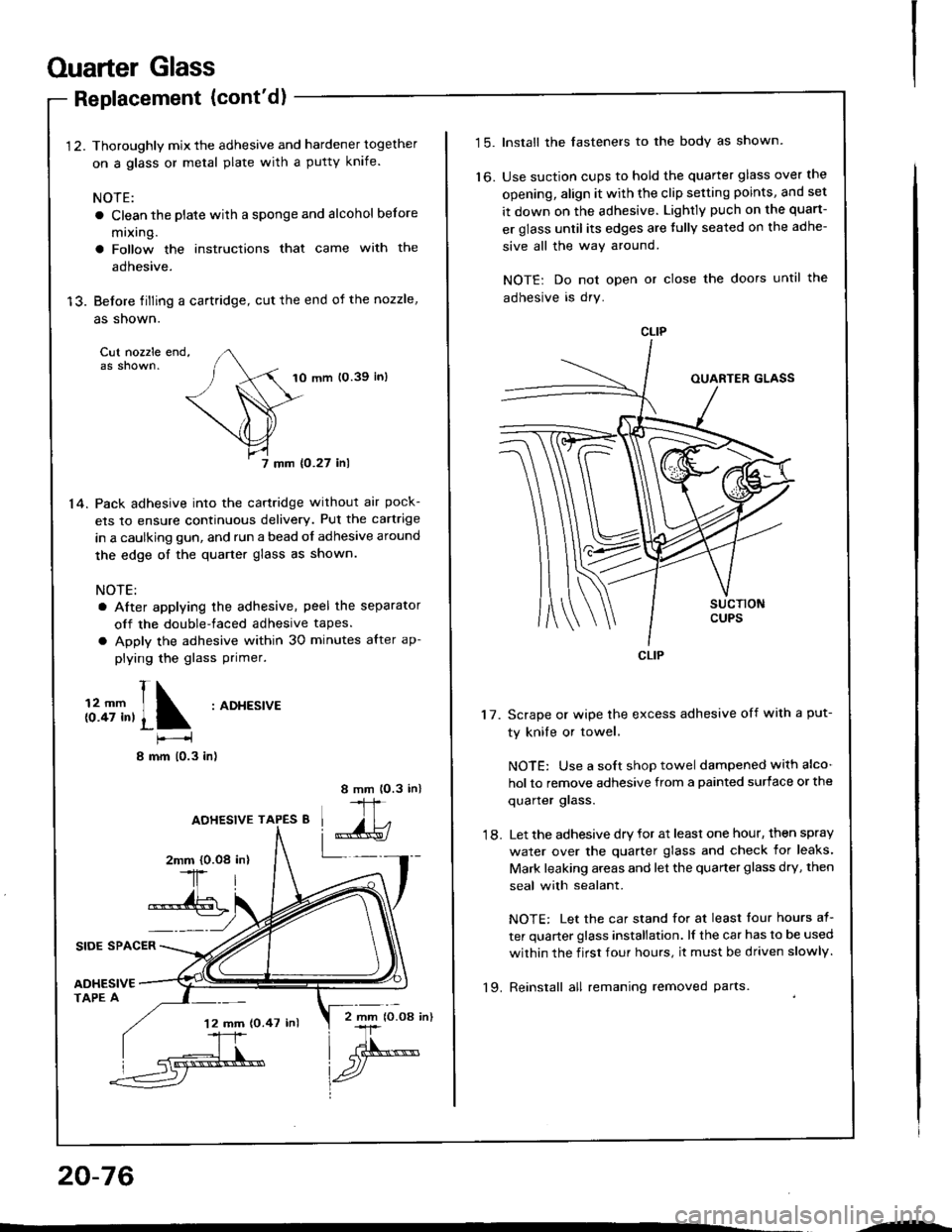
1 2. Thoroughly mix the adhesive and hardener together
on a glass or metal plate with a putty knife.
NOTE:
a Clean the plate with a sponge and alcohol before
mixing.
a Follow the instructions that came with the
adhesive.
13. Before tilling a cartridge, cut the end of the nozzle,
as shown.
Cut nozzle end,as shown.10 mm 10.39 in)
7 mm {0.27 inl
14. Pack adhesive into the cartridge without air pock-
ets to ensure continuous delivery. Put the cartrige
in a caulking gun, and run a bead of adhesive around
the edge of the quarter glass as shown.
NOTE:
a After applying the adhesive, peel the separator
off the double-faced adhesive tapes.
a Apply the adhesive within 30 minutes after ap-
plying the glass Primer.
t1;T,,1 :ADt'�Es'�vE
I mm 10.3 in)
8 mm lO.3 in)
IJ,
L_-_2mm {0.08-1r
*-{6
AOHESIVE TAPES 8
20-76
'12 mm (0.47 inl2 mm lO.O8 in)
--
t5.Install the fasteners to the body as shown.
Use suction cups to hold the quarter glass over the
opening, align it with the clip setting points, and set
it down on the adhesive. Lightly puch on the quart-
er glass until its edges are tully seated on the adhe-
sive all the way around.
NOTE: Do not open or close the doors until the
adhesive is dry.
to.
17. Scrape or wipe the excess adhesive off with a put-
ty knile or towel,
NOTE: Use a soft shop towel dampened with alco-
hol to remove adhesive from a painted surface or the
quarler glass.
18. Let the adhesive dry for at least one hour, then spray
water over the quarter glass and check for leaks'
Mark leaking areas and let the quarter glass dry, then
seal with sealant.
NOTE: Let the car stand for at least tour hours at-
ter quarter glass installation. lf the car has to be used
within the f irst four hours, it must be driven slowly.
'19. Reinstall all remaning removed parts.
Page 946 of 1413
Moonroof
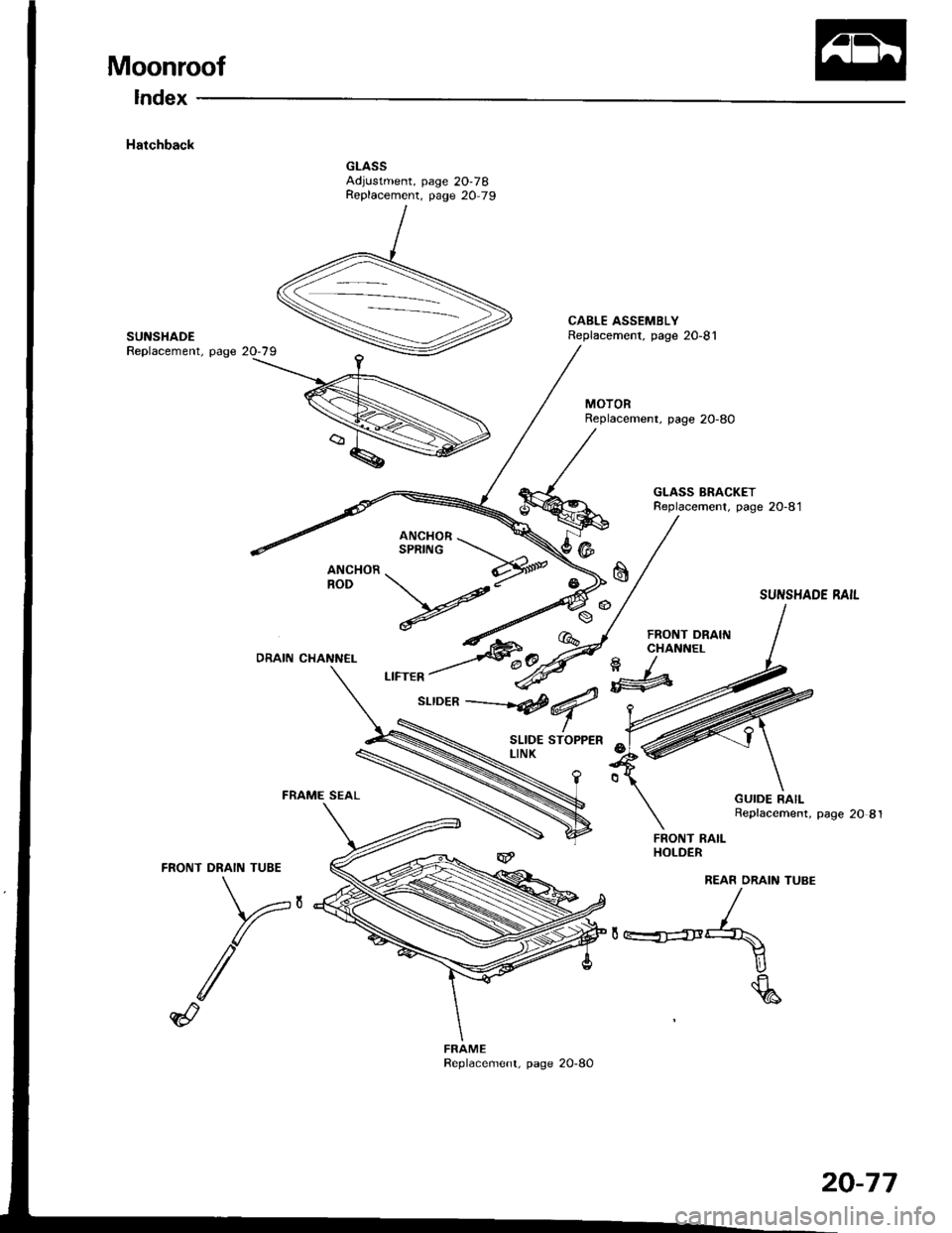
Index
Hatchback
CABLE ASSEMBLYReplacement, page 2O-81SUNSHADEReplacement, page 20-79
MOTORReplacement, page 20-80
GLASS BRACKETReplacement, page 20-81
DRAIN CHANN€L
FRONT DRAII{CHANNEL
a/'#
-4
SUI{SHADE RAIL
Replacement, page 20 8l
FRAME SEAL
FRONT RAILHOLDER
REAR ORAIN TUBE
,**4
U
\a
GUIDE RAIL
FRAME
20-77
Page 947 of 1413
Moonroof
Troubleshooting
SymptomProbable Cause
Water leaks1
4
Clogged drain tube.
Gap between glass weatherstrip and roof panel.
Defective or improperly installed glass weatherstrip.
GaD between drain seal and roof panel.
Wind noise1. Excessive clearance between glass weatherstrip and roof panel.
Motor noise1. Loose motor.
2. Worn gear or bearing.
3. Cable assembly deformed.
Glass does not move, but motor
turns
1. Clutch out of adjustment.
2. Foreign matter stuck between guide rail and slider,
3. Inner cable loose.
4. Cable assembly not attached properly.
Glass does not move and motor
does not turn (glass can be moved
with moonroof wrench)
1. Blown fuse.
2. Faulty switch.
3. Battery run down.
4. Defective motor.
5. Faulty realy.
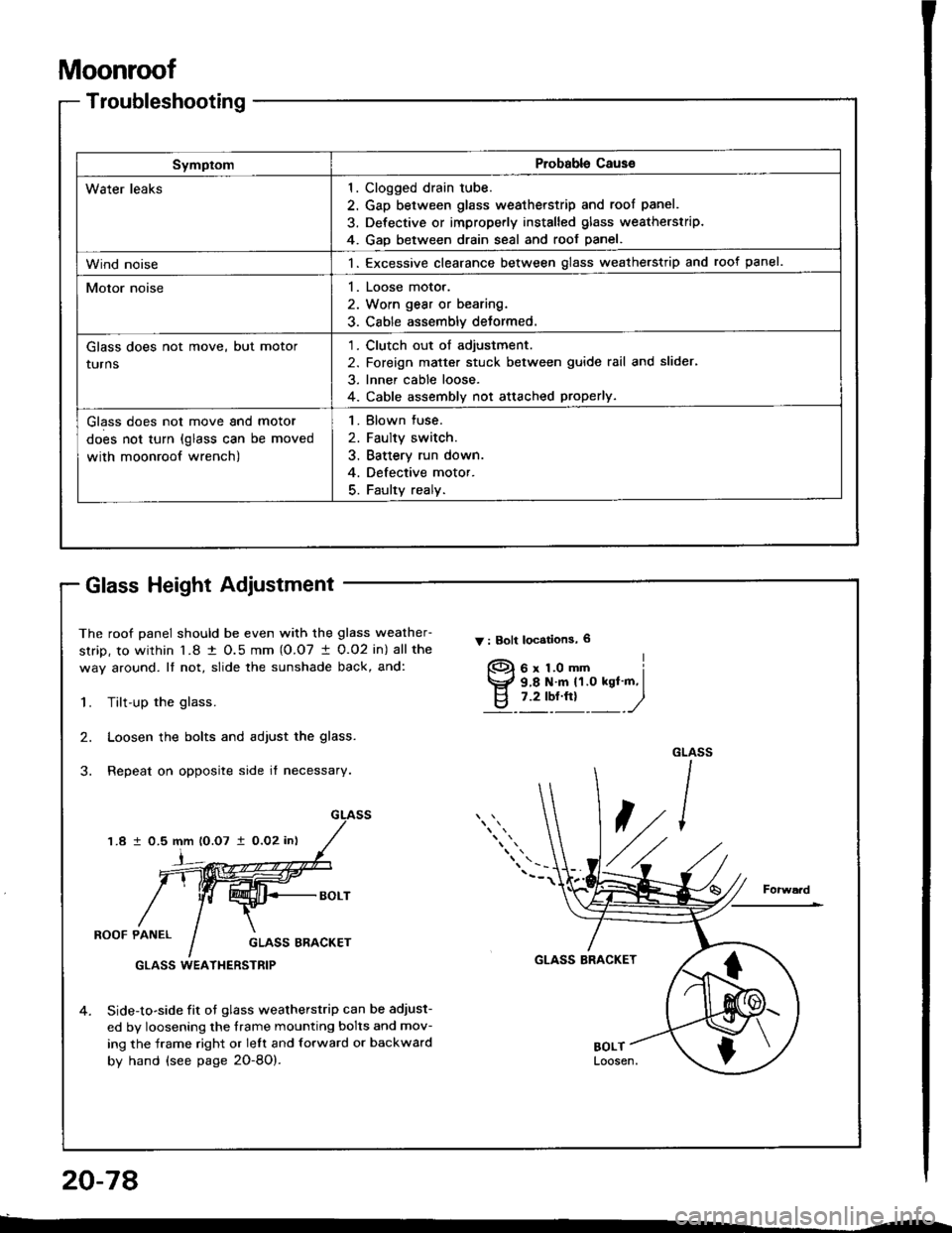
The roof panel should be even with the glass weather-
strip, to within l�8 t O.5 mm (O.O7 I 0.O2 in) all the
way around. It not, slide the sunshade back, and:
Y : Bolt locstions, 6
1.Tilt-up the glass.
Loosen the bolts and adjust the glass.
Repeat on opposite side it necessary.
2.
1.8 1 0.5 mm lO.O7 i0,O2 in)
i
ROOF PANELGLASS ERACKET
GLASS BRACKET
4.Side-to-side fit ot glass weatherstrip can be adjust-
ed by loosening the frame mounting bolts and mov-
ing the frame right or lelt and forward or backward
by hand (see page 2O-8O).
GLASS WEATI{ERSTRIP
f)
Glass Height Adiustment
20-78
Page 948 of 1413
Rear Edge Closing Adjustment
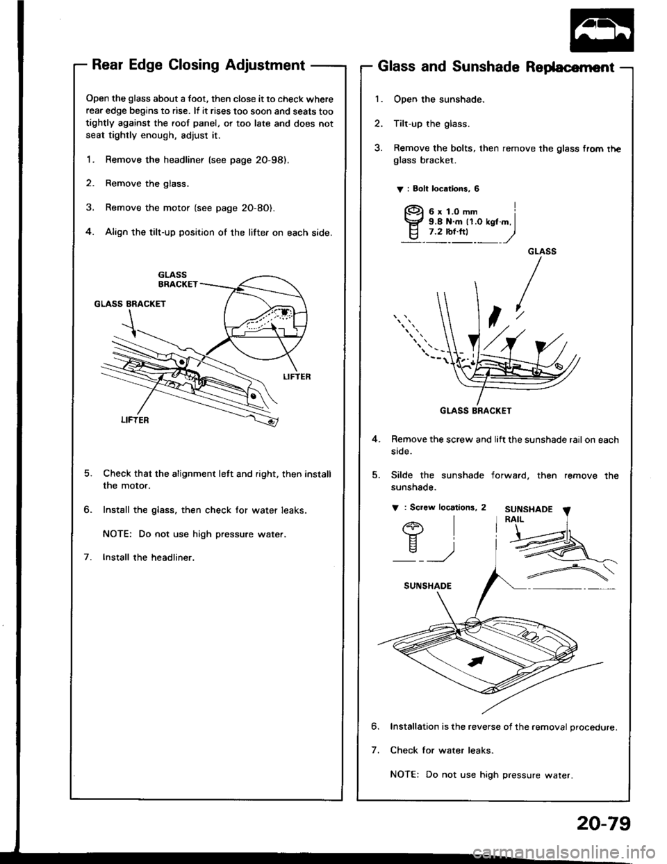
Open the glass about a foot, then close it to check where
rear edge begins to rise. lf it rises too soon and seats too
tightly against the roof panel, or too late and does not
seat tightly enough, adjust it.
1. Remove the headliner (see psge 20-98).
2. Remove the glass.
3. Remove the motor {see page 2O-8O).
4. Align the tilt-up position of the lifter on each side.
Check that the alignment left and right. then install
the motor.
Install the glass, then check for water leaks.
NOTE: Do not use high pressure wate..
lnstall the headliner.
Glass and Sunshade Redacernent
1. Open the sunshade.
2. Tilt-up the glass.
3. Remove the bolts, then remove the glass from rheglass bracket.
V : 8oh locations, 6
4. Remove the screw and lift the sunshade rail on each
side.
5. Silde the sunshade
sunshade.
V : Scraw locations, 2
forwa.d, then remove the
SUNSI{ADE
l-tII
)
6
7
Installation is the reverse of the removal procedure.
Check for water leaks.
NOTE: Do not use high pressure water.
GLASS BRACKET
20-79
Page 949 of 1413
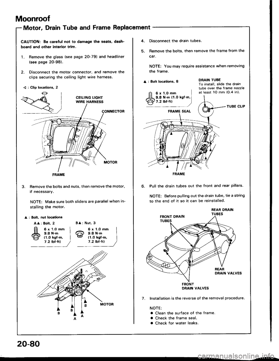
Moonroof
Motor, Drain Tube and Frame Replacement
CAUTION: B€ caretul not to damag€ lhe seats, dash-
board and other interior trim.
1. Remove the glass (see page 2O-79) and headliner
(see page 20-98).
2. Disconnect the motor connector, and remove the
clips securing the ceiling light wire harness.
3. Remove the bolts and nuts, then remove the motor,
if necessarv,
NOTE: Make sure both sliders are parallel when in-
stalling the motor.
: 8olt, nut locationg
A
: Bolt, 2
6x1.Omm I9.8 N.m ILd tt.o kgf.-, I,.?- ", _,/
< : CliD locations. 2
CEILIING LIGHT
FRAME
B : Nut, 3
20-80
4.Disconnect the drain tubes.
Remove the bolts, then remove the trame from the
car.
NOTE: You may require assistance when removing
the frame.
: Eolt locations, I
6 x 1.0 mm
DRAIN TUBETo install, slide the draintube over the ftame nozzleat least 10 mm {O.4 in}.
6.
TUBE CI-IP
Pull the drain tubes out the front and rear pillars.
NOTE; Betore pulling out the drain tube, tie a string
to the end of it so it can be reinstalled.
Installation is the reverse ol the removal procedure.
NOTE:
a Clean the surtace of the frame.
a Check the trame seal.
a Check for water leaks.
7.
9.8 N.m (1.0 kgt m,7.2 rbr.ttl )
FRAME
FRONT
Page 950 of 1413
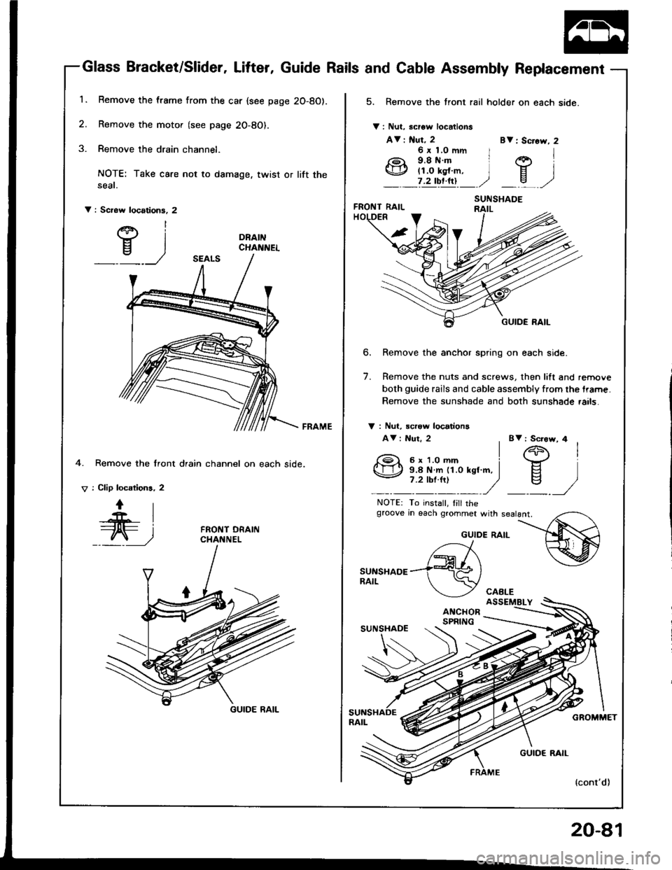
1.Remove the frame from the car {see page 2O-8O).
Remove the motor (see page 2O-8O).
Remove the drain channel.
NOTE: Take care not to damage, twist or lift theseat.
V : Screw locations, 2
DRAINCHAI{NEL
4. Remove the front drain
V : Clip locations, 2
channel on each side.
GUIDE RAIL
20-81
Glass Bracket/Slider, Lifter, Guide Rails and Cable Assembly Replacement
5. Remove the front rail holder on each side.
V : Nut, scrow locations
AV : f{ut, 2
b.
7.
Remove the anchor spring on each side.
Remove the nuts and screws, then lift and remove
both guide rails and cable assembly from the trame.
Remove the sunshade and both sunshade rails.
BV: Screw,
BV : Sciow, 4
V : Nut, rcrow locations
AV : Nut. 2
NOTE: To instalt, Iill thegtoove rn each grommet with sealant,
GUIDE RAIL
SUNSHADE