HONDA INTEGRA 1998 4.G Workshop Manual
Manufacturer: HONDA, Model Year: 1998, Model line: INTEGRA, Model: HONDA INTEGRA 1998 4.GPages: 1681, PDF Size: 54.22 MB
Page 1131 of 1681
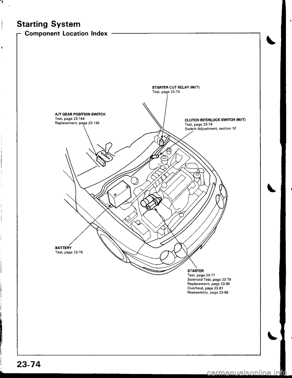
Starting System
Component LocationIndex
STARTER CUT RELAY (M/T)
Test, page 23-70
A/T GEAR POSITION SWITCHTest, page 23-144CLUTCH INTERLOCK SWITCH IM/T}Test, page 23-79Switch ,Adiustment, section 12
Replacement,
BATTERYTest, page 23 76
STARTERlest, page 23-77Solenoid Test, page 23 79Replacement, page 23'80Overha!1, page 23'81Reassembly, page 23'86
23-74
Page 1132 of 1681
![HONDA INTEGRA 1998 4.G Workshop Manual Circuit Diagram (M/Tl
tJ
STARTEBCUT RELAY
)/
ll-G2o1G401
rAa rtFz5- r3
) -rr
CLUTCHINTERLOCKSW]TCH
IGNITIONX SWITCH
!_*",.^-*-G-l
"T"
BTKWHT BLKWHT
llr - tr |
BLKFED 8LU/BLK
- BLK,BE I__-lrror.oo*
I HONDA INTEGRA 1998 4.G Workshop Manual Circuit Diagram (M/Tl
tJ
STARTEBCUT RELAY
)/
ll-G2o1G401
rAa rtFz5- r3
) -rr
CLUTCHINTERLOCKSW]TCH
IGNITIONX SWITCH
!_*",.^-*-G-l
"T"
BTKWHT BLKWHT
llr - tr |
BLKFED 8LU/BLK
- BLK,BE I__-lrror.oo*
I](/img/13/6069/w960_6069-1131.png)
Circuit Diagram (M/Tl
tJ
STARTEBCUT RELAY
)/
ll-G2o1G401
rAa rtFz5- r3
) -rr
CLUTCHINTERLOCKSW]TCH
IGNITIONX SWITCH
!_*",.^-*-G-l
"T"
BTKWHT BLKWHT
llr - tr |
BLKFED 8LU/BLK
- BLK,BE' I__-lrror.oo*
I I
+Yffii'"'Tf'o' | |
u"T-l
i,t^il'r** | |
=-T--. I
twt t
l$*Tl r
IA II
BLK
tY--lt I-|ffim-
|
rl
UNDEB HOOD FUSE/BELAY BOX
No 41 (100A) N0.42 (404)
Page 1133 of 1681
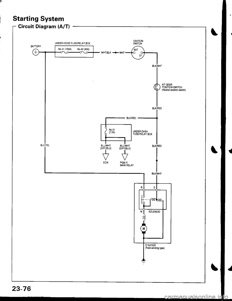
Starting System
Circuit Diagram (A/T)
IGNITIONSWITCH
/ BAT \--i.o
\jz IIBLKWHT
II
I
rl., - oro,( lI ) POStlOr\l swrTcHY+'/ {Nedtal Posilion swilch)
II
IELIVRED
WHT/BLK +WHT
::--JFUSBFELAYBox
ISLIffiED
I
IGBY/BLU]
J
ECM
STASTER(Field windiig ly!€)
UNDEF.HOOO FIJSE/RELAY BOX
BLI(YEL
N0.41 (100A) No.42 (40A)
23-76
Page 1134 of 1681
Ch6ck Starter Engag€mont;
1. Remove the No. 44 (15 A) fuse from the under-hood
fuse/relay box,
Press the clutch pedal all the way in (M/T), and turn
the ignition switch to "St8rt". The staner should
crank the engine,
NOTE: On cars equipped with manual transmission,
the engine will not crank unless the clutch pedal is
fully depressed.
lf the starter does not crank the engine, go to step 3.
Check the battery, battery positive cable, ground,
and the wire connections for looseness and cor-
rosion.
Test again. lf the stsner stilldoes not crank the en-
gine, go to step 4.
Bypass the ignition switch circuit as follows {make
sure the transmission is in neutral)
Unplug the connector (BLKMHT wire and solenoid
terminal) trom the staner. Then connect a jumper
wire from the batterv positive (+ ) terminal to the
solenoid terminal. The starter should crank the
engine.
a It the stsrter still does not crank the engine,
replace it and diagnose its internal problems,
a lf the starter cranks the engine. go to step 5.
(cont'd)
4.
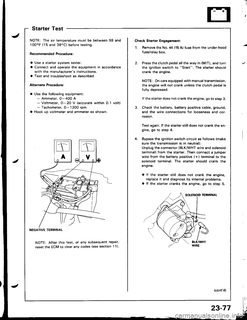
NOTE: The air temperature must be between 59 and
100oF {15 and 38'C) betore testing.
Recommended Procedure:
a Use a starter system tester.
a Connect and operate the equipment in accordance
with the manufacturer's instructions.
a Test and troubleshoot as described.
Alternate Procodure:
a Use the following equipment;- Ammeter, O-400 A- Voltmeter. O-20 V (accurate within O,1 volt)- Tachometer, O- 1 2OO rpm
a Hook up voltmeter and ammeter as shown.
NEGATIVE TERMINAL
NOTE: Atter this test, or any subsequent repalr,
reset the ECM to clear any codes (see section 1 1).
StartelTest
23-77
Page 1135 of 1681
Starting System
Starter Test (cont'dl
Check Cranking rpmr
Engine speed during cranking should be above 1OO rpm.
lJ speed is too low, check for:
a Loose batlery or starter terminals
a Excessively worn starter brushes
a Open circuit in commutator segments
a Dirty or damaged helical spline or drive gear
a Defective drive gear overrunning clutch
Check Starter Disengagement:
Press the clutch pedal all the way in (M/T), turn rhe igni
tion switch to "lll" and release to "11".
The starter drive gear should disengage from the flywheel
or torque converter ring gear when you release the key.
It the drive gear hangs up on the flywheel or torque con-
verter ring gear, check for:
a Solenoid plunger and switch mallunction
a Dirty drive gear assembly or damaged overrunning
clutch
5. Check for an open in the BLK/WHT wire circuit be
tween the starter and ignition switch, and con-
necrors,
6. Check the ignition switch (see page 23-71).
7. On cars with automatic transmission, check the A/Tgear position switch (neutral position switch) and
connector. On cars with manualtransmission, check
the starter cut relay, clutch interlock switch, and
connectors.
NOTE: Check the No. 42 (40 A) fuse in the under,hoodfuse/relay box for the starter cut relay.
Check Jor Wear and Damage:
The starter should crank the engine smoothly and stead,ily. lf the starter engages, but cranks the engine errati
cally, remove it. Inspect the starter, drive gear, andllywheel or torque converter ring gear lor damage.
a Check the drive gear overrunning clutch for binding
or slipping when the armature is rotated with the drivegear held. Replace the gears i{ damaged.
Check CJanking Voltage and Current Draw:
Cranking voltage should be no less than 8.O volts.
Current draw should be no more than * amperes.* 1.2 kW: 27O A
1 .4 kW: 360 A
It cranking voltage is too low, or current draw too high,check for:
a Dead or low charged batterya Open circuit in starter armature commutator segmentsa Starter armalure dragging
a Shorted armature windinga Excessive drag in engine
Page 1136 of 1681
![HONDA INTEGRA 1998 4.G Workshop Manual 1.Remove the dashboard lower cover and knee bolster(see page 23-71],, then disconnect the 2P connector
from the switch.
Check for continuity between the terminals accord-
ing to the table.
2.
3.ll nec HONDA INTEGRA 1998 4.G Workshop Manual 1.Remove the dashboard lower cover and knee bolster(see page 23-71],, then disconnect the 2P connector
from the switch.
Check for continuity between the terminals accord-
ing to the table.
2.
3.ll nec](/img/13/6069/w960_6069-1135.png)
1.Remove the dashboard lower cover and knee bolster(see page 23-71],, then disconnect the 2P connector
from the switch.
Check for continuity between the terminals accord-
ing to the table.
2.
3.ll necessary, replace the switch or adiustthe switch
position (see section 12).
Terminal
cr,t"hP;i
-_\B
RELEASED
PUSHEDoo
Clutch lnterlock Switch TestStarter Solenoid Test
1. Check for continuity between the terminals accord-
ing to the table.
HOLD_ IN COIL
23-79
I
/
-
I
-a
Coil
Teminalt\4sHousing
HOLD INO-o
PULL-INo-o
PULL_ IN COIL
Page 1137 of 1681
Starting System
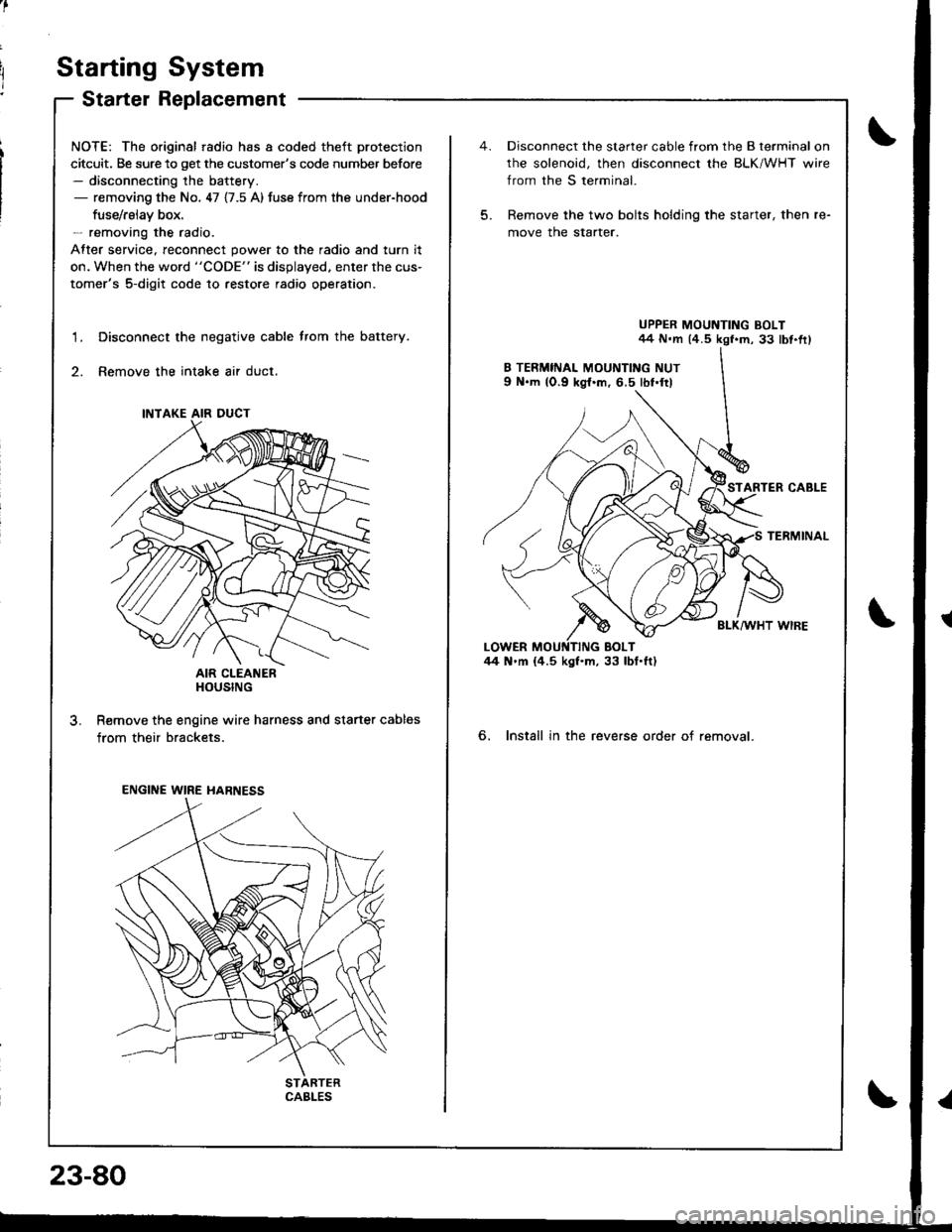
Starter Replacement
NOTE: The original radio has a coded theft protection
citcuit. Be sure to get the customer's code number before- disconnecting the battery.- removing the No. 47 {7.5 A) fuse from the under-hood
fuse/rslav box.- removing the radio.
After service, reconnect power to the radio and turn it
on. When the word "CODE" is displayed. enter the cus-
tomer's 5-digit code to restore radio operation.
Disconnect the negative cable trom the battery.
Remove the intake air duct.
AIR CLEANERHOUSING
R€move the engine wire harness and starter cables
from their brackets.
1.
3.
INTAKE AIR DUCT
ENGINE WIRE HARNESS
CABLES
23-80
5.
Disconnect the starter cable from the B terminal on
rhe solenoid, then disconnect the BLK/WHT wire
from the S terminal.
Remove the two bolts holding the starter, then re-
move the starter.
UPPER MOUNTING BOLT44 N.m (4.5 kgf.m, 33 lbt.fr)
STARTER CABLE
TERMINAL
BLK/WHT WIRE
6. Install in the reverse order of removal.
Page 1138 of 1681
I
,.
u
J
/
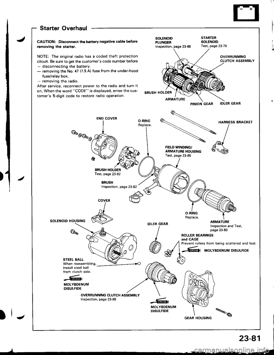
Starter Overhaul
CAUTION: Disconnect th€ banery negative cable botore
removing the starter.
NOTE: The original radio has a coded theft protection
citcuit. Be sure to get the customer's code number before- disconnecting the baftery.- removing the No. ,17 (7.5 A) fuse from the under-hood
fuse/relav box.- removing the radio.
After service, reconnect power to the radio and turn it
on. When the word "CODE" is displayed, enter the cus-
tomer's 5-digit code to restore radio operation.
BRUSH HOLDERTest, page 23-82
BRUSHInspectaon, page 23-82
SOLENOID HOUSING
STEEL BALL
install steel ballfrom clutch side.
-.''.!k.��rt{l{
MOLYBDENUMDISULFIDE
OVERRUNNING CLUTCH ASSEMBLYInspection, page 23-85
PINTON GEAB IDLER GEAR
\
HARNE'SBRA.KET
-\l
-
^,1FIELD WINDING/ 'A \
f:$i:y5J*"""
*\s
SOLENOIDPLUNGER
STARTEBSOLENOID
inspection,
BRUSH HOLDER
Test, page 23-79
OVERRUNNINGCLUTCH ASSEMBLY
ARMATURE
O-RING
COVER
I
6
%
-@t
MOLYBDENUMDISULFIDE
END COVER
GEAR HOUSING
Page 1139 of 1681
Staning System
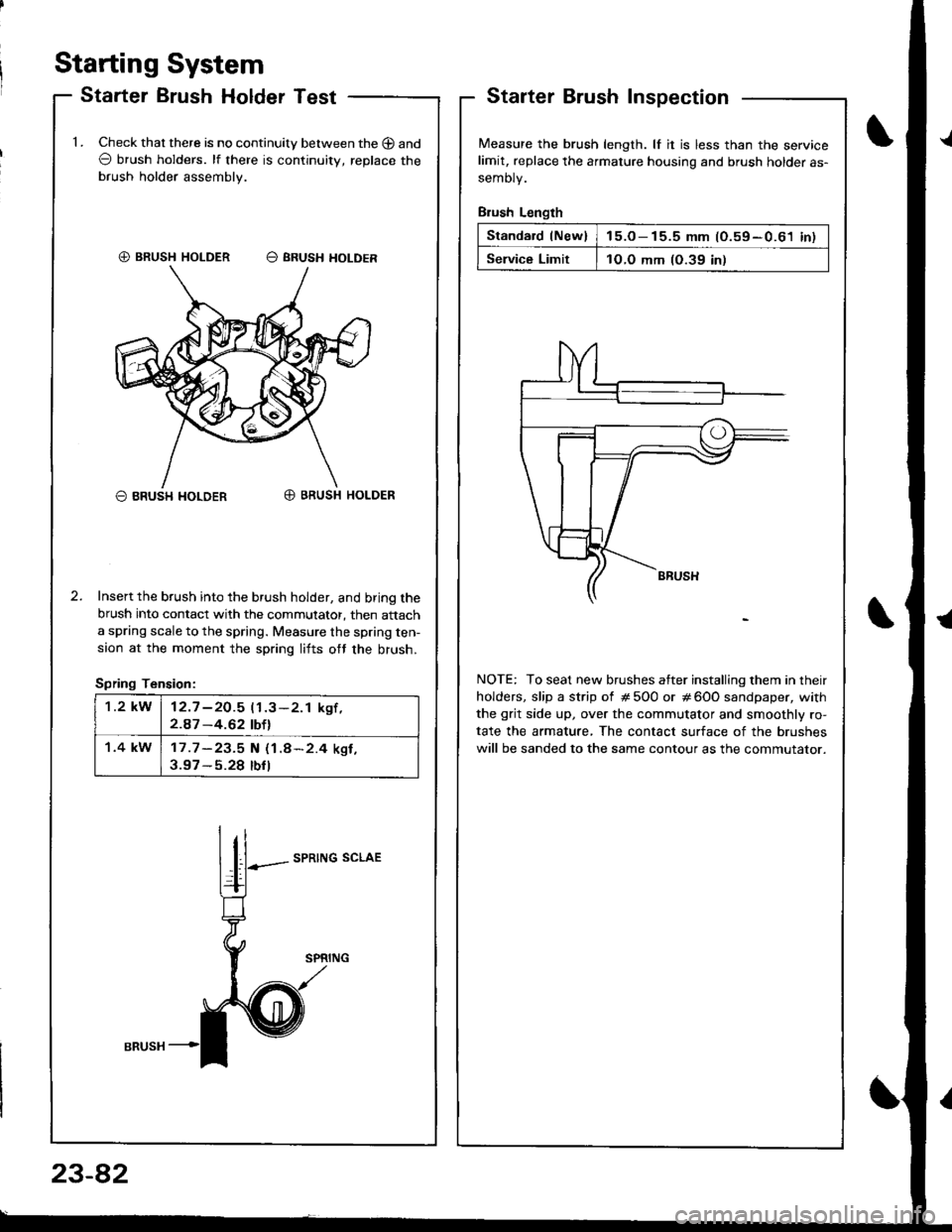
Starter Brush Holder TestStarterInspection
Measure the brush length. lf it is less than the servicelimit, replace the armature housing and brush holder as-
semoty.
Brush Length
Standard lNew)15.o- 15.5 mm (O.59-0.61 inl
Service Limit1O.O mm (O.39 in)
NOTE: To seat new brushes atter installing them in their
holders, slip a strip of # 5O0 or # 600 sandpaper, with
the grit side up, over the commutator and smoothly ro-
tate the armature, The contact surface of the brushes
will be sanded to the same contour as the commutator.
1.Check that there is no continuity between the O and
O brush holders. lf there is continuitv, replace the
brush holder assembly.
O BRUSH I{OLDERO BRUSH HOLDER
Insert the brush into the brush holder, and bring the
brush into contact with the commutator, then attach
a spring scale to the spring. Measure the spring ten-
saon at the moment the spring lifts ott the brush.
Spring Tension:
SPRING SCLAE
€) BRUSH HOLDER O SRUSH HOLDER
1.2 kW12.7 -2O.5 11.3-2.1 kgf ,2.A7 -4.62 tbtl
1.4 kW17 .7 -23.5 N (1.8*2.4 ksf ,3.97 - 5.28 tbfl
I
23-82
Page 1140 of 1681
J
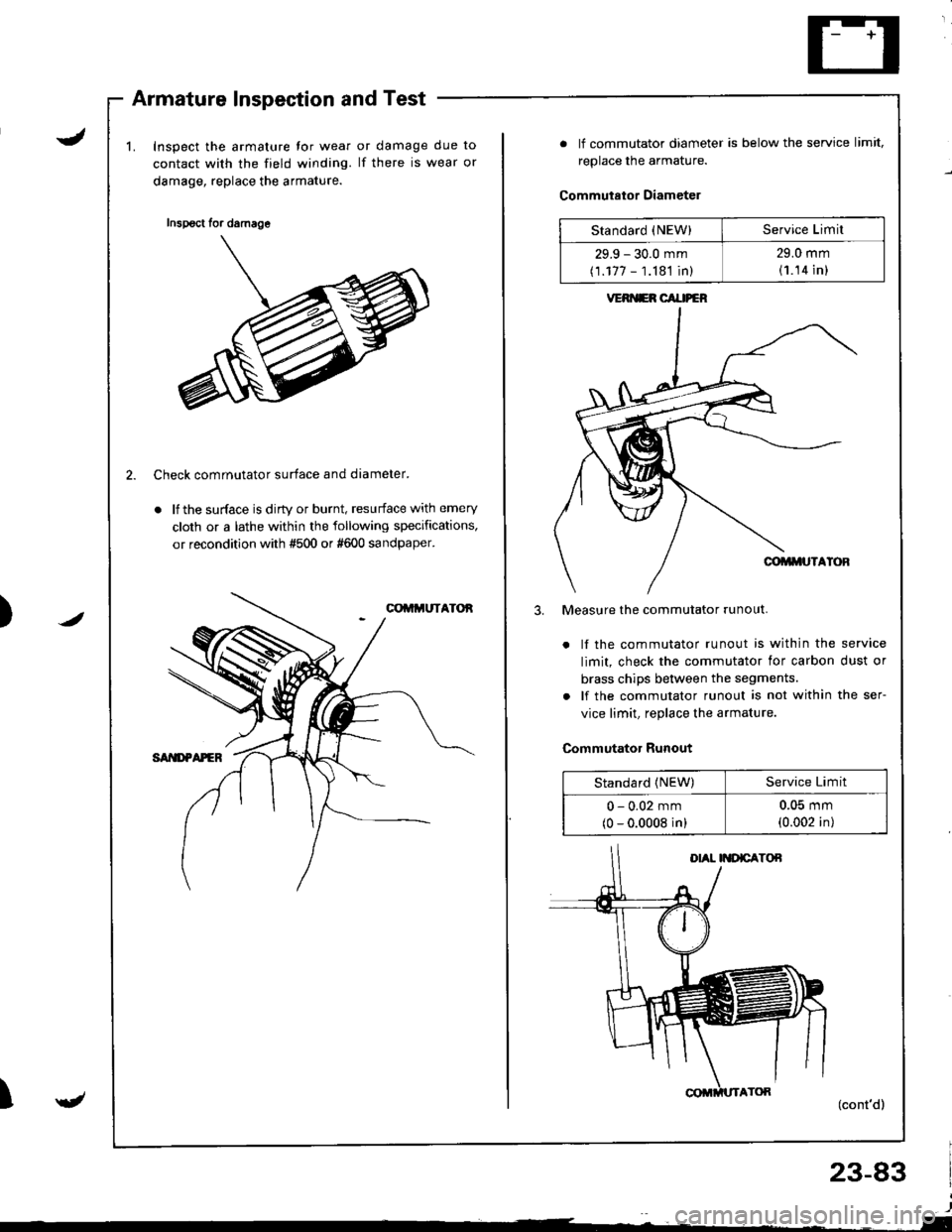
Armature Inspection and Test
Inspect the armature tor wear
contact with the field winding.
damage, replace the armature.
or damage due to
lf there is wear or
/)
2. Check comrnutator surface and diameter.
. lf the surface is dirty or burnt, resurface with emery
cloth or a lathe within the following specifications,
or recondition with #500 or #600 sandpaper.
gt
Inspsct for damage
. lf commutator diameter is below the service limit,
replace the armature.
Commutator Diameter
Measure the commutator runout.
. lf the commutator runout is within the service
limit, check the commutator lor carbon dust or
brass chips between the segments.
. lf the commutator runout is not within the ser-
vice limit, replace the armature.
Commutator Runout
(cont'd)
23-83
Standard (NEW)Service Limil
29.9 - 30.0 mm
(1.177 - 1.181 in)
29.0 mm
(1.14 in l
VERI{ER CAI|PEN
Standard (NEW)Service Limit
0 - 0.02 mm
(0 - 0.0008 in)
u-(J5 mm
(0.002 in)