HONDA INTEGRA 1998 4.G Workshop Manual
Manufacturer: HONDA, Model Year: 1998, Model line: INTEGRA, Model: HONDA INTEGRA 1998 4.GPages: 1681, PDF Size: 54.22 MB
Page 1151 of 1681
b-.
23-94
lgnition System
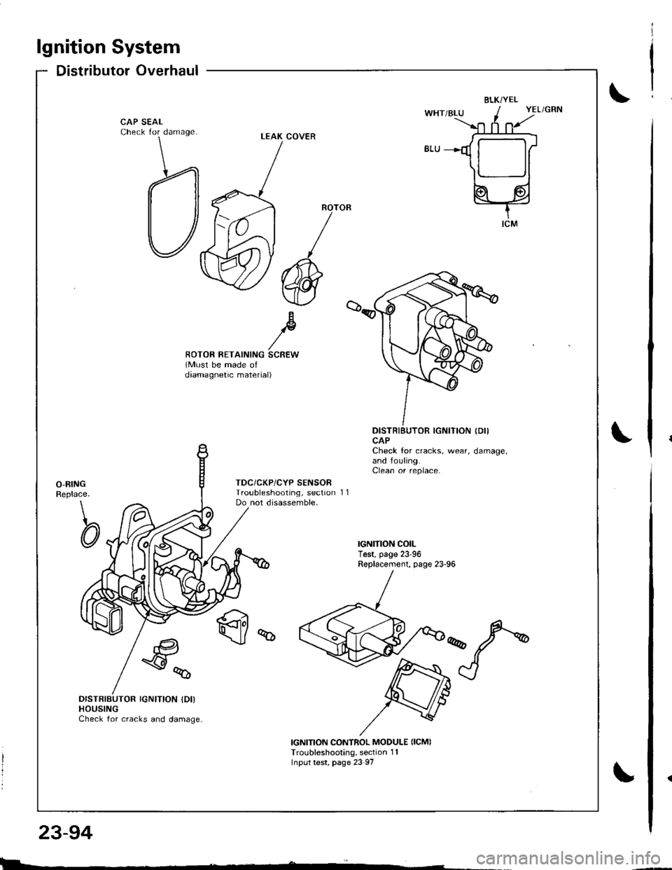
Distributor Overhaul
BLKi YEL
CAP SEALCheck for damage
Bp//ROTOR RETAINING SCREW(Must be made ofdaamagnetic material)
DISTRIBUTOR IGNITION (DII
CAPCheck for cracks, wear, damage,and fouling.Clean or replace.
O-RINGReplace.
\
CI
TDC/CKP/CYP SENSORTroubleshooting, sectionDo not disassemble,11
q
€a
\y%
DISTRIBUTOR IGNITION IDI)HOUSINGCheck for cracks and damage,
IGNITION CONTROL MODULE {ICMITroubleshooting, section 1 1Input test, page 23 97
LEAK COVER
l
I
I
|>l
Page 1152 of 1681
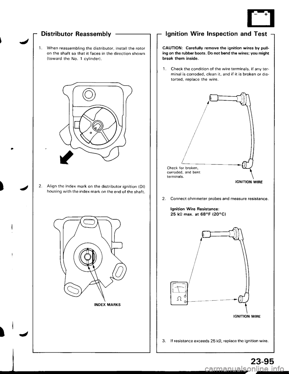
'1.When reassembling the distributor, install the rotor
on the shatt so that it faces an the direction shown(toward the No. 1 cvlinder).
2.Align the index mark on rhe distributor ignition (Dl)
housing with the index mark on the end of the shaft.
INDEX MARKS
Distributor Reassemblylgnition Wire Inspection and Test
J
J)
23-95
,-
CAUTION: Carelully remove the ignition wires by pull-
ing on the rubber boots. Do not bend the wires; you might
break them inside.
'1 . Check the condition ot the wire terminals. lJ any ter-
minal is corroded, clean it, and if it is broken or dis-
torted. reolace the wire.
Check for broken,corroded, and bentterminals.
IGNITION WIRE
Connect ohmmeter probes and measure resistance.
lgnition Wire Resistance:
25 kO max. at 68oF {20oC}
IGNITION WIRE
3. It resistance exceeds 25 k0, replace the ignition wire.
)l-
Page 1153 of 1681
lgnitionSystem
Coil TestlgnitionlgnitionCoilReplacement
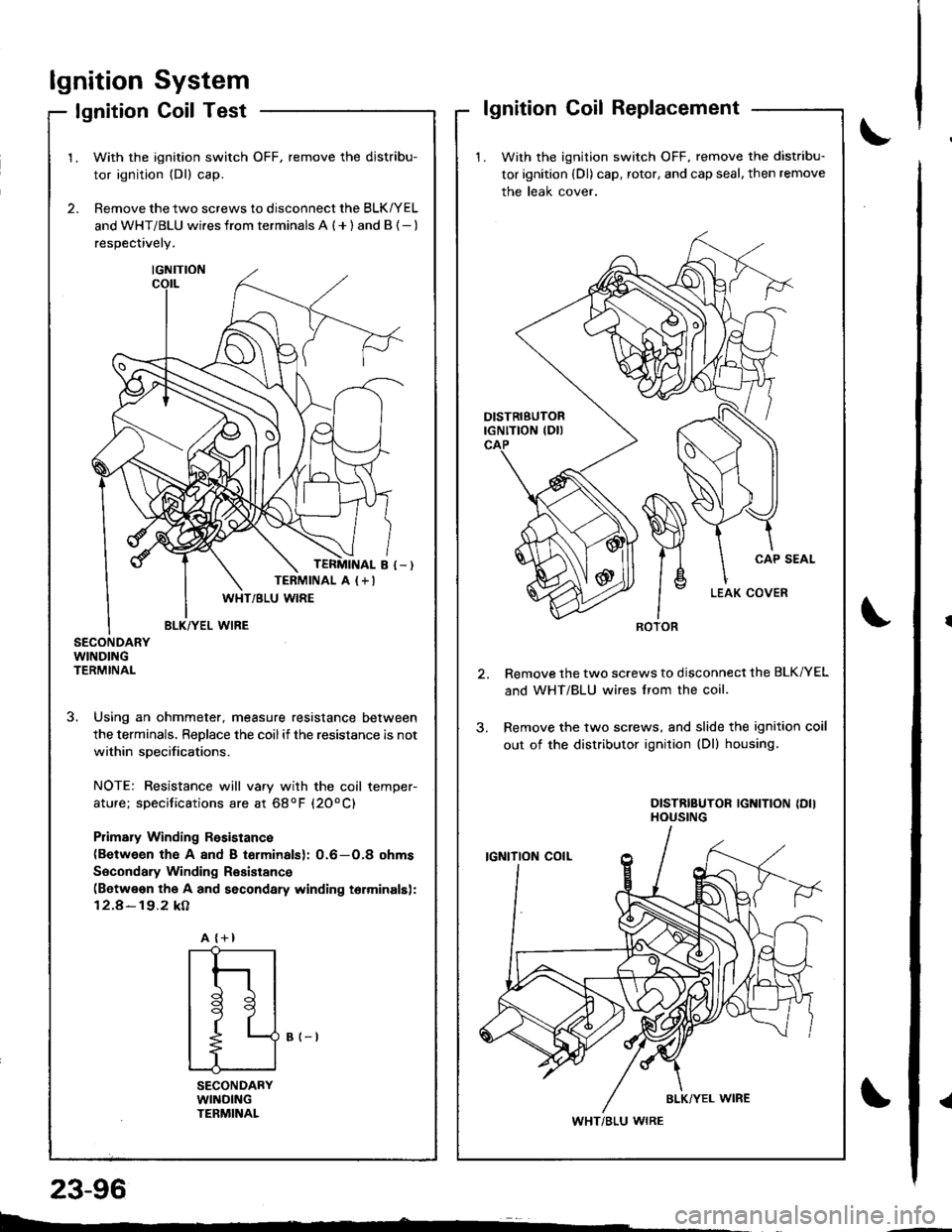
1. With the ignition switch OFF, remove the distribu-
tor ignition (Dl) cap, rotor, and cap seal, then remove
the leak cover.
Remove the two screws to disconnect the BLK/YEL
and WHT/BLU wires lrom the coil.
Remove the two screws, and slide the ignition coil
out of the distributor ignition (Dl) housing.
DISTRIBUTOR IGNITION {DIIHOUSING
ROTOR
WHT/BLU WIRE
2.
1.With the ignition switch OFF, remove the distribu-
tor ignition (Dl) cap.
Remove the two screws to disconnect the BLK/YEL
and WHT/BLU wi.es from terminals A ( + ) and B {- )
respectively.
SECONDARYWINDINGTERMINAL
3. Using an ohmmeter, measure resistance between
the terminals. ReDlace the coilif the resistance is not
within soecifications.
NOTE: Resistance will vary with the coil temper-
ature; specifications are at 68oF (20oC)
Plimary Winding Rssistance(Between th€ A 8nd B torminalsl: 0.6-O,8 ohms
Socondary Winding Resistance(Betwe€n the A and secondary winding torminalsl:
12.4-19.2 kA
B (-t
SECONDARYWllrlDlNGTENMINAL
TERMINAL A (+I
A {+}
{
t
l
tl
t9
t
L--
23-96
Page 1154 of 1681
lgnition Control Module (lCM) Input Test
NOTE:
a See section 1 1 if the malfunction indicator lamp (MlLl
has been reported on.a Perform an input test for the ignition control module(lCM) after finishing the fundamental tests for the ig-nition system and the fuel and emissions systems.a The tachometer should operate normally.
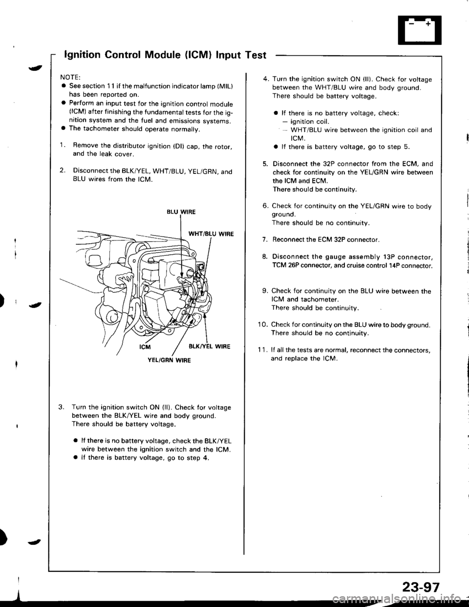
1. Remove the distributo. ignition (Dl) cap, the rotor,and the leak cover.
2. Disconnect the BLK/YEL, WHT/BLU, YEL/GRN, andBLU wires from the lCM.
3. Turn the ignition switch ON {ll}. Check for voltage
between the BLK/YEL wire and body ground.
There should be battery voltage.
a lf there is no battery voltage, check the BLKiYEL
wire between the ignition switch and the lCM.a It there is battery voltage, go to step 4,
)
I
)
BLU WIRE
YEL/GRN I,\'IRE
4. Turn the ignition switch ON (ll). Check for voltage
between the WHT/BLU wire and body ground.
There should be battery voltage.
a lf there is no battery voltage, check:- ignition coil.- WHT/BLU wire between the ignition coil and
tcM.
a lf there is battery voltage, go to step 5.
5. Disconnect the 32P connector from the ECM, and
check for continuity on the YEUGRN wire between
the ICM and ECM.
There should be continuity.
6. Check for continuity on the YEL/GRN wire to bodygrouno.
There should be no continuity.
7.Reconnect the ECM 32P connector.
Disconnect the gauge assembly 13P connector,
TCM 26P connector, and cruise control l4P connector.
9. Check for continuity on the BLU wire between the
ICM and tachometer.
There should be continuity.
'10. Check for continuity on the BLU wire to body ground.
There should be no continuity.
1 1 . lf all the tests are normal, reconnect the connectors,
and replace the lCM.
23-97
/i
Page 1155 of 1681
lgnition System
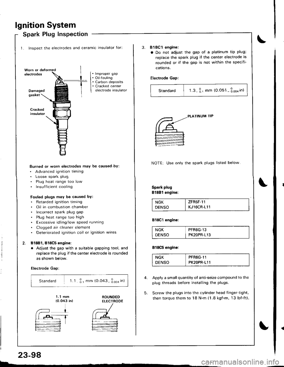
1. Inspect the electrodes and ceramic insulator for:
Spark Plug lnspection
. lmproper gap. Oil-fouling. Carbon deposits. Cracked centerelectrode insulatorDamagedgaskei
Burned or worn electrodes may be caused by:
. Advanced ignition timing. Loose spark plug
. Plug heat range too low. Insufficient cooling
Fouled plugs may be caused bY:. Retarded ignition liming. Oil in combustion chamber. Incorrect spark plug gap
. Plug heat range too high. Excessive rdling'low speed running
. Clogged air cleaner element. Deteriorated ignition coil or ignition wires
81881, 818C5 engine:
. Adjust the gap wjth a suitable gapping tool, and
replace the plug if the center electrode is rounded
as shown below.
Electrode Gap:
Standard 'l .1 ; r mm {0.043 ; ooa in)
E.
23-98
3.818C1 engine:
a Do not adjust the gap ol a platinum tip plug;
replace the spark plug it the center electrode is
rounded or if the gap is not within the specifi-
cattons.
Electrode Gap:
Standard I t.s-3., mm (0.051-3.oo4in)
5.
PLATINUM TIP
NOTE: Use onlv the spark plugs listed below
Spark plug
Bl88l engine:
NGK I ZFR5F-11
DENSO I KJ 16CR-111
818C1 engine:
NGK PFR6G-13
DENSO I PK2OPR-113
818C5 engine:
NGK PFR6G-I1
DENSO PK2OPR-111
Apply a small quantity ot anti-seize compound to the
plug threads belore installing the plugs.
Screw the plugs into the cylinder head tinger tight,
then torque them to 18 N.m (1 .8 kgf.m, 13lbf.ft).
Page 1156 of 1681

)
)
Charging System
Component Locationlndex
CHARGING SYSTEM LIGHT(ln the gauge assembly)Test, pages 23-102,103Bulb Locations, page 23-122
UNDER-HOOD FUSE/RELAY BOX(USA: HAS bUiIt-iN ELECTRICALLOAD DETECTOR (ELD) UNIT}Troubleshooting of ELD, secrion 11
BATTERYTest,
ALTERNATOR BELTInsp€ction and Adiustment, page 23_115ALTERNATORTroubleshooting, page 23'102Alternator/FegulatorTosl, pages 23-105,'106Replacement, page 107Overhaul, page 23-108
23-99
.t-
Page 1157 of 1681
a
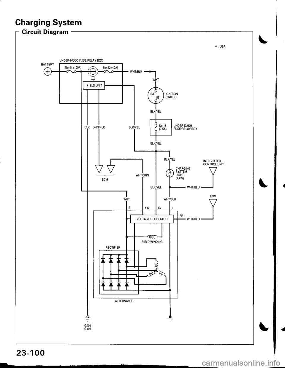
Charging System
Circuit Diagram
INTEGRATEOCONTROL UNIT
V
II
ECM
V
II
UNDER.HOOD FUSE/RELAY BOX
No41 (1tl0A) /^ N0.42 (40A)
FIETDWINOING
WHT/8LU
L
GFN/REO
I
I
I
I-t
-"
ALTERNATOR
BLK/YEL
23-100
I-
Page 1158 of 1681
*l
I/'1\
/ ari orrr or cr / swlrcH
vIBtKAEtI
rt-r| ) m.rs IUNDER-DASHI t (7.5A) |FUSE/RELAYBOX
IBLK,YEL
-i * TNTEGBATEo
I CoNTROL UN|T
rh 3i{i3#' v
Ynu i
| ,."
UNDEH.HOOD FUSE/RELAY BOX
No.4l (100A) ,.4 No 42 (40A)
B FTELDWTNoTNG
ECM
WHT/8LU
L
ALTERNATOF
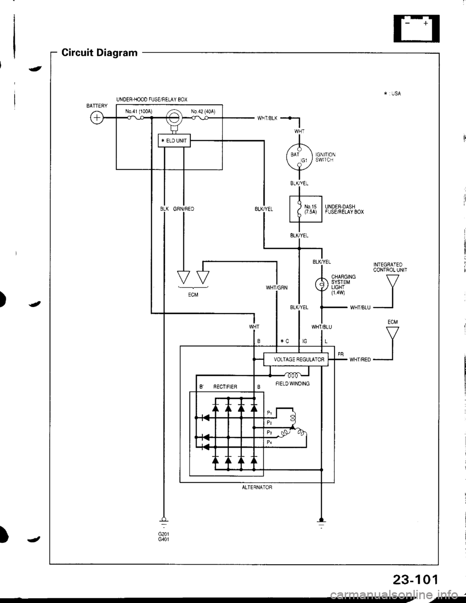
Circuit Diagram
)
-
-
)
23-101
,f
Page 1159 of 1681
Charging System
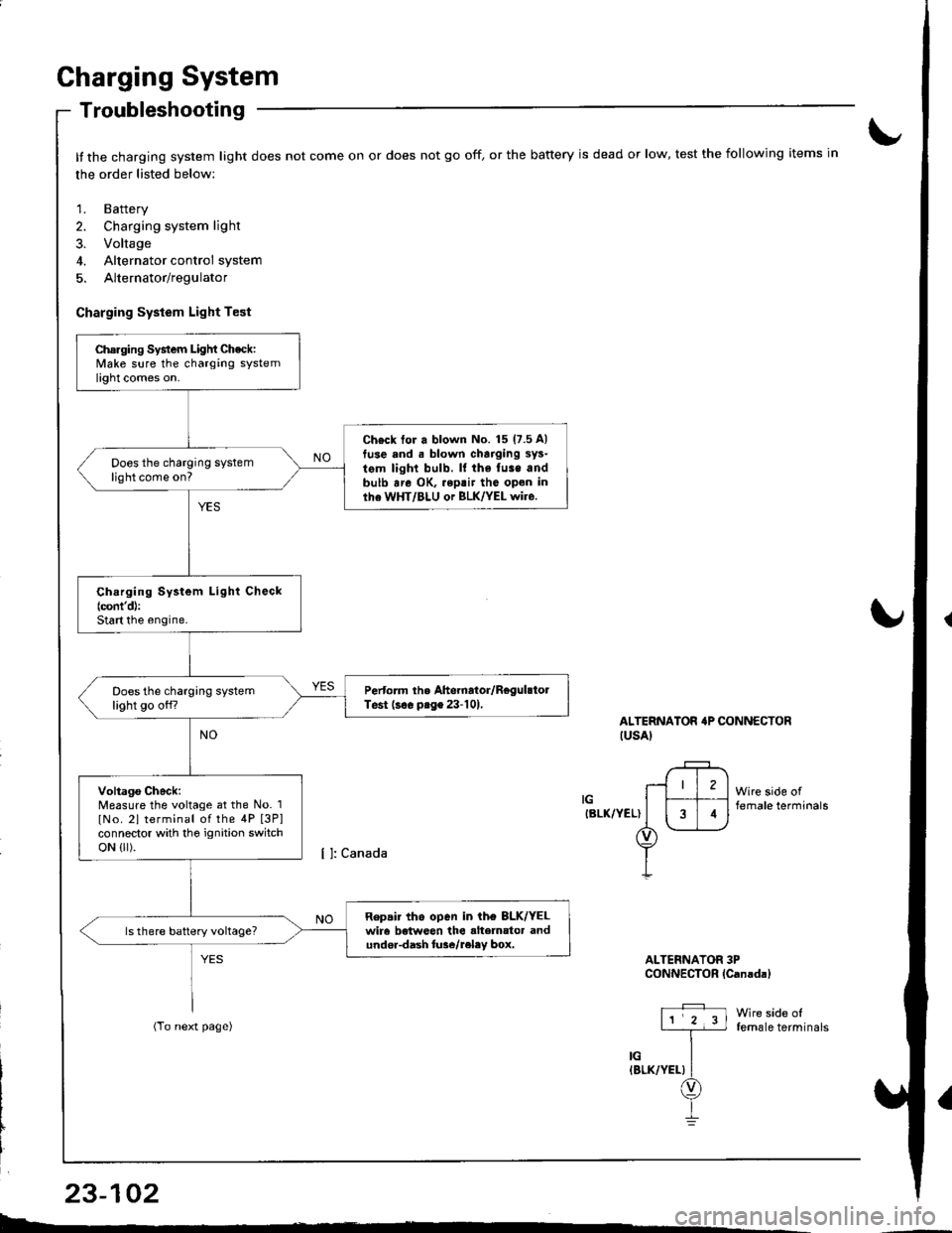
Troubleshooting
It the charging system light does not come on or does not go off, or the battery is dead or low, test the following items in
the order listed below:
1. Battery
2. Charging system light
3. Voltage
4. Alternator control system
5. Alternator/regulator
Charging System Light Test
ALTERNATOR'P CONNECTORIUSAI
IGIBLK/YEL)
Wire side offemale terminals
Wire side offemale terminals
ALTERNATOR 3PCONNECTOR lCanadal
Charging System Light Check:Make sure the charging systemlight comes on.
Ch€ck tor a blown No. 15 (7.5 A)
tuse and . blown charging sys-
tem light bulb. ll the fuse andbulb are OK, .eptir tho open inlhe WHT/BLU or BLK/YEL wire.
Does the charging systemlight come on?
Ch.rging System Light Check(cont'd):
Start the engine.
Pertorm the Ahernator/RegulstolTest (s€. prge 23-101,Does the charging systemlight go off?
Voltago Check:Measure the voltage at the No. 1
lNo. 2l terminal of the 4P [3P]connector with tho ignition switchoN {lr).
Repair tho open in ih€ 8LK/YELwir6 betweon the alte]nator andundor-dash lure/reley box.
I4
L-*
23-102
Page 1160 of 1681
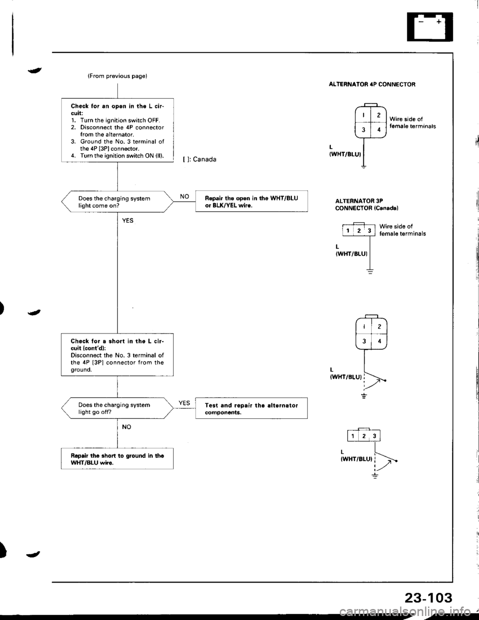
{From previous page}
Repai. ths open in tho WHT/ALUor BLK/YEL wir€.Does the charging systemlight come on?
Chock tor a sho.l in the L cir-cuit lcont'd):Disconnect the No.3 terminal ofthe 4P [3Pl connector from theground.
Does the charging systemlight go offi
Repair the shon to ground in thoWHT/BLU wiro.
{
t
Check for an opon in lhe L cir-cuit:1. Turn the ignition switch OFF.2. Disconnect the 4P connectorfrom the alternator.3. Ground the No. 3 terminal ofthe 4P [3Plconnector.4. Turn the ignition switch ON (ll).
ALTERNATOB irP CONNECTOR
ALTERNATOR 3PCONNECTOR {Canadal
11 2 3l
,l
iin"vr.rr\
Wire side oftemale t€rminals
[ ]: Canada
LIWHT/BLUI
LIWHT/BLU)
Wire side offemale terminals
)
23-103
4
--