HONDA INTEGRA 1998 4.G Workshop Manual
INTEGRA 1998 4.G
HONDA
HONDA
https://www.carmanualsonline.info/img/13/6069/w960_6069-0.png
HONDA INTEGRA 1998 4.G Workshop Manual
Trending: steering wheel adjustment, wheel torque, oil, checking oil, warranty, check transmission fluid, service
Page 1141 of 1681
Starting System
Armature Inspection and Test (cont'd)
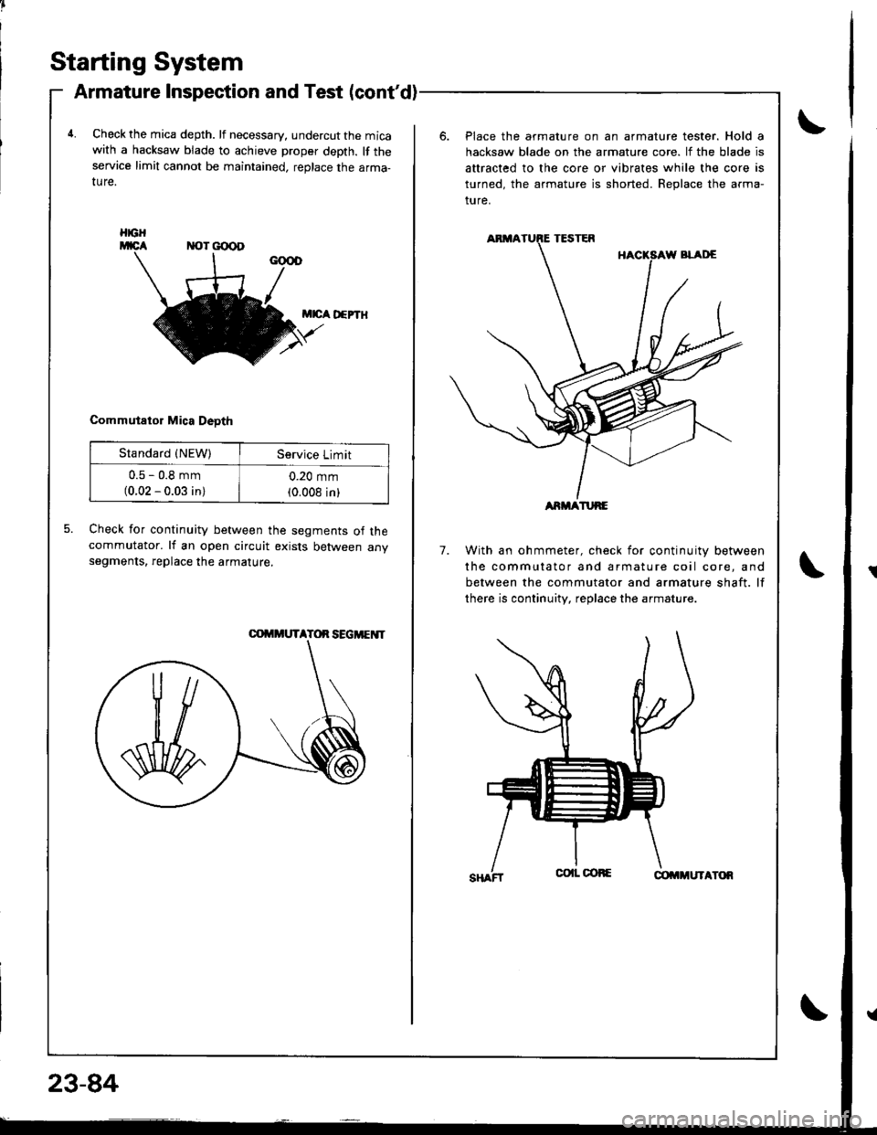
4.Check the mica depth. lf necessary, undercut the micawith a hacksaw blade to achieve proper depth. lf theservice limit cannot be maintained, replace the arma-ture.
Place the armature on an armature tester. Hold a
hacksaw blade on the armature core. lf the blade is
attracted to the core or vibrates while the core is
turned, the armature is shorted. Beplace the arma-
ture.
M|cA D€PTH
Commutator Mica Deoth
5.Check for continuity between the segments of thecommutator. lf an open circuit exists between anvsegments, replace the armature.7.With an ohmmeter, check for continuity between
the commutator and armature coil core, and
between the commutator and armature shaft. lf
there is continuity, replace the armature.
HGH
Standard {NEW)Service Limit
u.5 - u,6 mm(0.02 - 0.03 in)
0.20 mm(0.008 inlARMATURE
Page 1142 of 1681
BRUSHES
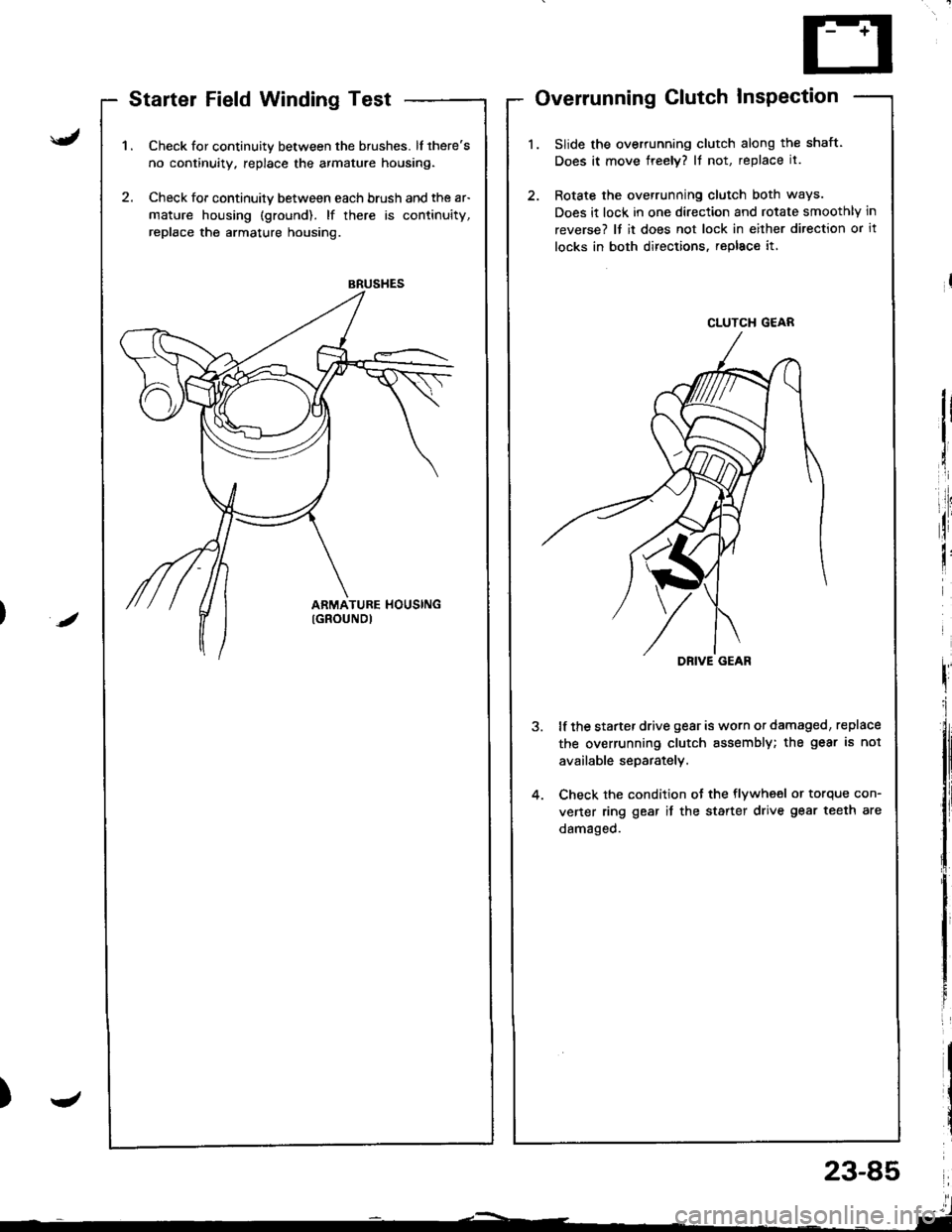
Startel Field Winding Test
Check for continuity between the brushes. lf there's
no continuity. replace the armature housing.
Check for continuily between each brush and the ar-
mature housing (ground). lf there is continuity,
replace the armature housing.
Overrunning Clutch InsPection
Slide the overrunning clutch along the shaft.
Does it move freely? It not, replace it.
Rotate the overrunning clutch both ways.
Does it lock in one direction and rotate smoothly in
reverse? It it does not lock in either direction or it
locks in both directions, repl8c€ it,
lf the starter drive gear is worn or damaged, replace
the overrunning clutch assembly; the gear is not
available separately.
Check the condition ot the flywheel or torque con-
vener ring gear it the starter drive gear teeth are
damaged.
/
J
CLUTCH G€AR
DRIVE GEAR
23-85
l'l- ,-----_ -'l
Page 1143 of 1681
Starter Reassembly
Starting System
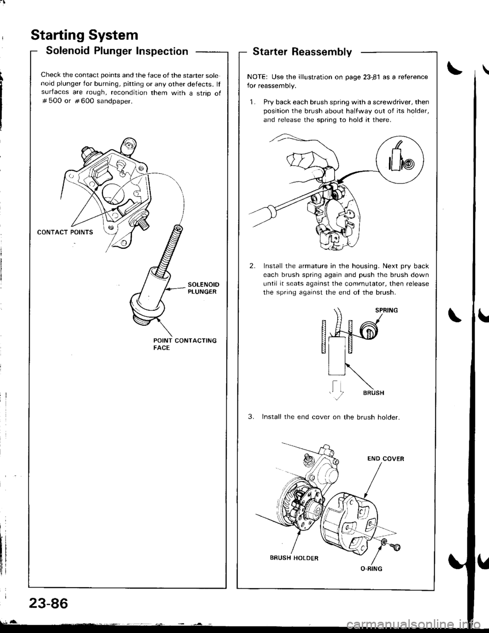
Solenoid Plunger Inspection
Check the contact points and the face of the starter solenoid plunger for burning, pitting or any other defects. lfsurfaces are rough, recondition them with a strip of# 500 or # 600 sandoaoer.
POINT CONTACTINGFACE
NOTE: Use the illustration on page 23-81 as a reference
for reassembly.
1. Pry back each brush spring with a screwdriver, then
position the brush about halfway out of its holder,
and release the spnng to hold it there.
2. Install the armature in the housing. Next pry back
each brush spring again and push the brush down
until it seats against the commutator. then release
the spring against the end ol the brush.
SPRTNG
fi49-d
EI
VIR, ,\
li N,."
3. lnstall the end cover on the brush holder.
O-RING
23-86
Page 1144 of 1681
J
Starting System
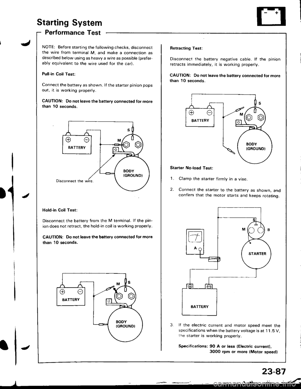
Performance Test
NOTE: Before starting the following checks, disconnectthe wire from terminal M, and make a connection asdescribed below using as heavy a wire as possible (prefer
ably equivalent to the wire used for the car).
Pull-in Coil Test:
Connect the battery as shown. If the starter pinion pops
out, it is working properly.
CAUTION: Do not leave the battery connectsd Jor morethan 1O seconds.
Hold-in Coil Test:
Disconnect the battery from the M terminal. lf the pin-
ion does not retract, the hold-in coil is working properly.
CAUTION: Do not leave the battery connected for more
than 10 seconds.
J
Retracting Test:
Disconnect the battery negative cable. lf the pinion
retracts immediately, it is working properly.
CAUTION: Do not leave the battery connected fol more
than 1O seconds.
Starter No]oad Test:
1. Clamp the starter firmly in a vise.
2. Connect the starter to the battery as shown, andconfirm that the motor starts and keeps rotating.
3 lf the electric current and motor soeed meet thespecifications when the battery voltage is at 1 1.5 V,the starter is working properly.
Sp€cifications: 9O A or less (Electric currentl,
3O0O rpm or more {Motor speed}
Page 1145 of 1681
lgnition System
23-88
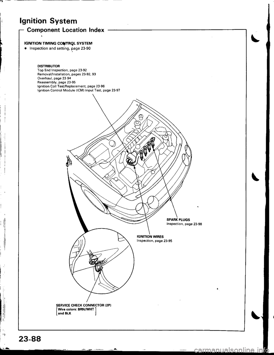
Component Location lndex
rGNlTroN TTMTNG COJTRqL SYSTEM
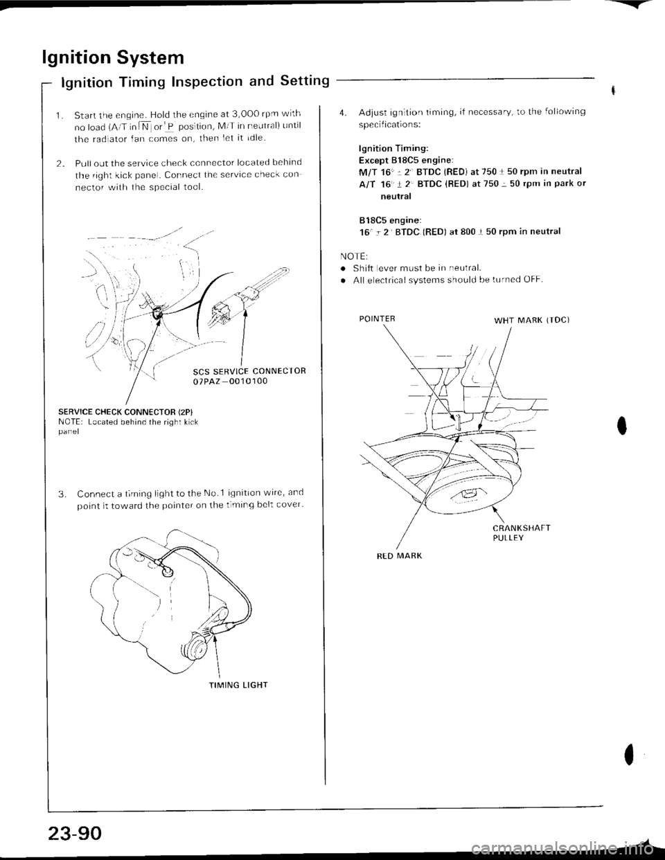
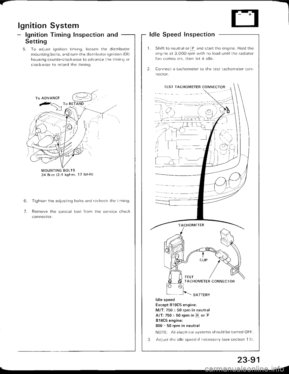
. lnspection and sefting, page 23-90
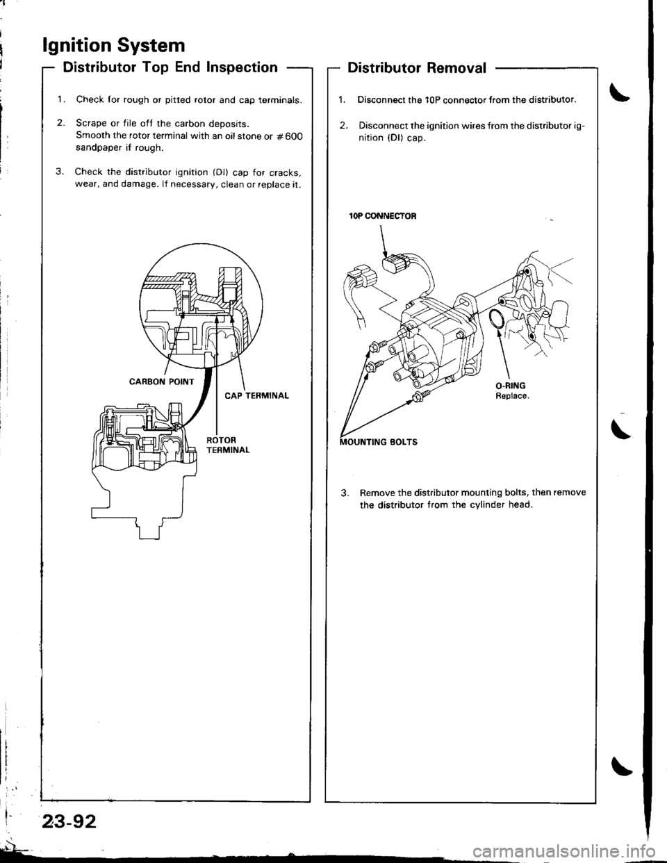
DISTRIBUTORTop End lnspeclion, page 23-92Removal/lnstallation, pages 23-92, 93Overhaul, page 23 94Reassembly, page 23-95lgnition Coil TesvReplacement, page 23 96lgnition Control Module (lCM) lnput Test, page 23-97
PLUGSInspection, pago 23-98
IGN'TION WIRESInspection, page 23-95
SERVICE CHECK CONNECTOR I2PIIWi]6 coloEi BRN/WHT I
land BLK j
Page 1146 of 1681
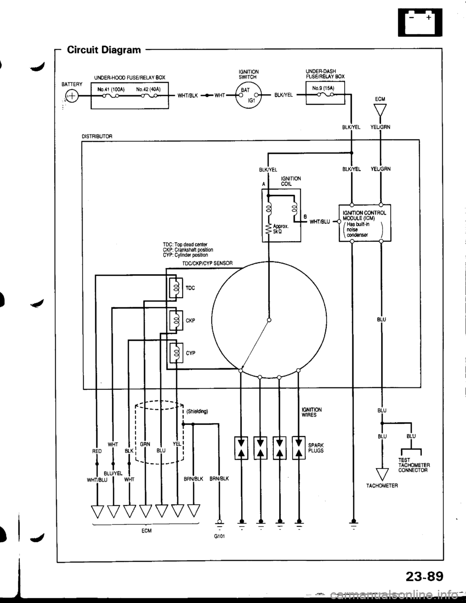
ECM
VI
BLU
I
BI.U 8LUll
I --r
I li3fou.'..
v
coNNEcroR
TACHOMETER
UNOER.DASHruSARELAY BOX
l-*",t^l
t*Tl-l
I
IGNTTIONWlRES
llI SPANKI PLUGS
t uragram -
UNDER.HOOO FUSgRELAY 8OX
-i.i,
T}
23-89
Page 1147 of 1681
Page 1148 of 1681
Page 1149 of 1681
Page 1150 of 1681
Trending: oil change, steering, jump start terminals, warning light, Photo c503, turn signal bulb, refrigerant type
