HONDA INTEGRA 1998 4.G Workshop Manual
INTEGRA 1998 4.G
HONDA
HONDA
https://www.carmanualsonline.info/img/13/6069/w960_6069-0.png
HONDA INTEGRA 1998 4.G Workshop Manual
Trending: odometer, Power steering pump, fuse box, fuses, ground, manual radio set, transmission oil
Page 1261 of 1681
Stereo Sound System
Mast Antenna Installation
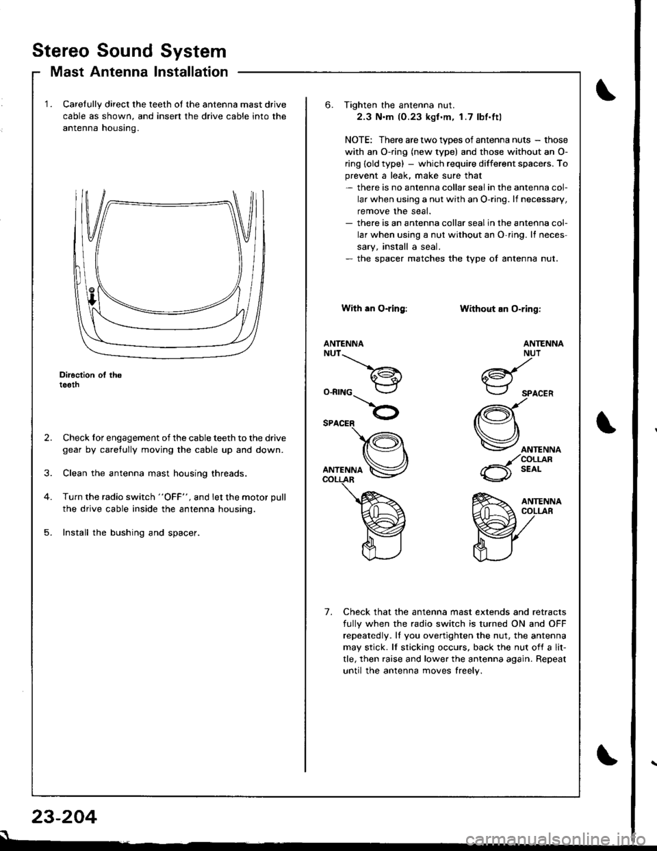
Carelully direct the teeth of the antenna mast drive
cable as shown, and insert the drive cable into the
antenna housino.
Diroction ol th6teeth
Check for engagement of the cable teeth to the drive
gear by caretully moving the cable up and down.
Clean the antenna mast housing threads.
Turn the radio switch "OFF", and let the motor pull
the drive cable inside the antenna housing.
Install the bushing and spacer.
23-204
s
6. Tighten the antenna nut.
2.3 N.m (0.23 kgf .m. 1.7 lbf.ftl
NOTE: There are two types of antenna nuts - those
with an O-ring (new type) and those without an O-
ring (old type) - which require different space.s. To
prevent a leak, make sure that- there is no antenna collar seal in the antenna col-
lar when using a nut with an O-ring. lf necessary,
remove the seal.- there is an antenna collar sealin the antenna col-
lar when using a nut without an O-ring. It neces-
sary, install a seal.- the spacer matches the type of antenna nut.
With an O-ring:
ANTENNANUT__.\
a€^1.i*-lr
O-RING
Without an O-ring:
ANTENNA
ANTENNANUT
6d{.i*-.-r
SPACER
(Q\
Vorr.""o
_/coLrjlR
6 t'o'-
Check that the antenna mast extends and retracts
fully when the radio switch is turned ON and OFF
repeatedly. ll you overtighten the nut, the antenna
may stick. lf sticking occurs. back the nut of{ a lit-
tle, then raise and lower the antenna again. Repeat
until the antenna moves freely.
7.
Page 1262 of 1681
J
)
I
4.
2.
1.
5.
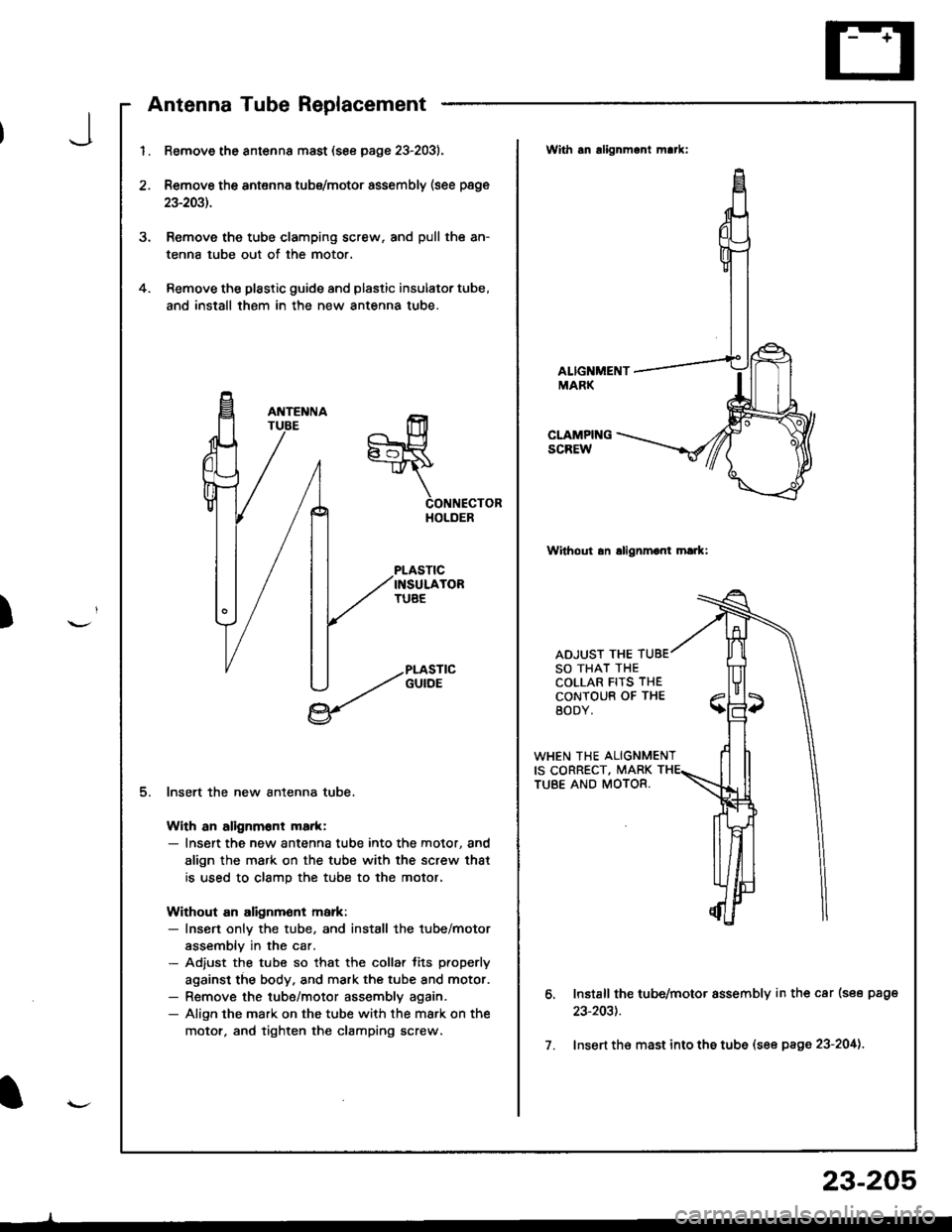
Remove the antsnna mast (see page 23-2031.
Remove the antenna tubs/motor assembly (see page
23-2031.
Remove the tube clamping screw, and pull the an-
tenna tube out of the motor.
Remove the plastic guide and plastic insulator tube,
and install them in the new antenna tube.
CONNECTORHOLDER
PLASTICINSULATORTUAE
PLASTICGUIOE
lnsert the new antenna tube.
With an alignm6nt ma.k:- Insert the new antenna tube into the motor, and
align the mark on the tube with the screw that
is used to clamp the tube to the motor,
Without an alignmont markr- Insen onlv the tube, and install the tube/motor
assemblv in the car.- Adjust the tube so that the collar lits properly
against the body. and mark the tube and motor.- Remove the tube/motor assembly again.- Align the mark on the tube with the mark on the
motor, and tighten the clamping screw.
With an alignmant m!*:
ALIGNMENTMARK
CLAMPINGSCREW
Wilhout an allgnmont hark:
ADJUST THESO THAT THECOLLAR FITS THECONTOUB OF THEBODY.
WHEN THE ALIGNMENTIS CORRECT, MARKTUBE AND MOTOR.
o.
7.
Install the tub6/motor assembly in th€ car (see page
23-203t.
Insert th€ mast into ths tube (see page 23-204).
23-205
Page 1263 of 1681
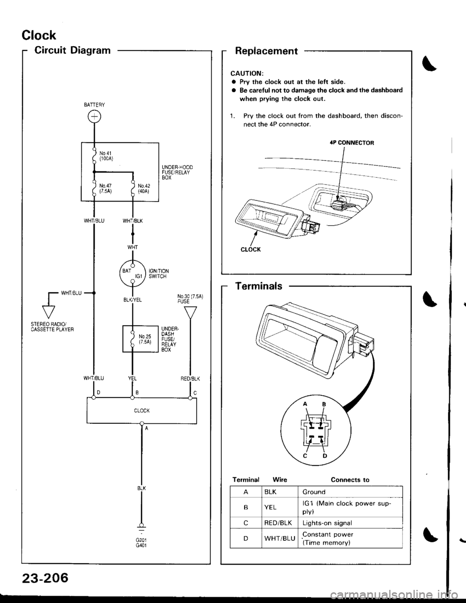
Clock
CircuitDiagram
CAUTION:
a Prv the clock out at the left side.
a Be careful not to damage the clock and the dashboard
when prying the clock out.
1. Pry the clock out from the dashboard. then discon-
nect the 4P connector.
4P CONNECTOR
CLOCK
BATTERY
UNDER,HOODFUSE/RELAYBOX
WI-]T/BLK
I
A/ BAT I 1GN TION
Y*"t No3o(7.sA)-|" -v
F'nrrn l
I
WHT/BLU
l- wHT 8LU
al-
STEREO BADIOiCASSETTE PLAYEF
BLK
G201G401
BLKGround
BYELrG1
pry,
(Main clock power sup-
cRE D/BLKLights-on signal
DWHT/BLUConstant power
(Time memory)
Terminals
23-206
Page 1264 of 1681
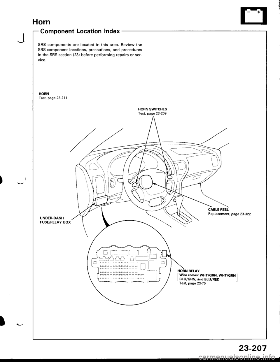
Horn
Component Location lndex
JSRS components are located in this area. Review the
SRS component locations, precautions, and procedures
in the SRS section {23) before performing repairs or ser-
vtce,
HORNTest, page 23 211
HORN SWITCHESTest, page 23-209
CABLE REELReplacement, page 23 322UNDER-DASHFUSE/BELAY BOX
{---=-\s":=',-i=
il
-rrj _LJLi lJJJ I -.r ----------;- - t--t -----,------- L I t---HORN RELAY
I Wire colo6: WHT/GRN, WHT/GRN ILBLU/GRN, and BLU/REO ITest, page 23-70
)
23-207
Page 1265 of 1681
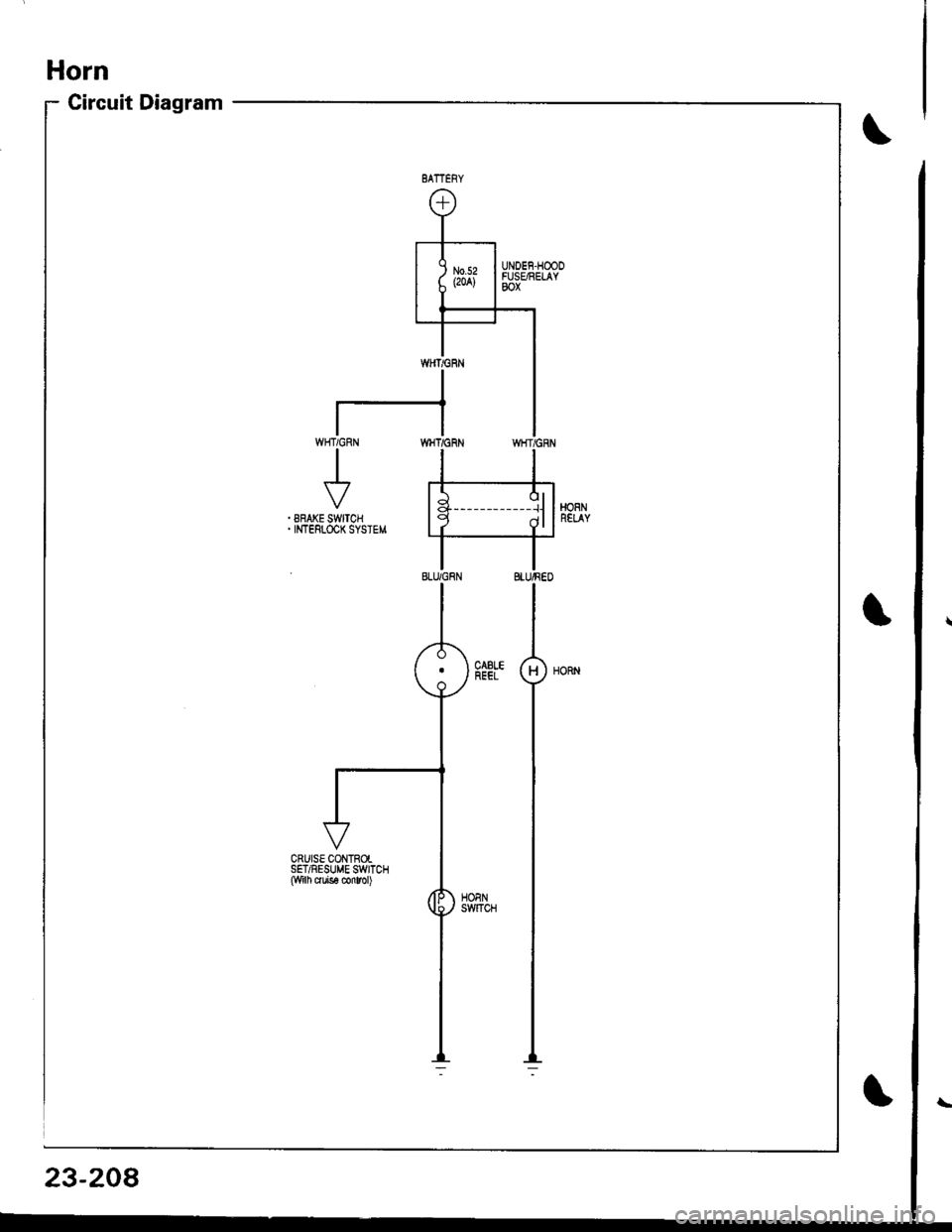
UNOEF.HOODFUSARELAYBOX
CRUISE CONTROISET/RESUME SWTCH($/-ih c.ute conrol)
23-208
Page 1266 of 1681
SwitchTest
SRS comDonents are located in this area. Review the
SRS component locations, precautions, and procedures
in the SRS section (23) before performing repairs or ser-
vtce.
NOTE: The original radio has a coded thett protection cir-
cuit. Be sure to get the customer's code number beJore- disconnecting the battery.- removing the No. 47 (7.5 A) fuse from the under-hood
fuse/relay box.- removing the radio.
After service, reconnect Dower to the radio and turn it on.
When the word "CODE" is displayed, enter the customer's
5-digit code to restore radio operation
Disconnect the battery negative cable, then discon-
nect the positive cable, and wait at least three min-
uIes.
Disconnect each airbag connector.
Driver's Side:
a Remove the access panel from the steering wheel,
then disconnect the 2P connector between the
driver's airbag and cable reel.
Front Passenger's Side:
. Remove the glove box,
a Disconnect the 2P connector between the front
passenger's airbag and SRS main harness.
1.
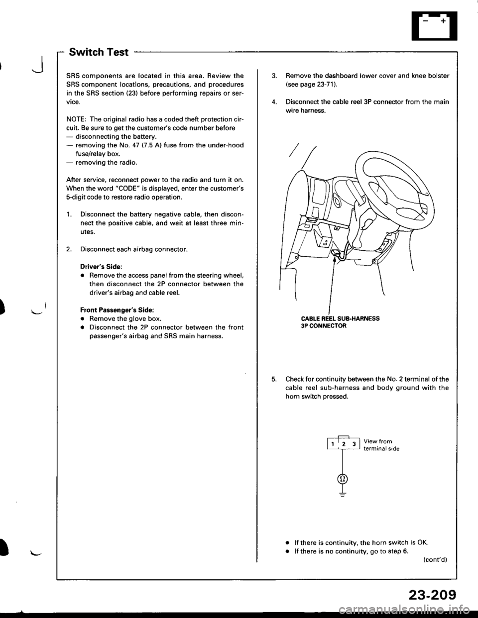
Remove the dashboard lower cover and knee bolster(see page 23-71).
Disconnect the cable reel 3P conneclor from the main
wtre narness.
CABLE REEL SUB.HARNESS3P CONNECTOR
Check for continuitv between the No. 2 terminal of the
cable reel sub-harness and body ground with the
horn switch Dressed.
terminalside
a
It there is continuity, the horn switch is OK.
lf there is no continuity, go to step 6. (cont,d)
r-P r11 2 3l-t-
I
I\-J
)
I
23-209
Page 1267 of 1681
Horn
Switch Test (cont'd)
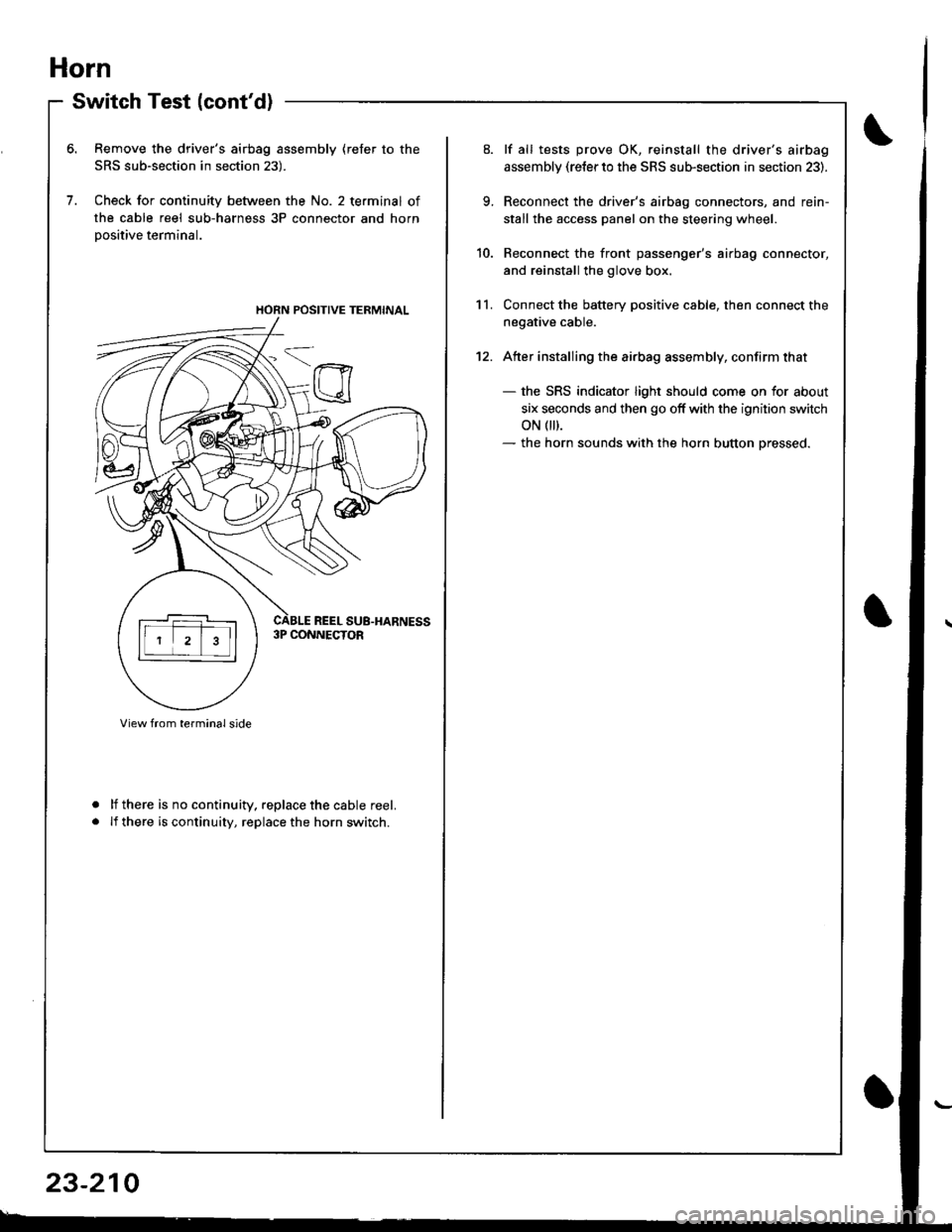
Remove the driver's airbag assembly (refer to the
SRS sub-section in section 23).
Check for continuity between the No. 2 terminal of
the cable reel sub-harness 3P connector and horn
Dositive terminal.
lf there is no continuity. replace the cable reel.
lf there is continuity, replace the horn switch.
a
a
HORN POSITIVE TERMINAL
23-210
9.
10.
11.
12.
lf all tests prove OK, reinstall the driver's airbag
assembly (re{er to the SRS sub-section in section 23).
Reconnect the driver's airbag connectors, and rein-
stall the access panel on the steering wheel.
Reconnect the front passenger's airbag connector,
and reinstall the glove box.
Connect the battery positive cable, then connect the
negative cable.
Atter installing the airbag assembly, confirm that
- the SRS indicator light should come on for about
six seconds and then go off with the ignition switch
oN 0t).- the horn sounds with the horn button pressed.
Page 1268 of 1681
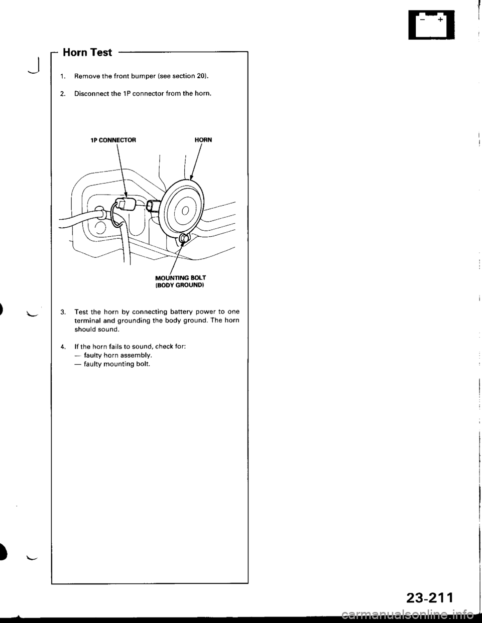
Horn Test
1.Remove the front bumper (see section 20).
Disconnect the 1P connector from the horn.
lP CONNECTOR
MOUNNNG BOLT
IBODY GROUND}
Test the horn by connecting battery power to one
terminal and grounding the body ground. The horn
should sound.
lf the horn fails to sound, check tor:- taulty horn assembly.- faulty mounting bolt.
J
Page 1269 of 1681
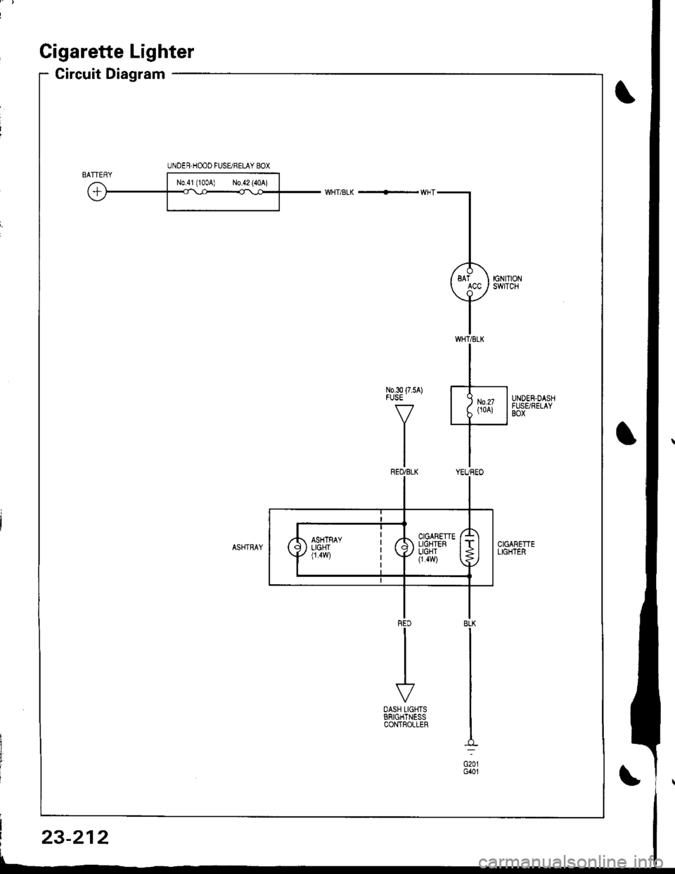
Gigarette Lighter
Circuit Diagram
UNDER.HOOD FUSURELAY 8OX
3o{75A) J-
Y
Lit*is***/
I
r'
OASH LIGHTSERIGHTNESSCONTFOLLER
BLK
G201G401
23-212
Page 1270 of 1681
J
)
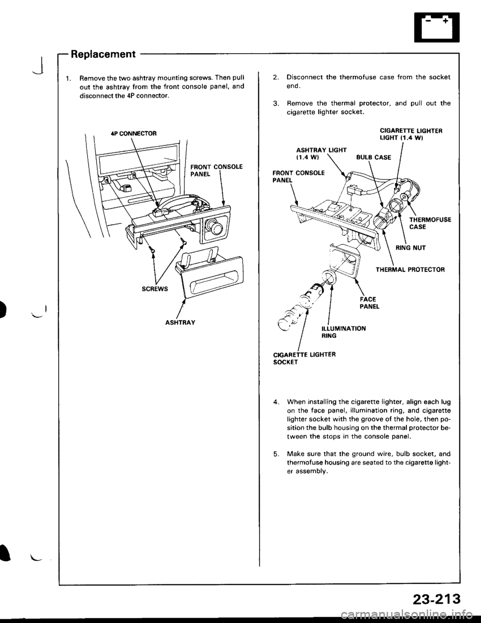
1.Remove the two ashtray mounting screws. Then pull
out the ashtray from the front console panel. and
disconnect the 4P connector.
2.Disconnect the thermofuse case from the
end.
Remove the thermal protector, and pull
cigarette lighter socket.
socket
out the
CIGARETTE LIGHTERLTGHT t1.4 Wl
ASHTRAY LIGHTt1.4 WlEULB CASE
FRONT CONSOLEPANEL
THERMOFUSECASE
RING NUT
THERMAL PROTECTOR
scREws
ILLUMINATIONRING
CrcANETTE LIGHTERsocxET
When installing the cigarette lighter, align each lug
on the face panel, illumination ring, and cigarette
lighter socket with the groove of the hole. then po-
sition the bulb housing on the thermal protector be-
tween the stops in the console panel.
Make sure that the ground wire, bulb socket, and
thermofuse housing are seated to the cigarette light-
er assembly.
5.
ASHTRAY
l\-
23-213
Trending: coolant level, fuel pump, maintenance, fuel type, Photo 79, check oil, window


