check engine HONDA INTEGRA 1998 4.G User Guide
[x] Cancel search | Manufacturer: HONDA, Model Year: 1998, Model line: INTEGRA, Model: HONDA INTEGRA 1998 4.GPages: 1681, PDF Size: 54.22 MB
Page 163 of 1681
I
7.
8.
9.
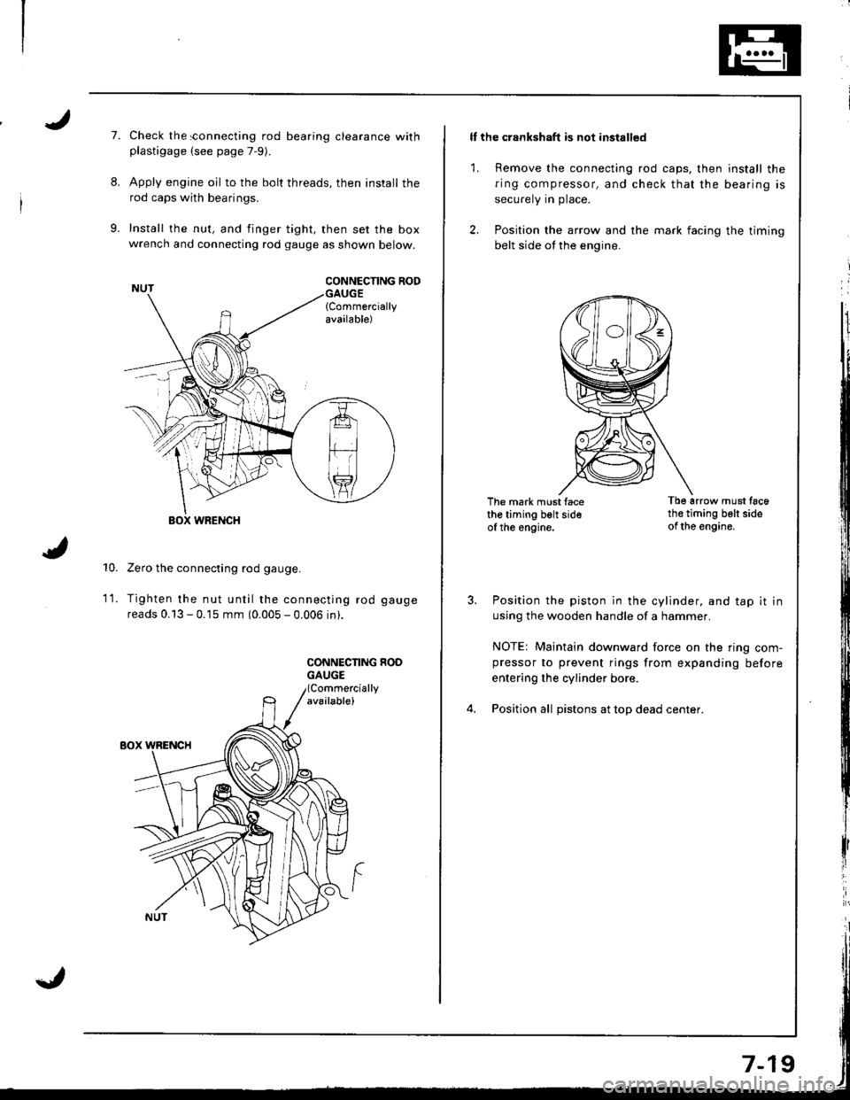
Check the sonnecting rod bearing clearance withplastigage (see page 7-9).
Apply engine oil to the bolt threads, then install the
rod caps with bearings.
Install the nut, and finger tight, then set the boxwrench and connecting rod gauge as shown below.
CONNCCNNG RODGAUGE{Commerciallyavailable)
10.
WRENCH
Zero the connecting rod gauge.
Tighten the nut until the connecting rod gauge
reads 0.13 - 0.15 mm (0.005 - 0.006 in).
CONNECNNG HOOGAUGE
1t.
ll the crankshaft is not installed
1. Remove the connecting rod caps, then install the
ring compressor, and check that the bearing is
securely in place.
2. Position the arrow and the mark facing the timing
belt side ot the engine.
The mark must facethe timing belt sideof the engine.
Tb6 arrow must tac6th€ timing belt sideof the engine.
Position the piston in the cylinder, and tap it in
using the wooden handle of a hammer.
NOTE: Maintain downward force on the ring com-pressor to prevent rings from expanding before
entering the cylinder bore.
Position all pistons at top dead center.
Page 164 of 1681
Piston Rings
Replacement
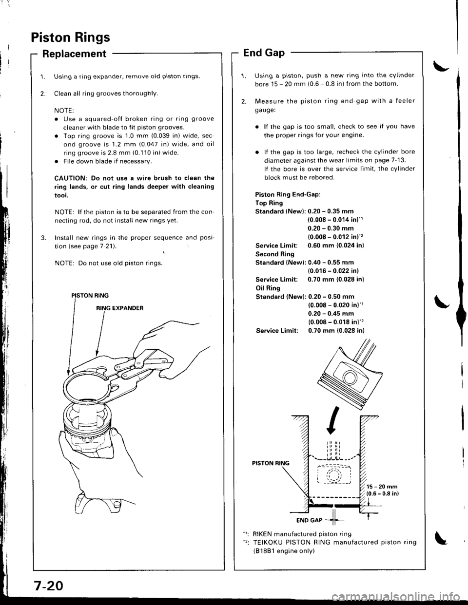
Using a ring expander, remove old piston rlngs.
Clean all ring grooves thoroughly.
o Use a squared-ofl broken ring or ring groove
cleaner with blade to fit piston grooves.
. lop ring groove is 1.0 mm (0.039 in) wide, sec
ond groove is 1.2 mm (0.047 in) wide, and oil
ring groove is 2.8 mm (0.110 in) wide.
. File down blade if necessary.
CAUTION: Do not use a wire brush to clean the
ring lands, or cut ring lands deeper with cleaning
tool.
NOTE: lf the piston is to be separated from the con
necting rod, do not install new rings yet.
Install new rings in the proper sequence and posa-
tion (see page 7 21).
Do not use old piston rings.
PISTON RING
End Gap
Using a piston, push a new ring into the cvlinder
bore 15 - 20 mm 10.6 0.8 in) f rom the bottom.
2. N,4easure the piston ring end gap with a feeler
gauge:
lf the gap is too small, check to see if you have
the proper rings for your engine.
. lf the gap is too large, recheck the cylinder bore
diameter against the wear limits on page 7-13.
lf the bore is over the service limit, the cylinder
block must be rebored.
Piston Ring End-Gap:
Top Ring
Standard (New):0.20 - 0.35 mm
(0.008 - 0.014 inl'1
0.20 - 0.30 mm
{0.008 - 0.012 in}''�
Service Limit: 0.60 mm {0.024 in)
Second Ring
Standard {New): 0.40 - 0.55 mm
{0.016 - 0.022 inl
Service Limit: 0.70 mm {0.028 inl
Oil Ring
Standard (New): 0.20 - 0.50 mm
10.008 - 0.020 in)'r
0.20 - 0.45 mm
(0.008 - 0.018 in)''�
Service Limit: 0.70 mm (0.028 in)
PISTON RING
15-20mm{0.6 - 0.8 in)
RIKEN manufactured piston ring
TEIKOKU PISTON RING manufactured piston ring
(B 1881 engine only)
Page 168 of 1681
Inspection (cont'dl
3.
4.
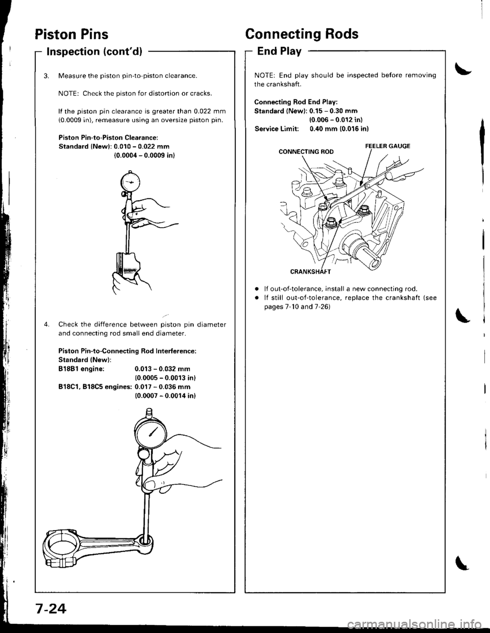
Measure the piston pin-to-piston clearance.
NOTE: Check the piston for distonion or cracks.
fl the piston pin clearance is greater than 0.022 mm
(0.0009 in), remeasure using an oversize piston pin.
Piston Pin-to-Piston Clearancer
Standard lNewl:0.010 - 0.022 mm
(0.0004 - 0.0009 in)
Check the difference between piston pin diameter
and connecting rod small end diameter.
Piston Pin-to-Connecting Rod Interlerence:
Standard {New)i
B18Bl engine:
B18Cl, 818C5 engines:
0.013 - 0.032 mm
10.0005 - 0.0013 inl
0.017 - 0.036 mm(0.0007 - 0.0014 inl
Piston PinsConnecting Rods
End Play
\,
\
t'
NOTE: End play should be inspected before removing
the crankshaft.
Connecting Rod End Play:
Standard (New): 0.15 - 0.30 mm
10.006 - 0.012 in)
Service Limit: 0.40 mm (0.016 in)
a
a
It out-of-tolerance, install a new connecting rod.
lf still out-of-tolerance, replace the crankshaft (see
pages 7-'10 and 7-26)
7 -24
Page 170 of 1681
t'
Crankshaft
lnstallation
-Q Before installing the crankshaft, apply a coat of
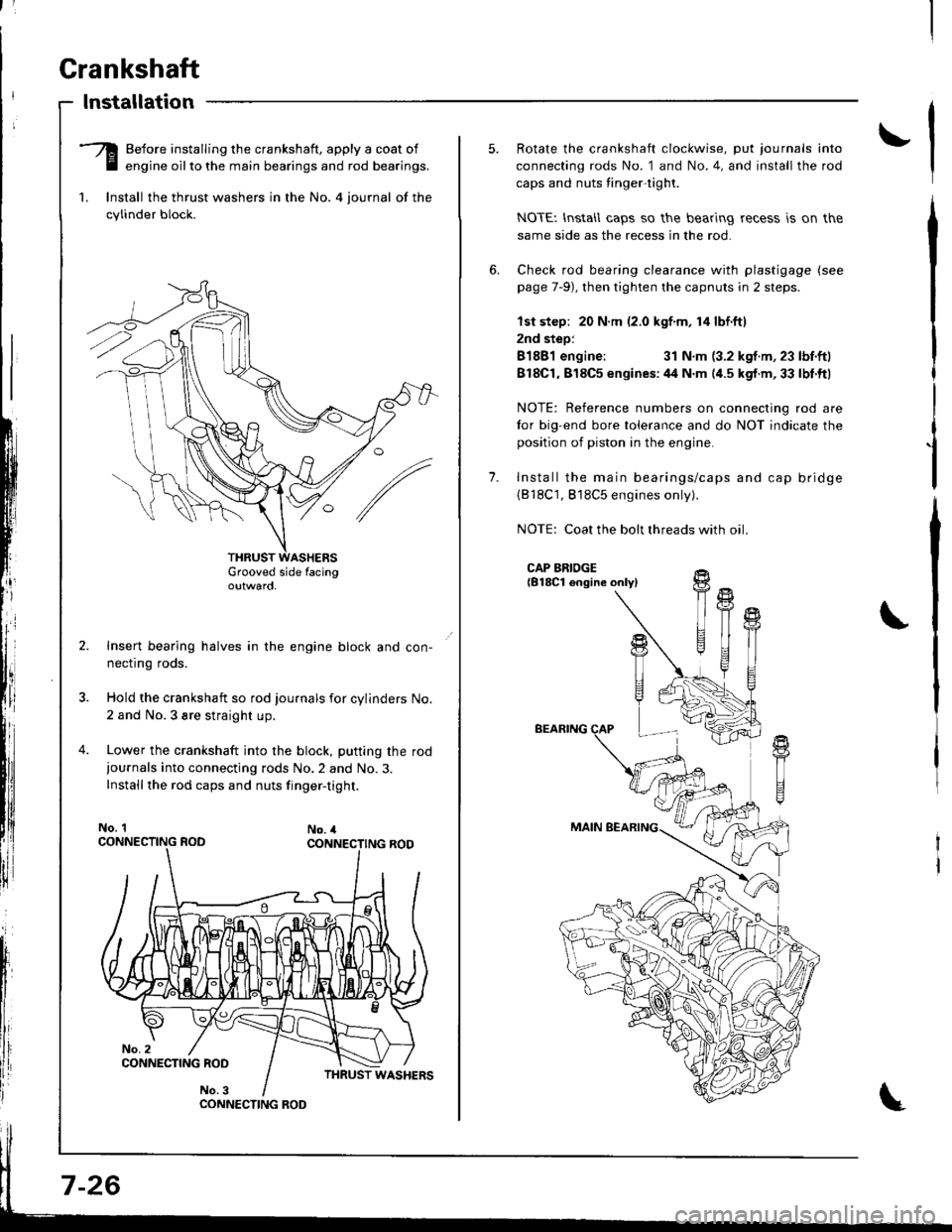
E engine oilto the main bearings and rod bearings.
1. lnstall the thrust washers in the No. 4 iournal of the
cylinder block.
Grooved side facingoutwaro,
Insert bearing halves in the engine block and con-
necflng roos.
Hold the crankshaft so rod journals for cylinders No.
2 and No.3 sre straight up.
Lower the crankshaft into the block, putting the rod
iournals into connecting rods No.2 and No.3.
Installthe rod caps and nuts finger-tight.
No. 1No. 4
CONNECTING ROO
7-26
1.
Rotate the crankshaft clockwise, put journals into
connecting rods No. 1 and No.4, and install the rod
caps and nuts tinger-tight.
NOTEI lnstall caps so the bearing recess is on the
same side as the recess in the rod.
Check rod bearing clearance with plastigage (see
page 7-9), then tighten the capnuts in 2 steps.
lst step: 20 N.m (2.0 kgf m, 14 lbf.ftl
2nd step:
81881 engine:31 N.m (3.2 kgf.m, 23 lbf.ftl
818C1,818C5 enqines:44 N.m (4.5 kgf.m,33 lbt.ftl
NOTE: Reference numbers on connecting rod are
tor big-end bore tolerance and do NOT indicate the
position of piston in the engine.
Install the main bearings/caps and cap bridge(818C1, 818C5 engines only).
NOTE: Coat the bolt threads with oil
CAP BRIDGE{B18Cl engine onlyl
BEARING
MAIN BEARING
fi
U
t{
T
!+
T1
Page 171 of 1681
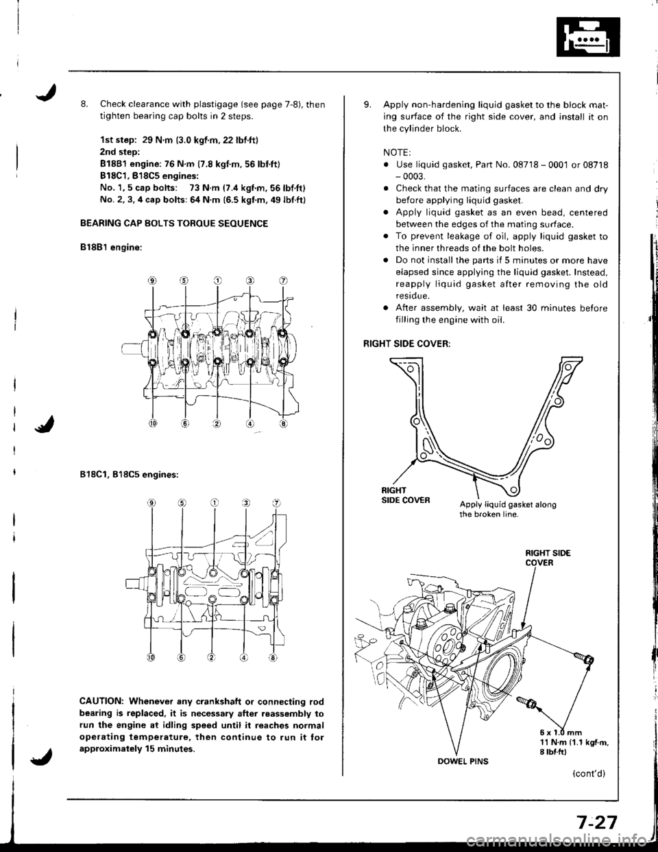
L Check clearance with plastigage (see page 7,8), then
tighten bearing cap bolts in 2 steps.
1st step: 29 N.m (3.0 kgf.m,22 lbf.ft)
2nd step:
81881 engine: 76 N.m 17.8 kgt.m.56 lbnft)
B18C1,818C5 engines:
No. 1,5 cap bolts: 73 N.m (7.4 kgnm,56lbf.ft)
No. 2, 3. 4 cap bolts: 64 N.m (6.5 kgf.m, 49 lbf.ft)
BEARING CAP BOLTS TOROUE SEOUENCE
B lSB'l engine:
818C1, 818C5 engines:
CAUTION: Whenever any crankshaft o. connecting rod
bearing is replaced, it is necessary after reassembly to
run the engine at idling speed until it reaches normal
opelating temperature, then continue to run it tor
approximalely 15 minutes.
Apply non-hardening liquid gasket to the block mat-
ing surface of the right side cover, and install it on
the cylinder block.
NOTEI
. Use liquid gasket, Part No. 08718 - 0001 or 08718- 0003,
. Check that the mating surfaces are clean and dry
before applying liquid gasket.
. Apply liquid gasket as an even bead, centered
between the edges of the mating surface.
. To prevent leakage of oil, apply liquid gasket to
the inner threads of the bolt holes.
. Do not install the parts if 5 minutes or more have
elapsed since applying the liquid gasket. Instead,
reapply liquid gasket after removing the old
residue.
After assembly, wait at least 30 minutes betore
filling the engine with oil.
RIGHT SIDE COVER:
Apply liquid gasket alongthe broken line.
o
a
1l N.m {1.1 kgf.m,I tbf.frl
FIGHT SIDE
(cont'd)
Page 173 of 1681
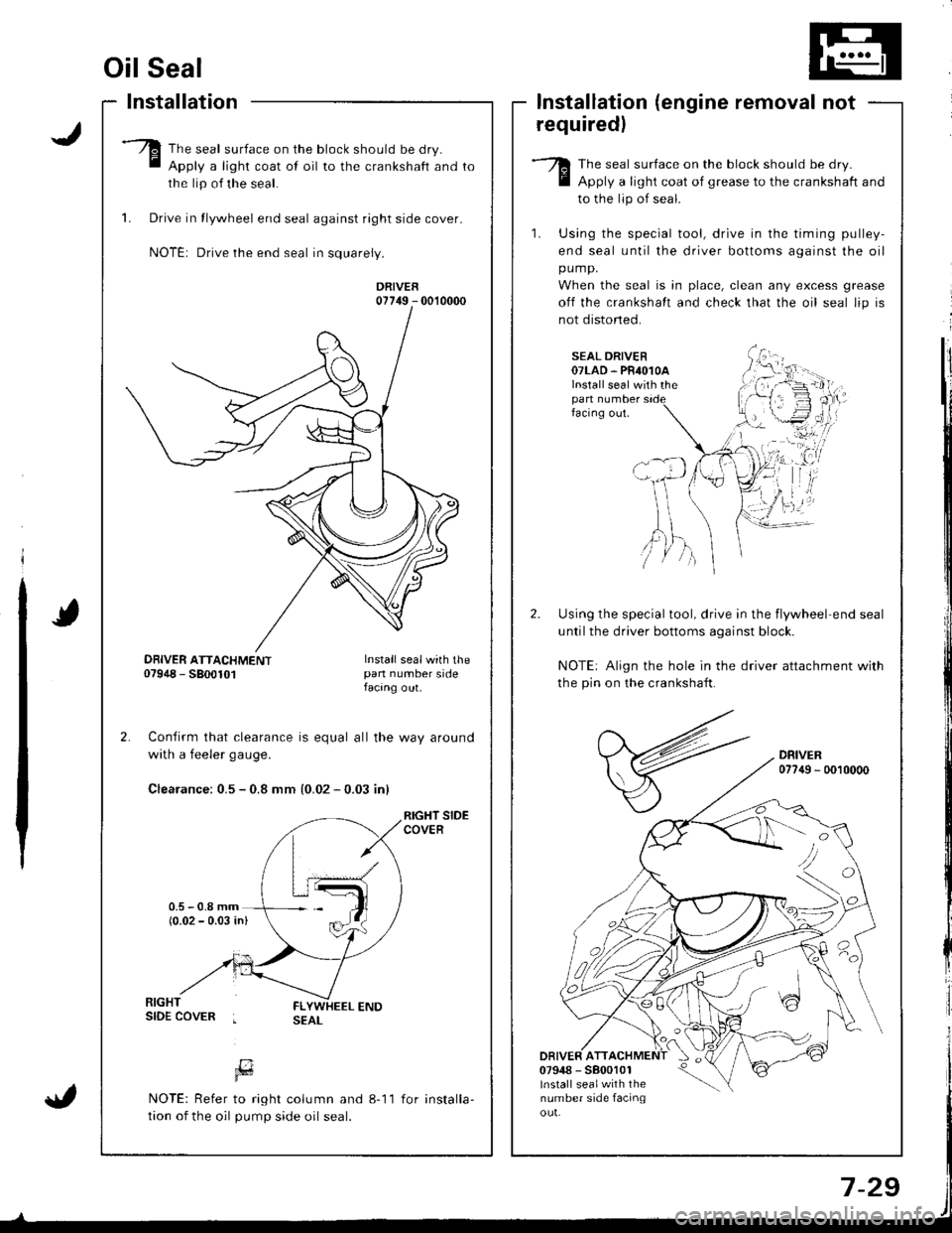
Oil Seal
Installation
The seal surface on the block should be dry.
Apply a light coat of oil to the crankshaft and
the lip of the seal.
1. Drive in tlywheel end seal against right side cover.
NOTE: Drive the end seal in squarely.
DRIVER07749 - 0010000
Confirm that clearance is equal all the way around
with a feeler gaug€.
Clearance: 0.5 - 0.8 mm {0.02 - 0.03 inl
RIGHT SIDECOVER
lnstallation (engine removal not
requiredl
The seal surface on the block should be dry.
Apply a light coat of grease to the crankshaft and
to the lip of seal.
1. Using the special tool, drive in the timing pulley-
end seal until the driver bottoms against the oil
pump.
When the seal is in place, clean any excess grease
off the crankshalt and check that the oil seal lip is
not distoned.
SEAL DRIVER07LAD. PR4O1OAlnstall seal with thepan numberfacing out.
Using the special tool, drive in the flywheel end seal
untilthe driver bottoms aqainst block.
NOTE: Align the hole in the driver attachment with
the pin on the crankshaft.
DRIVER077{9 - 0010000
DRIVER ATT07948 - 5800101lnstall sealwith thenumber side facinqou!.
'tvA,)/ )
DBIVER ATTACHMENT07948 - 5800101Install sealwith thepan number sidefacang out.
[7Fd
NOTE: Refer to right column and 8-11
tion of the oil pump side oil seal.
for installa-
Page 180 of 1681
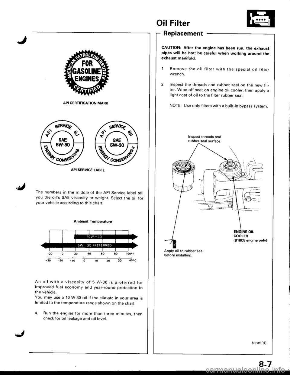
Oil Filter
Replacement
CAUTION: After the engine has been run, the exhaustpipes will be hot; be careful when working around theexhaust manitold.
Re m ove the
wrench.
Iilter with the speciallilter
API CERTIFICATION MARK
API SERVICE LABEL
The numbers in the middle of the Apl Service tabelyou the oil's SAE viscosity or weight. Selecr rhe oilyour vehicle according to this chart:
Inspect the threads and rubber seal on the new fil-ter. Wipe oif seat on engine oil cooler, then apply alight coat ol oil to the filter rubber seal.
NOTE: Use only filters with a built-in bypass system.
Inspect threads andrubber seal surface.
tell
for
Ambi€nt Temperature
An oil with a viscosity of 5 W 30 is preferred forimproved fuel economy and year-round protection inthe vehicle.
You may use a 10 W 30 oil if the climate in your area islimited to the temperature range shown on the chart.
4. Run the engine for more than three minutes, thencheck for oil leakage and oil level.
Apply oilto.ubber sealbefore installing.-to20-30
{cont'd)
8-7
Page 181 of 1681
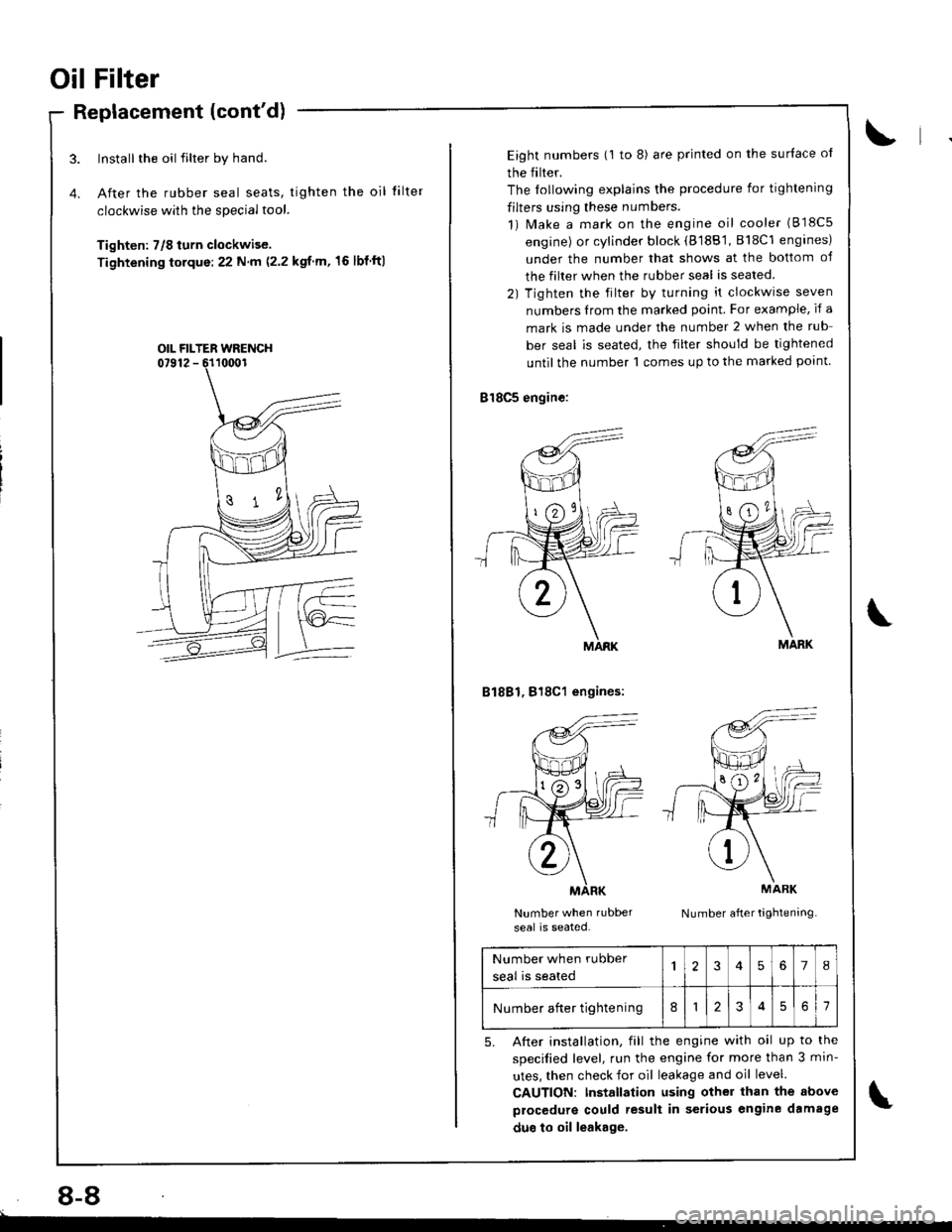
Oil Filter
Replacement (cont'd)
Install the oil filter by hand.
After the rubber seal seats, tighten the oil
clockwise with the special tool.
Tighten: 7/8 turn clockwise.
Tightening torque:22 N m (2.2 kgf m,'16 lbf ftl
tilte r
OIL FILTER WRENCH
8-8
Eight numbers (1 to 8) are printed on the surlace ol
the filter.
The lollowing explains the procedure for tightening
filters using these numbers.
1) Make a mark on the engine oil cooler (818c5
engine) or cylinder block (8188'1, 818C1 engines)
under the number that shows at the bottom of
the filter when the rubber seal is seated.
2) Tighten the filter by turning it clockwise seven
numbers Irom the marked point. For example, if a
mark is made under the number 2 when the rub
ber seal is seated, the filter should be tightened
until the number 1 comes up to the marked point
818C5 engine:
B1881, 818C1 engines:
Number when rubber
seal is seated.Number after tightening
MARK
MARK
Number when rubber
seal is seated
'I2345678
Number after tightening812561
5. After installation, fill the engine with oil up to the
specilied level, run the engine for more than 3 min-
utes, then check for oil leakage and oil level.
CAUTION: Installation using other than the above
procedure could result in serious engine damage
duo to oil leakage.
Page 182 of 1681
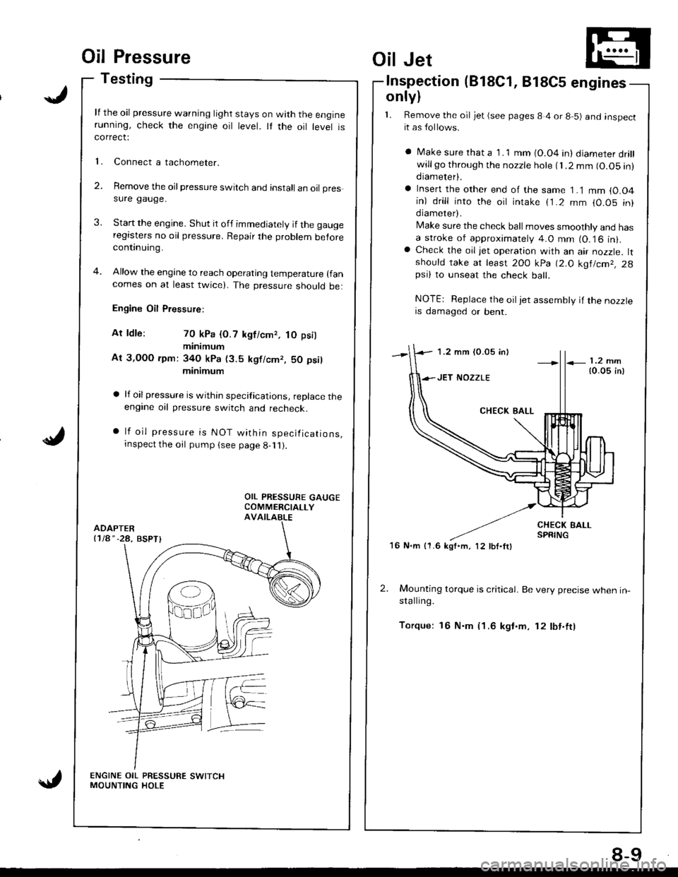
Oil Pressure
Testing
lf the oil pressure warning light stays on with the enginerunning, check the engine oil level. It the oil level iscorrect:
Connect a tachometer.
Remove the oil pressure switch and install an oil pressure gauge.
Start the engine. Shut it off immediately if the gaugeregasters no oil pressure. Repair the problem beforecontinuing.
Allow the engine to reach operating temperature (fan
comes on at least twicel. The pressure should be:
Engine Oil Pressure:
At ldle: 70 kPa {O.7 kgficmr, tO psil
minimum
At 3,OOO rpm: 34O kPa (3.5 kgf/cmr, 50 psil
minimum
a lf oilpressure is within specifications, replace theengine oil pressure switch and recheck.
a lf oil pressure is NOT within specifications,rnspect the oil pump (see page g-11).
l�
2.
Oil Jet
lnspection(818C1, 818C5 engines
only)
1. Remove the oil jet (see pages 8 4 or 8 5) and inspectit as follows.
a Make sure rhat a 1 .1 mm (O.04 in) diameter drillwillgo through the nozzle hole fl.2 mm (O.O5 in)diameter).
a Insert the other end of the same 1 .1 mm {0.O4in) drill into the oit intake (1.2 mm (0.05 in)diameter).
Make sure the check ball moves smoothly and hasa stroke of approximately 4.0 mm (O.16 in).a Check the oil jet operation with an air nozzle. ltshould take at least 2OO kPa 12.O kg|lcm2, 2gpsi) to unseat the check ball.
NOTE: Replace the oiljet assembly if the nozzleis damaged or bent.
2. Mounting torque is critical. Be very precise when in-stalling.
Torque: 16 N.m (1.6 kgf.m, 12 lbf.ftl
1.2 mm (0.05 inl
16 N.m {1.6 kgf'm, 12 lbf.ftl
8-9
Page 184 of 1681
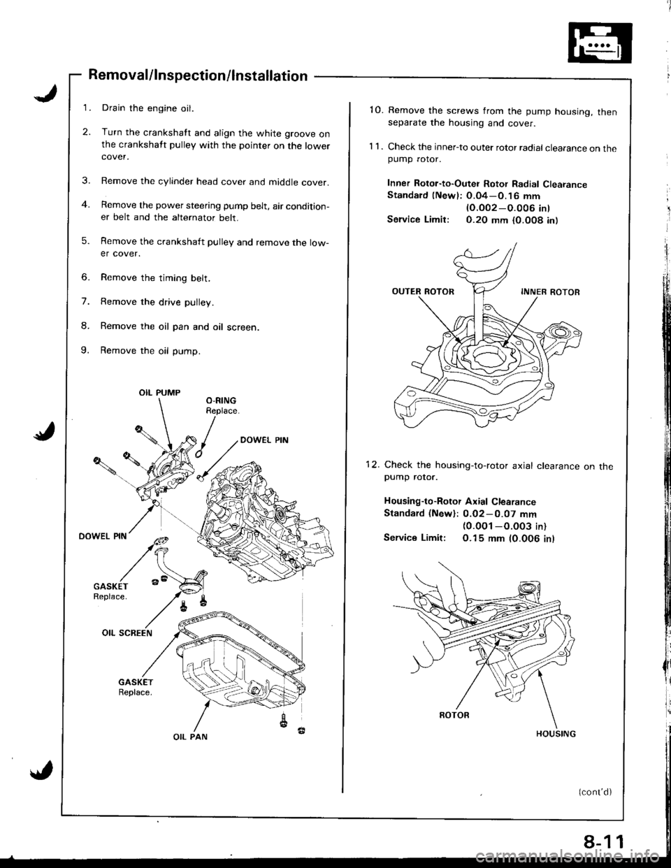
3.
Removal/lnspection/lnstallation
Drain the engine oil.
Turn the crankshatt and align the white groove onthe crankshatt pulley with the pointer on the lowercover.
Remove the cylinder head cover and middle cover.
Remove the power steering pump belt, air condition-er belt and the alternator belt.
Remove the crankshaft pulley and remove the low-er cover.
6. Remove the timing belt,
7. Remove the drive pulley.
8. Remove the oil pan and oil screen.
9. Remove the oil pump.
OIL PUMP
OIL PAN
8-1
'10. Remove the screws from the pump housing, thenseparate the housing and cover.
1 1 . Check the inner-to outer rotor radial clearance on thepumD rotor.
Inner Rotor-to-Outei Rotor Radial ClearanceStandard (Newl: O.04-O.16 mm
lO.OO2-O.O06 int
Service Limir: 0.20 mm {0.O08 in)
12. Check the housing-to-rotor axial clearancepump rotor.
Housing-to-Rotor Axial Clearance
Standard (New): 0.02-0.07 mm(0.0O1 -O.003 in)
Service Limit: O.15 mm (0.006 inl
on tne
1