check engine HONDA INTEGRA 1998 4.G Repair Manual
[x] Cancel search | Manufacturer: HONDA, Model Year: 1998, Model line: INTEGRA, Model: HONDA INTEGRA 1998 4.GPages: 1681, PDF Size: 54.22 MB
Page 276 of 1681
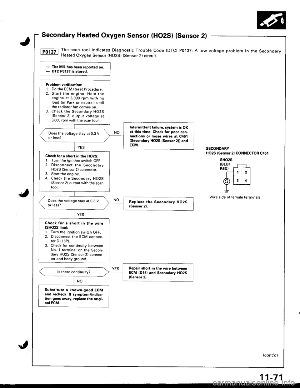
Secondary Heated Oxygen Sensor (HO2S) {sensor 2l
The scan tool indicates Diagnostic Trouble Code (DTC) P0137: A low voltage problem in the SecondaryHeated Oxygen Sensor (H02S) (Sensor 2) circuit.
(cont'd)
The MIL ha3 been reDorted on.DTC P0137 is storod.
Problem veritication:1. Do the ECM Reset Procedure.2. Start the engine. Hold theengine at 3,000 rpm with noload (in Park or neutral) untilthe radiator fan comes on,3. Check the Secondary H02S(Sensor 2) output voltage at3,000 rpm with the scan 1ool.
Inte.mittent failure, system is OKat lhb time. Ch6ck Ior ooor con-nections or loose wires at C451lSeconddry HO2S {Sensor 2)l andECM.
Does the voltage stay at 0.3 Vor less?
Check for a short in th€ HO2S:1. Turn the ignition switch OFF.2. Discon nect the SecondaryHO2S (Sensor 2) connector.3. Start the engine.4. Check the Secondary H02S(Sensor 2) output whh the scantool.
Does the voltage stay at 0.3 Vor less?
Check tor a short in the wire{SHO2S line):r. I urn rne rgnt on swttch uFF,2. Disconnect the ECM connec,tor D 116P).3. Check for continuity betweenNo. '1 terminal on the Secon-dary HO2S {Sensor 2) connector and body ground.
Ropair short in tho wira bctweenECM (D14) and Secondrry HO2S{Senso.2).
ls there continuity?
Substitute a known-good ECMand recheck. It symptom/indice-taon goes away, replace the origi-nel ECM.
SECONDARYHO2S (Sensor 2l CONNECTOR C451
sHo2sIBLU/REDI f- --
T-l 1 2ltr11(Or ls rl
L
Wire side oI fernale terminals
11-71
Page 277 of 1681
PGM-FI System
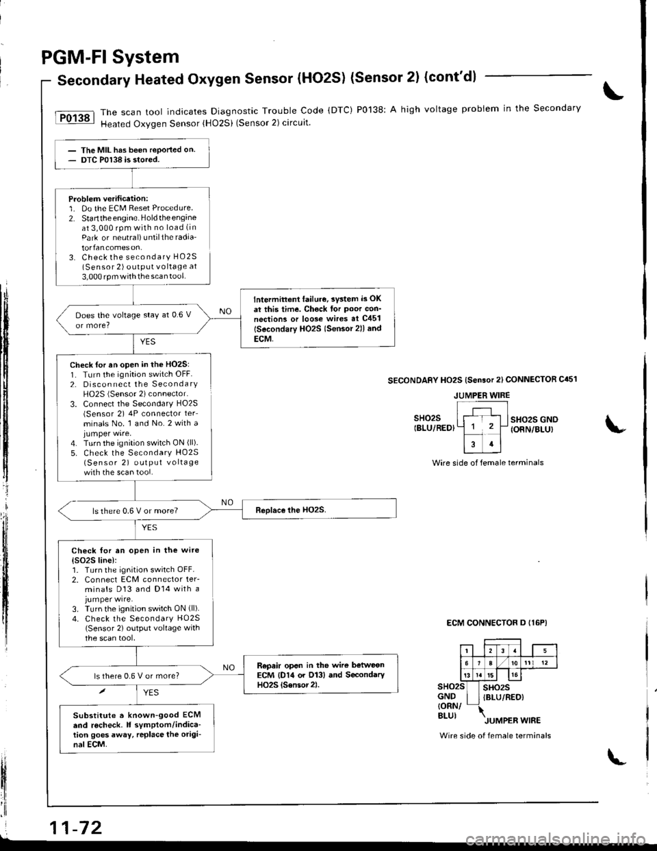
Secondary Heated Oxygen Sensor (HO2S) (Sensor 2l (cont'd)
The scan tool indicates Diagnostic Trouble Code (DTC) P0138: A high voltage probiem in the Secondary
Heated Oxygen Sensor {HO2Si (Sensor 2) circuit.
YES
The MIL has been reported on.DTC P0138 is stored.
Problem verification:1. Do the ECM Reset Procedure2. Startthe engine. Holdtheengineat 3,000 rpm with no load (in
Park or neutral) untilthe radia'
torfancomeson.3. Check the secondary HO2S(Sensor 2) outPUt vo ltage at
3,000 rpm withthe scan tool.
lntermittent lailur€, svsted i3 OK
at this time. Chock tor Poor con'
nections or loo3e wires at C451
lSecondary HO2s lsensor 2ll and
ECM,
Does the voltage stay at 0.6 V
ls there 0.6 V or more?
Check for an open in the wite
{s()2S line):1. Turn the ignition switch OFF.2. Connect ECM connector ter-minals D13 and Dl4 with ajumper wire.3. Turn the ignition switch ON (ll).
4. Check the Secondary HO25(Sensor 2) output voltage withthe scan tool,
Repair opsn in the wire b€tweonECM {D14 or O13} and SecondaryHO2S {Sensor2).ls there 0,6 V or more?
Substitute a known-good ECMend r6check. It symptom/indica-tion goes away, rcplace the origi-nal ECM.
tI
t$
ffi
tljl'l
t,
lfi
il
fl'I
Check for an open in the HO2S:1. TLrrn the ignition switch OFF.2. Disconnect the SecondaryH02S (Sensor 2) connector.
3. Connect the Secondary HO2S(Sensor 2) 4P connector ter_
minals No. 1 and No.2 with ajumper wire.4. Turn the ignition switch ON (ll).
5. Check the Secondary HO25(Sensor 2) output vo lta ge
with the scan tool.
SECONDAFY HO2S {Sensor 2l CONNECTOR C451
sHo2sIBLU/REDIsHo2s GNOIONN/BLUI
Wire side of female terminals
ECM CONNECTOR D I16P}
sHo2sGND{ORN/BLUI
sHo2sIBLU/RED)
Wire side of female terminals
JUMPER WIRE
i 11-72L
Page 278 of 1681
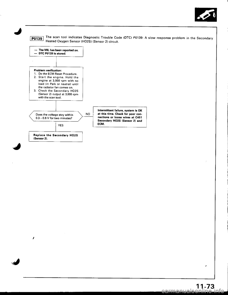
The scan tool indicates Diagnostic Trouble Code (DTC) P0139: A slow response problem in the SeconoarvHeated Oxygen Sensor (H02S) (Sensor 2) circuit.
The MIL has boen reDorted on.DTC P0139 b sto.od.
P.oblem ve tication:1. Do the ECM Reset Procedure.2. Start the engine. Hotd theengine at 3,000 rpm with noload (in Park or neutral) untilthe radiator fan comes on,3. Check the Secondary HO2S{Sensor 2) output ar 3,000 rpmth the scan tool.
Intarmittert lailurg, systsm i! OKat thi! time. Chsck for Door con-nections o. loose wi.es at C451Secondary HO2S lsonsor 2) .ndECM.
Does the voltage stay within0.3 - 0.6 V tortwo minutos?
Page 279 of 1681
PGM-FI System
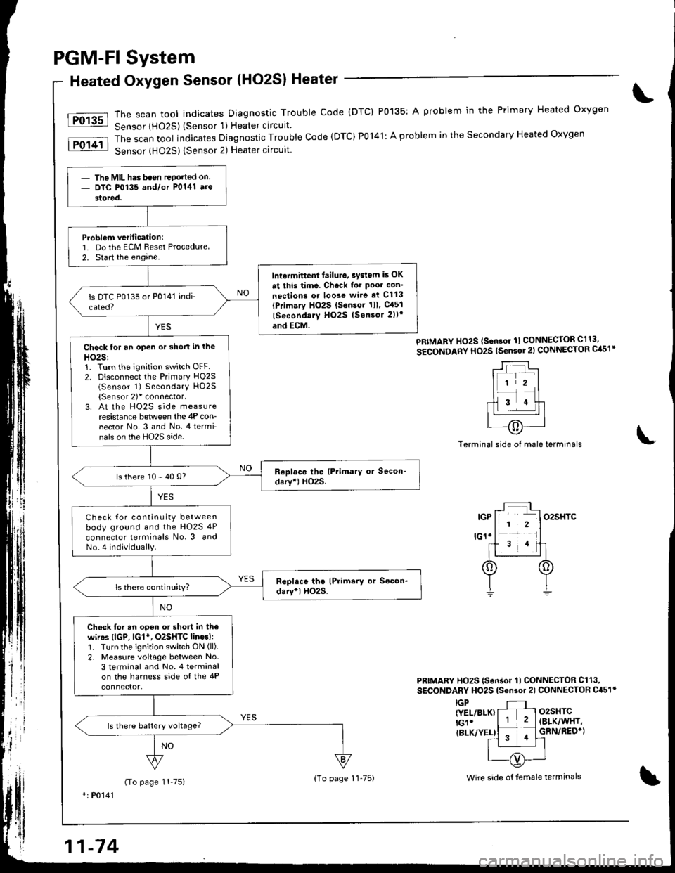
Heated Oxygen Sensor (HO2S) Heater
The scan tool indicates Diagnostic Trouble code (DTC) P0135: A problem in the Primary Heated oxygen
Sensor lHO2S) (Sensor 'l) Heater circuit
The scan tool indicates Diagnostic Trouble Code (DTC)P0141: A problem in the Secondary Heated Oxygen
Sensor {HO25) {Sensor 2) Heater circuit
Fo13sl
lFol4il
PRIMARY Ho2S (sen3or 1) CONNECToR C113,
SECONDARY HO2S (sensor 2l CONNECTOR Cil51'
Terminal side of male terminals
PRIMARY HO2S (SonSor 1l CONNECTOR Cl13,
SECONDARY HO2S lsan3or 2) CONNECTOR C451r
o2sHTC(BLK/WHT,
GRN/REO'}
IGP{YEL/BLK}lGlr(BLK/YEL)
(To page 11-75)*: P0141
- The MIL has been rePorted on- DTC P0135 and/or P0141 ate
stored.
Probl€m verilication:1. Do the ECM Reset Procedure
2. Start the engine.
lnt€rmitlent failure. 3vslem is OK
at this time. Check for Poo. con'
noction3 o. loose wire ai Cl13(Primary HO2S (S.nsor 1ll. gl51
lSocondary H02S lSensor 2))'
and ECM.
Check for an open or short in tho
HO2S:1. Turn the ignition switch OFF.2. Disconnect the Primary HO2S(Sensor 1) Secondary HO2S
{Sensor 2)'connector,3. At the HO2S side measureresistance between the 4P con-nector No. 3 and No. 4 terminals on the HO2S side.
ls there 10 - 40 0?
Check Ior continuity betweenbody ground and the HO2S 4P
connector lerminals No. 3 andNo.4 individually.
ls there continuity?
Ch€ck for an open or short in thewir63 (lGP, lG1*, O2SHTC lines):1. Turn the ignition switch ON (ll).
2. Measure voltage between No.3 terminal and No. 4 terminalon the harness side of the 4P
ls there batlery vohage?
{1o page 1l-75)Wire side of female terminals
Page 282 of 1681
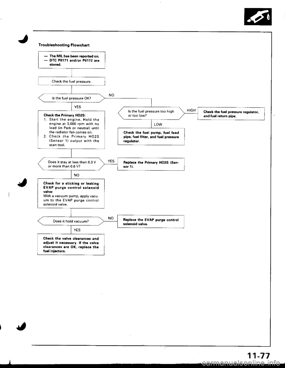
Troubleshooting Flowchart
HIGH
- The MIL ha3 been rcoortod on.- OTC P0171 andlor PO'l72.re3tored.
ls the Iuel pressure OK?
ls the fuel pressure too highChock th€ luel p.essure regulator,and tu€l return pipe.Ch€ck the Primary HO2S:1. Start the engine. Hold theengine at 3,000 rpm with noload (in Park or neutral) untilthe radiator lan comes on.2. Check the Primary HO2S{Sensor 1) output with thescan tool.
Chock the tuel pump, fuel feodpipe, fuol fiher, and tuol prcssureregulator.
Does it stay at less than 0.3 Vor more than 0.6 V?Rapl.ce the Primary HO2S {Sen-3or ll.
Check lor a sticking or l€akingEVAP purge control solenoid
With a vacuum pump, apply vacu,um to the EVAP purge controlsolenoid valve.
Does it hold vacuum?
Chock the valvc cl6a.ance3 andadjust it nocessary. lf th. valvocloarance3 are OK, reDlaco thGtuel ini€cto6.
11-77
Page 285 of 1681
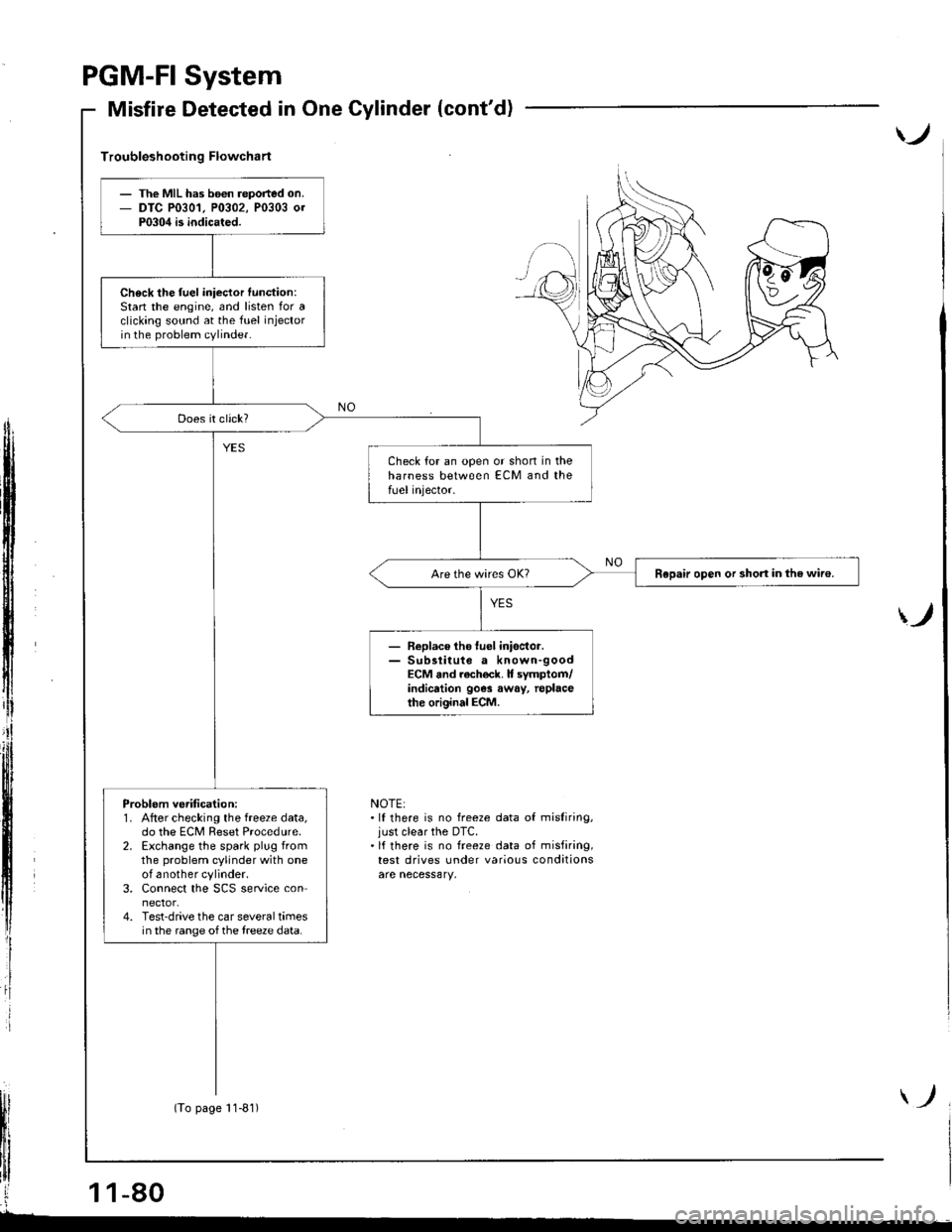
PGM.FI
Misfire
System
Detected in One Cylinder (cont'd)
)
Troubleshooting Flowchart
ff
i
)
NOTE:.lf there is no freeze data of misliring,just clear the DTC.'lf there is no freeze data of misfiring,test drives under various conditions
The MIL has b6€n reported on.DTC P0301, P0302, P0303 0rP0304 is indicated.
Check the fuel iniector function:Stan the engine, and listen for aclicking sound at the fuel injectorin the problem cylinder.
Check for an open or shon in theharness between ECM and thefUel injector.
Repair open or short in the wiro.
- Replace tho luel inisctor.- Sub3titute a known-goodECM and rach€ck. It symptom/indicrtion 90e3 away, replacethe original ECM.
Problem ve.ification:1. After checking the freeze data,do the ECM Reset Procedure.2. Exchange the spark plug fromthe problem cylinder with oneof another cylinder.3. Connect the SCS service connector.4. Test-drive the car several timesin the range of the treeze data.
(To page 11-81)
Page 286 of 1681
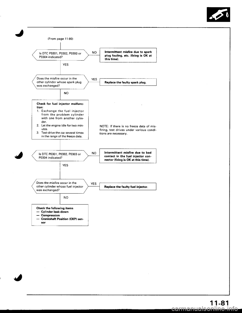
(From page l1-80)
Iniermittenl misfire due lo sparkplug fouling, otc. Iti.ing is OK atthis timo).
Does the misfire occur in theother cylinder whose spark plugwas exchanged?Replace the faultv spark plug.
Check for tuel ini€ctor maltunc-taon:1. Exchange the fuel injectorfrom the problem cylinderwith one from another cylin'der.2. Let the engine idle lortwo min-uteS.3. Test-drive the car sevoraltimesin the range ofthe treeze data.
Int€rmitt€nt mislire due to badcontact in tho tuel iniector con-nector lfiring is OK at thb time).
Does the misfire occur in theother cylinder whose tuel injectorwas exchanged?Replace the laultv tuel iniector.
Check the following items- Cylinde. lerk-down- Compaession- Crankshafl Position (GKPI son-
NOTE: lf there is no freeze data of misfirang, test drives under various condi-trons are necessary.
1 1-81
Page 287 of 1681
I
PGM-FI System
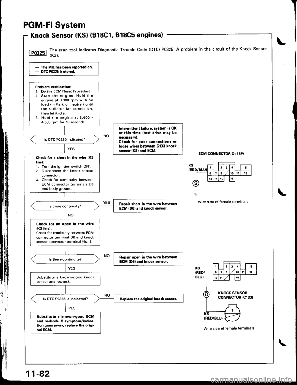
Knock Sensor {KSl (B18C1, 818C5 enginesl
The scan tool indicates Diagnostic Trouble Code (DTC) P0325: A problem in the circuit of the Knock Sensor
{KS).
ECM CONNECIOR D I16P)
Wire side of female terminals
- Tho MIL he3 b6en.eportgd on.- DTC P0325 i3 3tor6d,
Probl6m veriticalion:1. Do the ECM Reset Proc€dure.2. Start the engine. Hold theengine at 3,000 rpm with noload {in Park or neutral} untilthe radiator lan comes on,then let it idle.3. Hold the engine at 3,000 -
4,000 rpm for 10 seconds.
Intarmitt.nl failurc, ay3tem i3 OKrt thii timc llest driva mav b.naccrsrryl.Chcck for poor connactions o.loos. wir.. botw..n Cl33 knocks.nlor (KSl rnd EcM.
Ch6ck {or a 3hort in tho wirc IKSlin6l:1. Turn the ignition switch OFF.2. Disconnect the knock sensorconnector,3. Check for continuity betweenECM connector terminals D6and body ground.
R.o.i. short in thG wire batwaanECM lD6l rnd knock..n3or.
Check for an opcn in lho wiro
IKS lin.l:Check for continuity between ECMconnector terminal D6 and knocksensor connector terminal No. 1.
Reprir op.n in tho wira bttw..nECM lD6l and knock ..Nor.
Substitute a known-good knocksensor and recheck.
Raplac6 thc odginrl knock sanror.ls DTC P0325 is indicated?
Substitut6 . known-good ECM.nd rocheck. lf aymptom/indic.-tion 9003 away, .opbcc thc origi-nal ECM.Wire side of female terminals
Page 293 of 1681
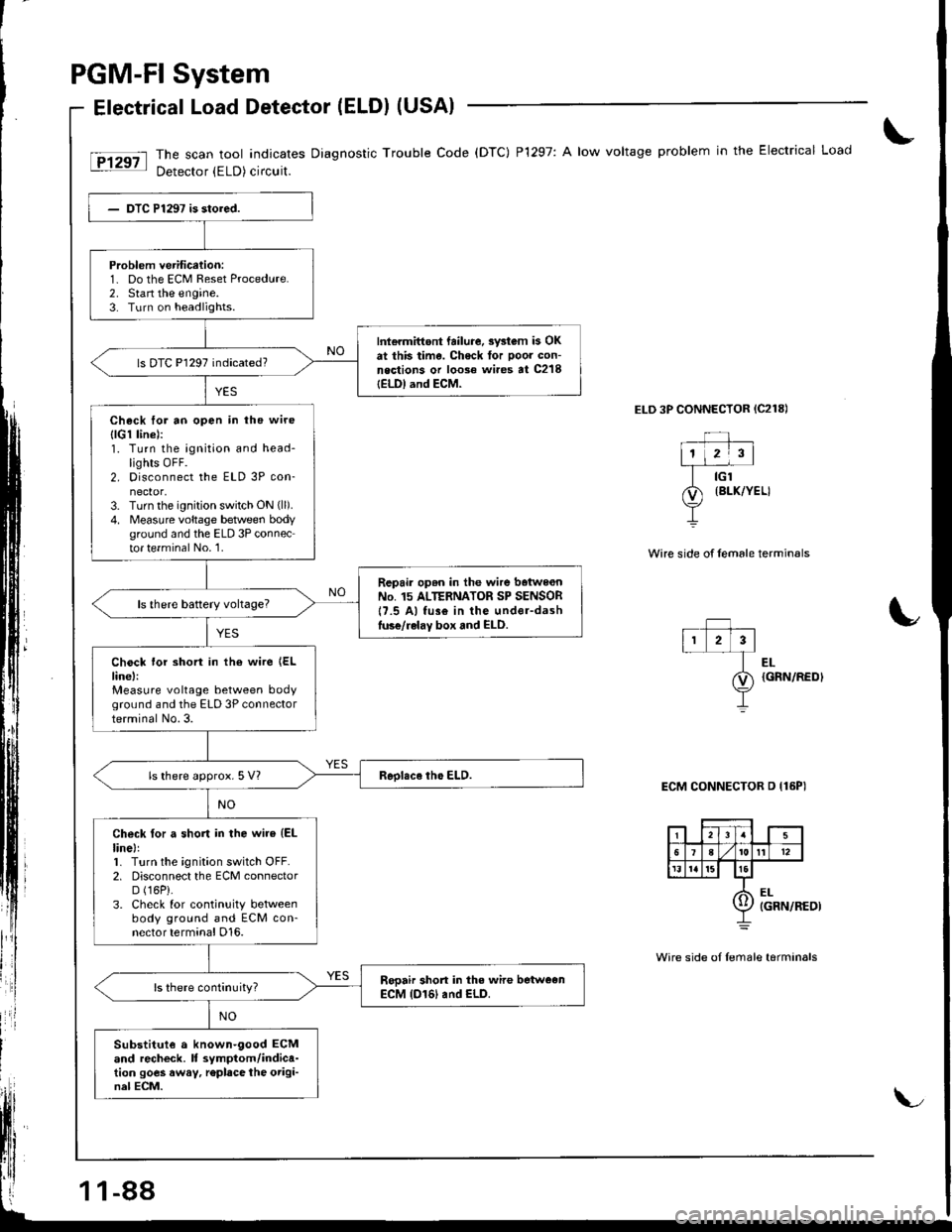
PGM-FI System
Electrical Load Detector (ELDI (USAI
The scan tool indicates Diagnostic Trouble Code (DTC) P1297: A low voltage problem in the Electrical Load
Detector (ELD) circuit.
ELD 3P CONNECTOR {C218)
Wire side of female termin€ls
Problem verification:1- Do the ECM Reset Procedure.2. Stan the engine.3. Turn on headlights.
Int€rmittont failure. swtom b OKat this time. Check tor poor con-neqtions or loose wi.es at C218IELDI and ECM-
ls DTC P1297 indicated?
Check for ao open in the wire
{lG1 linel:1. Turn the ignition and head-lights OFF.2. Disconnect the ELD 3P con-nector,3. Turn the ignition switch ON (ll).
4. Measure voltage betlveen bodyground and the ELD 3P connector te.minal No.'1.
Repair op6n in the wire baiwe€nNo. 15 ALTERNATOR SP SENSOR17.5 Al fus€ in the under-dashluse/relay box and ELD.
Chock lor short in the wire {ELline,:Measure voltage between bodyground and the ELD 3P connectorterminal No.3.
ls there approx. 5 Vl
Check for a short in the wire (EL
linel:1. Turn the ignition switch OFF.2. Disconnect the ECM connectorD (16P).
3. Check for continuity betweenbody ground and ECM con-nector terminal D16.
Sooair short in the wire betweenECM (D161 and ELD.
Substitut€ a known-9ood ECMand recheck. It symptom/indica-tion goes away, r€place the origi-nal ECM.
EL{GRN/REDI
ECM CONNECTOR D {16PI
Wire side oI Iemale tarminals
11-88
Page 294 of 1681
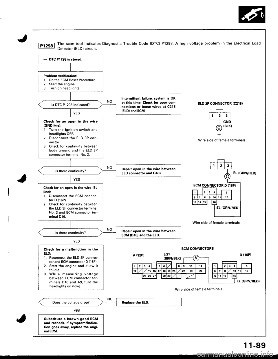
The scan tool indicates Diagnostic Trouble Code (DTC) P1298: A high voltage problem in the Electrical Load
Detector (ELD) circuit.
ELD 3P CONNECTOR {C218}
_rJ ,112 3l-f-dnD
Wire side of female terminals
ECM CONNECTORS
{BLKI
Wire side of female termin6ls
EL {GRN/REDI
ECM CONNECTOR D (16PI
P.oblem verification:l� Do the ECM Reset Procedure.2. Start the engine.3. Turn on headlights.
lntermittent failure, 3vstem is OKel ihis time. Chock for ooor con-nections or loose wiros at C218(EtD) and ECM.
ls DTC P1298 indicated?
Check lor an open in the wire(GNO linel:1. Turn the ignition switch andheadlights OFF.2. Disconnect the ELD 3P con-nector.3. Check for continuity betweenbody ground and the ELD 3Pconnector terminal No. 2.
Bepair opon in the wire bstweenELO connector and G402.
Check tor an opon in the wire IELlinell1. Disconnect the ECM connec-tor D (l6Pi.
2. Check for continuity betweenthe ELD 3P connector terminalNo. 3 and ECM connector terminal D16.
Repair open in the wir€ betweenECM l016l and rhe ELD.ls there continuity?
Check for a malfunction in theELD:1. Reconnect the ELD 3P connec-tor and ECM connector D (16P).
2. Start the engine and allow itto idle.3. Wh ile measuring voltagebetween ECM connector terminals D16 and A9, turn theheadlights on {low).
Sub3titute a knownjgood ECMand rechock. lf 3vmptom/indics-tion 9oe6 away, replace the original ECM.
A l32PtIBRN/BI-KI
Wire side of female ierminals
1 1-89