check engine HONDA INTEGRA 1998 4.G Owner's Guide
[x] Cancel search | Manufacturer: HONDA, Model Year: 1998, Model line: INTEGRA, Model: HONDA INTEGRA 1998 4.GPages: 1681, PDF Size: 54.22 MB
Page 214 of 1681
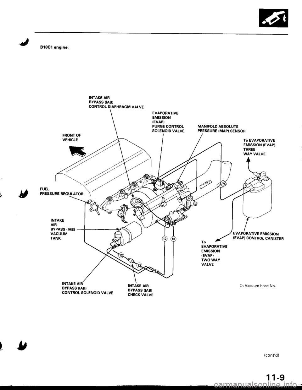
B18C1 engine:
EVAPORATIVEEMtSStONIEVAPIPURGE CONTROLSOLENOID VALVEMANIFOLD ABSOLUTEPRESSURE {MAP) SENSOBFRONT OFVEHICLE
INTAKEAIREYPASS IIAB)VACUUMTANK
To EVAPORATIVEEMISSION {EVAP)THREEWAY VALVE
O: Vacuum hose No,
EVAPORATIVE EMISSIONIEVAPI CONTROL CANISTER
EVAPORATIVEEMtSSION{EVAP}TWO WAYVALVE
INTAKEBYPASS (IABI
CONTROL SOLENOID VALVE
INTAKE AIRBYPASS {IABICHECK VALVE
{cont'd)
1 1-9
Page 217 of 1681
![HONDA INTEGRA 1998 4.G Owners Guide System Description
Vacuum Connections (contdl
Bl8Cl engine:
rl
llj
lli;r
Fil
ryl
xr
flti
li
tl
I
lr; I
,l{9^h;L-r
-1] PRIMARY HEATED OXYGEN SENSOR IPRIMARY HO2SItsENsoR 1l
O SECONDARY HEATED OXYGE HONDA INTEGRA 1998 4.G Owners Guide System Description
Vacuum Connections (contdl
Bl8Cl engine:
rl
llj
lli;r
Fil
ryl
xr
flti
li
tl
I
lr; I
,l{9^h;L-r
-1] PRIMARY HEATED OXYGEN SENSOR IPRIMARY HO2SItsENsoR 1l
O SECONDARY HEATED OXYGE](/img/13/6069/w960_6069-216.png)
System Description
Vacuum Connections (cont'dl
Bl8Cl engine:
rl
llj
lli;r
Fil
ryl
xr
flti
li
tl
I
lr; I
,l'{9^h;'L-r
'-1] PRIMARY HEATED OXYGEN SENSOR IPRIMARY HO2SItsENsoR 1l
O SECONDARY HEATED OXYGEN SENSOR (SECONDARY
HO2SI ISENSOR 2)
.3) MANIFOLD ABSOLUTE PRESSUBE {MAPI SENSORii ENGINE COOLANT TEMPERATURE (ECT} SENSORii INTAKE AIR TEMPERATURE IIAT) SENSORi6-- CRANKSHAFT SPEEO FLUCTUATION ICKF} SENSOR
a7) KNocK sENsoR lKslO IDLE AIR CONTROL IIAC) VALVE
i' FUEL INJECTOR
@ FUEL FILTER
O FUEL PRESSURE REGULATOR
[4 FUEL PUMP {FP}@ FUEL TANKI.13 FUEL TANK EVAPORATIVE EMISSION (EVAP) VALVE
.19 FUEL PULSATION DAMPER{!9 AIR CLEANER
O RESONATOR
I t-az
I: Vacuum hose No.
iio INTAKE AIR BYPASS IIAE) CONTROL DIAPHRAGM VALVE(!9) INTAKE AIR BYPASS {IABI CONTROL SOLENOID VALVE
6I INTAKE AIR BYPASS (IAB) VACUUM TANK
CI INTAKE AIR BYPASS {IABI CHECK VALVE
€9 THREE WAY CATALYTIC CONVEFTER (TWC)
2jI POSITIVE CRANKCASE VENTILATION (PCV} VALVE
€! EVAPORATIVE EMISSION (EVAPI CONTROL CANISTER
?9 EVAPORATIVE EMISSION {€VAPI PURGE CONTNOLSOLENOID VALVE0d EVAPORATIVE EMISSION (EVAP}TWO WAY VALVE
iii) EVAPORANVE EMISSION {EVAP) BYPASS SOLENOID VALVE,3 EVAPORAIVE EMTSSTON {EVAP} CONTROL CANISTER VENTSHUT VALVE?9 FUEL TANK PRESSUR€ SENSORi3O] EVAPORATIVE EMISSION IEVAP} THREE WAY VALVE
Page 237 of 1681
t-
il
Troubleshooting ".
Troubleshooting Proccdures
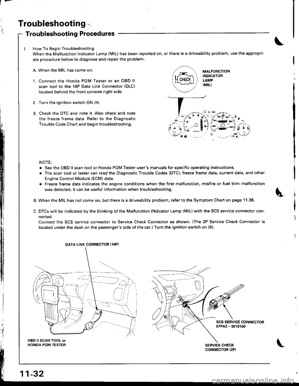
How To Begin Troubleshooting
When the Malfunction lndicator Lamp {MlL) has been reponed on, or there is a driveability problem, use the appropri-
ate procedure below to diagnose and repair the problem.
A. When the MIL has come on:
'1. Connect the Honda PGM Tester or an OBD ll
scan tool to the 16P Data Link Connector (DLC)
located behind the front console right side.
2. Turn the ignition switch ON (ll).
3. Check the DTC and note it. Also check and note
the freeze frame data. Refer to the Diagnostic
Trouble Code Chart and begin troubleshooting.
NOTE:
. SeetheOBDll scantool or Honda PGM Tester user's manuals for specific operating instructions.
. The scan tool or tester can read the Diagnostic Trouble Codes (OTC). freeze frame data, current data, and other
Engine Control Module (ECM) data.
. Freeze frame data indicates the engine conditions when the first malfunction, misfire or luel trim malfunction
was detected. lt can be useful information when troubleshooting.
B. When the MIL has not come on, but there is a driveability problem, refer to the Symptom Chart on page 11-36.
C. DTCS wjll be indicated by the blinking of the Malfunction lNdicator Lamp {MlL) with the SCS service connector con-
nected.
Connect the SCS service connector to Service Check Connector as shown. (The 2P Service Check Connector is
located under the dash on the passenger's side of the car,) Turn the ignition switch on (lll.
scs sERvlcE coNNEcToEo?PAZ - 0010100
MAI-FUNCTIONINDICATORLAMP{MIL)
DATA LINK CONNECTOR Il6PI
OBO ll SCAN TOOL orHONDA PGM TESTER
Page 245 of 1681
I
t
h,,l,!
il
Troubleshooting
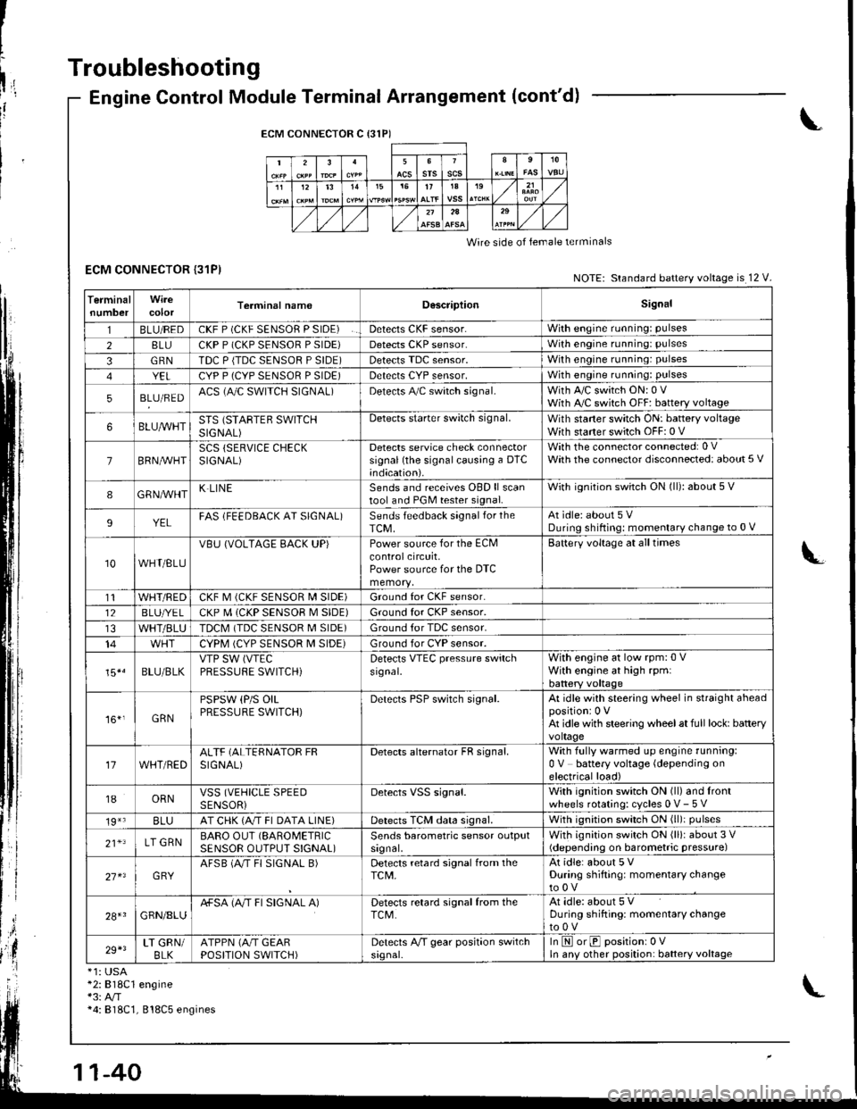
ECM CONNECTOR {31P)
Engine Control Module Terminal Arrangement (cont'd)
ECM CONNECTOR C {31P)
235srsscs1112t31515t71A19
2A
Wire side of lemale terminals
NOTE: Standard battery voltage is 12 V.
TerminalnumbercolorTerminal namoD6scriptionSignal
1BLU/REDCKF P (CKF SENSOR P SIDE)Detects CKF sensor.With engine running: pulses
28LUCKP P (CKP SENSOR P SIDE)Detects CKP sensor.With engine running: pulses
3GRNTDC P {TDC SENSOR P SIDE)Detects TDC sensor,With engine running: pulses
YELCYP P (CYP SENSOR P SIDE)Detects CYP sensor,With engine running: pulses
5BLU/REDACS (AJC SWITCH SIGNAL)Detects A,/C switch signal.With A,/C switch ON: 0 VWith A,/C switch OFF: battery voltage
6BLUA/VHTSTS (STARTEB SWITCHSIGNAL)
Detects starter switch signal.With staner switch ON: battery voltageWith starter switch OFF: 0 V
7BRN,AiVHTSCS (SERVICE CHECKSIGNAL)Detects service check connectorsignal (the signalcausing a DTC;ndication).
With the co n nector con nected: 0 VWath the connector disconnected: about 5 V
8GRNAVHTK LINESends and receives OBD ll scantool and PGM tester signal.With ignition switch ON (ll): about 5 V
9YELFAS lFEEDBACK AT SIGNAL)Sends feedback signal for theTCM,At idle: about 5 VDuring shifting: momenlary change to 0 V
10WHT/BLU
VBU (VOLTAGE BACK UP)Power source for the ECMcontrolcircuit,Power source for the DTC
Battery voltage at all times
t1WHT/REDCKF M (CKF SENSOR I\4 SIDE)Ground for CKF sensor.
12BLUI/E LCKP M (CKP SENSOR M SIDE)Ground for CKP sensor.
WHT/BLUTDCM (TDC SENSOR M SIDE)Ground tor TDC sensor.
14CYPM (CYP SENSOR M SIDE)Ground for CYP sensor.
15*.BLU/BLKVTP SW (VTEC
PRESSUFE SWITCH)Detects VTEC pressure switchsr9nal.
With engine at low rpm:0 VWith engine at high rpmlbattery voltaqe
161,GRN
PSPSW (P/S OILPRESSURE SWITCH)Derecls PSP switch signal.At idle with steering wheel in straight aheadpositioni 0 VAt idle with steering wheelat full lock: batteryvoltage
17WHT/REDALTF (ALTERNATOR FRSIGNAL)Detects alternator FR signal.With fully warmed up engine running:0 V battery voltage (depending onelectrical load)
18ORNVSS (VEHICLE SPEEDSENSORiDetects VSS signal.With ignition switch ON (ll) and lrontwheels rotating: cycles 0 V- 5 V
19*3BLUAT CHK (A/T FI DATA LINE)Detects TCM data signal.With ignition switch ON (ll)i pulses
21*LT GRNBARO OUT (SAROMETRIC
SENSOR OUTPUT S!GNAL)Sends barometric sensor outputsrgnal,With ignition switch ON (ll): about 3 V(depending on barometric pressure)
27 x3GRYAFSB (A"/T FI SIGNAL B)Detects retard signal from theTCM,At idle: about 5 VDuring shifting: momentary changeto0V
28+1GRN/8LUA+SA (A/T FI SIGNAL A)Detects retard signal from theTCM.At idle: about 5 VDuring shifting: momentarV changeto0V
29+3LT GRN/BLKATPPN (A/T GEARPOSITION SWITCH)Detects A,/T gear position switchsrgnal-In E orE positionr 0VIn anv other position: battery voltage
*1: USA*2:818C1 engine*3: A/T*4: 818C1, 818C5 engines
Page 252 of 1681
How to Read Flowcharts
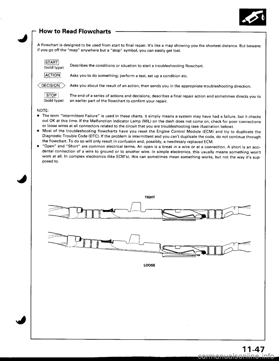
A flowchart is designed to be used from start to final repair. lt's like a map showing you the shone$ distance. But beware:if you go off the "map" anywhere but a "stop" symbol, you can easily get lost.
FTARN(bold type)
FcroNl
@>
sroFl
(bold type)
NOTE:
. The term "lntermittent Failure" is used in these chans. lt simply means a system may have had a failure, but it checksout OK at this time. lf the Malfunction lndicator Lamp (MlL) on the dash does not come on, check for poor connectionsor loose wires at all connectors related to the circuit that you are troubleshooting (see illustration below).. Most of the troubleshooting flowcharts have you reset the Engine Control Module (ECM) and try to duplicate theDiagnostic Trouble Code (DTC). lf the problem is intermittent and you can't duplicate the code, do not continue throughthe flowchart. To do so will only result in confusion and, possibly, a needlessly replaced ECM.. "Open" and "Short" are common electrical terms. An open is a break in a wire or at a connection. A short is an acci-dental connection of a wire to ground or to another wire. In simple electronics, this usually means something won,twork at all. In complex electronics (like ECM's), this can sometimes mean something works, but not the way rr s sup-posed 10.
Describes the conditions or situation to start a troubleshootinq flowchart
Asks you to do something; perform a test, set up a condition etc.
Asks you about the result of an action, then sends you in the appropriate troubleshooting direction.
The end of a series of actions and decisions, describes a final repair action and sometimes direcls you toan earlier part of the flowchart to confirm your repair.
11-47
Page 254 of 1681
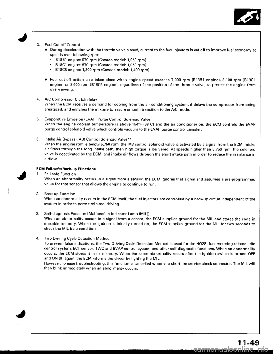
3.Fuel Cut-off Control
. Du ring dece leration with the th rottle va lve closed, cu rrent to the fuel injectors is cutoffto improvefuel economyat
speeds over following rpm:. B'1881 engine: 970 rpm {Canada model: 1.050 rpm). B18C1 engine:970 rpm {Canada model: 1.050 rpm). 818C5 engine: 1,300 rpm (Canada model: 1,400 rpm)
. Fuel cut-off action also takes place when engine speed exceeds 7,000 rpm (B'1881 engine), 8.100 rpm (818C1
engine) or 8,600 rpm (818C5 engine), regardless ol the position of the thronle valve, to protect the engine from
over-revving.
A,,/C ComDressor Clutch Relav
When the ECM receives a demand for cooling from the air conditioning system, it delays the compressor from being
energized, and enriches the mixture to assure smooth transition to the A,/C mode.
Evaporative Emission (EVAP) Purge Control Solenoid Valve
When the engine coolanl temperature is above '154'F (68'C) and the air conditioner on. the ECM controls the EVAPpurge control solenoid valve which controls vacuum to the EVAP purge control canister.
Intake Air Eypass (lAB) Control Solenoid Valve*a
When the engine rpm is below 5,750 rpm, rhe IAB control solenoid valve is activated by a signal from the ECM, intake
air flows through the long intake path, then high torque is delivered. At speeds higher than 5,750 rpm, the solenoidvalve is deactivated by the ECM, and intake air flows through the short intake path in order to reduce the resistance in
airflow.
Sell-diagnosis Function lMalfunction Indicator Lamp {MlL)lWhen an abnormality occurs in a signal from a sensor, the ECM supplies ground for the MIL and stores the code in
erasable memory. When the ignition is initially turned on, the ECM supplies ground for the N4lL tor two seconds to
check the MIL bulb condition.
Two Driving Cycle Detection Method
To prevent false indications, the Two Driving Cycle Detection Method is used for the HO2S, fuel metering-related, idle
control system, ECT sensor, TWC and EVAP control system and other self-diagnostic functions, When an abnormality
occurs, the ECM stores it in its memory. When the same abnormality recurs after the ignition switch is turned OFFand ON (ll)again, the ECM informs the driver by lighting the MlL.
However, to ease troubleshooting, this function is cancelled when you shon the service check connector. The MIL will
then blink immediately when an abnormality occurs.
4.
5.
6.
3.
4.
ECM Fail-safe/8ack.up F0nctions
1. Fail-sate Function
When an abnormality occurs in a signal from a sensor, the ECM ignores that signal and assumes a pre-programmed
value for that sensor that allows the enqine to continue to run.
2. Back-uo Function
When an abnormality occurs in the ECM itself, the fuel injectors are controlled by a back-up circuit independent of the
system in order to permit minimal driving.
11-49
Page 255 of 1681
I
I
It:
PGM-FI System
Engine Control Module {ECMI
,i
I
{
ili
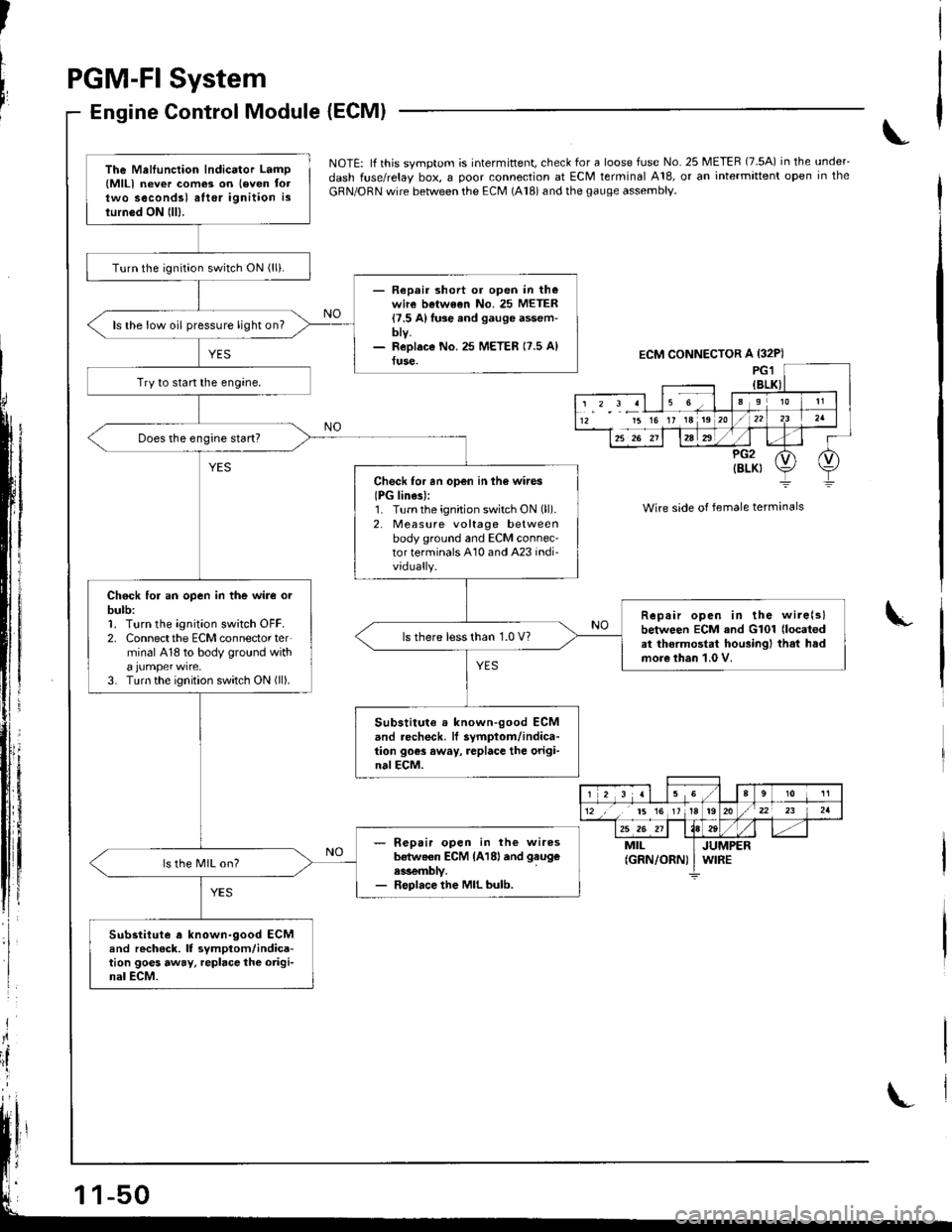
NOTE: lf this svmotom is intermittent, check for a loose fuse No. 25 METER (7.5A) in the under_
dash fuse/relay box, a ooor connection at ECM terminal A18, or an intermittent open in the
GRN/ORN wire between the ECM (A18) and the gauge assembly.
Wire side of female terminals
I
The Mellunction Indicator Lamp(MlLl never com€3 on leven foltwo secondsl alter ignition islurn6d ON lll).
Turn the ignition switch ON (lli.
- Repair short or open in th€wire betwe€n No. 25 METER{7.5 A}fuse and gauge assem-bty.- ReDlaco No.25 METER 17.5 A)fuse.
ls the low oil pressure light on?
Try to start the engine,
Check for an open in ih6 wires
IPG lines):1. Turnthe ignition switch ON (ll).
2. Measure voltage betweenbody ground and ECM connec-tor terminals A10 and A23 indi-vidually.
Chock for an open in the wire orbulb:1. Turn the ignition sw;tch OFF.2. Connectthe ECM connector terminal 418 to body ground with
3. Turn the ignition switch ON (ll).
Repair open in the wire(slbetween ECM and G101 (located
at thermostat housingl that hadmore than 1.0 V.
ls there less than 1.0 V?
Substitute . known-good ECMand .echeck, lf symptom/indica-tion goes away, replace the origi-nalECM.
- R€pair open in the wiresb€tweon ECM {A18land gaug€
ess€mbly.- Replace the MIL bulb.
ls the MIL on?
Substitute a known-9ood ECMand rech6ck. It symptom/indica-tion goes away, repbce the origi-nal ECM.
ECM CONNECTOR A {32P)
15 16 17 18 19
r 2 3 al 15 Ga910 11
12 ,, t5 16 1tt920/22 23 2a
25 26 211184tt-MILJUMPER(GRN/ORN) I WIRE
Page 256 of 1681
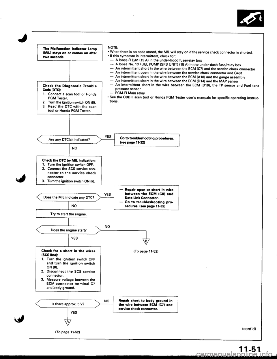
NOTE:. Whon there is no cod6 stored, the MIL willstay on iftho aorvice check conn€ctor is snoned.' lfthis symptom is intermittent. check tor:- A loos6 Fl E/M (15 A) in the undor-hood tuse/relav box- A loose No. 13 FUEL PUMP {SRS UNIT) (15 A) in th6 under-dash fuse/retay box- An intermitt6nt short in the wir€ betwesn the ECM (C7) and th€ sorvice chock conn€qor- An intormittent open in the wire between the sorvice chsck conneclor and G40l- An intermittent short in the wire betwo€n the ECM (A18) and the gaug6 assemDry- An intermittent shon in the wir6 between the ECM (D14) and the MAP sonsor- An intermittent shon in the wire bstween the ECM (Dto), th6 Tp sensor and Fu6l tankpI6SSU16 SOnSOT- PGM-FI Main relay. See th6 OBD ll scan tool or Honda PGM Tester user's manuals for sp6cific operating instruc-!ons.
(To page 11-52)
(cont'd)
Th. M.lfunction Indic.tor LlmplMlll .t!yr on or comlr on ltt .two aaconda.
Ch.ck th! Dirgnoitic tioubl.Cod. IDTC):'1. Connoct a 6can tool or HondaPGM Tester,2. Turn tho ignition switch ON (ll).3. Read tho DTC with the scantool or Honda PGM T6st6r.
Go to trouHorhooting proQduaaa.
koo p.g6 I 1.3:ll
Ch.ct th. DTC by MIL indication:1. Turn th€ ignition switch OFF.2. Connect the SCS seNic€ con-n€ctor to the sorvico checkconnoctor,3. Turn the ignition s1\,itch ON (ll).
Rapair opan or ahort in wirabotw..n thg ECM lCSl .ndData Llnk Conncctor.Go lo troublcrhootlng pro-c.dur.3. {.co pag. 11-32)
Do.s th6 MIL indicate anv DTC?
Try to start tho engine.
Chack lor r 3hort in th. wlr.3lsqg lln.):1. Turn the ignition switch OFFand turn the ignition switchoN { },2. Disconnect th6 SCS serviceconnector,3. M€a6urg voltaOe between theECM connoctor torminal C7and body ground.
Rapah 3hort to body ground inlh. wir. b.lw..n ECM lCTl .ndacwica chack connactor.
ls ther6 approx. 5 V?
\{,
(To page 11-52)
11-51
Page 261 of 1681
PGM-FI System
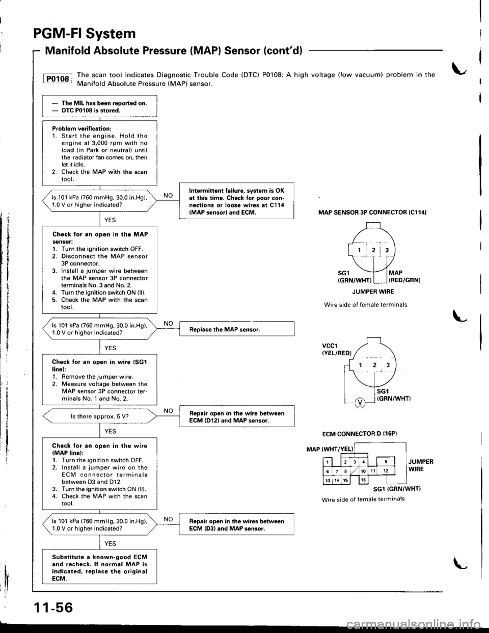
Manifold Absolute Pressure (MAPI Sensor (cont'dl
tF'r'sl li:"J:ilfi::il***:ilHi""k:"
code (Drc) P0108' A hish vo*ase (row vacuum) probrem in the
Thc MIL has b6en reoortod on.OTC P0108 is stored.
Problem veritication:1. Start the engine. Hold theengine at 3,000 rpm with noload (in Park or neutral) untilthe radiator fan comes on, thenlet it idle.2. Check the MAP wlth the scantool,
Intermittent f.ilure, svstem is OKal this time. Check lor Door con-nections or loose wires at C114{MAP sensor} and ECM.
ls 101 kPa (760 mmHg,30.0 in.l-lg),1.0 V or higher indicated?
Chock tor an opcn in th. MAPs€nsoa:1. Turn the ignition switch OFF.2. Disconnect the MAP sensor3P connector.3. Install 6 jumper wire betweenthe MAP sensor 3P connectorterminals No.3 and No.2.4. Turn the ignition switch ON (ll).
5. Ch€ck the MAP with the scantool.
ls 101 kPa (760 mmHg,30.0 in.Hg),1.0 V or higher indicated?
Check tor an open in wire (SG1
linel:1. Remove the jumper wire.2, Measure voltage between theMAP sensor 3P connector teFminals No. I and No.2.
Repair open in the wire betweenECM l012l and MAP s€nsor.ls there approx.5 V?
Check for an open in the wire{MAP line):1. Turn the ignition switch OFF.2. Install a jumper wire on theECM co n nector terminalsbetween D3 and Dl2.3. Turn the ignition switch ON lll).4. Check the MAP with the scantool,
ls 101 kPa (760 mmHg,30.0 in.Hg),1.0 V or higher indicated?Repair open in the wires betweenECM {D3, and MAP s6Gor.
Substitut€ a known-good ECMand recheck. It normal MAP isindicaied, rgplace the originalECM.
MAP SENSOR 3P CONNECTOR {C114}
Wire side of female terminals
L
vccr{YEL/RED)
MAP IWHT
JUMPERWIRE
SG1 (GRN/WHT}
Wire side of female terminals
1 1-56
{GRN/WHT)I ] {RED/GRN)
ECM CONNECTOR D {16P}
L
Page 262 of 1681
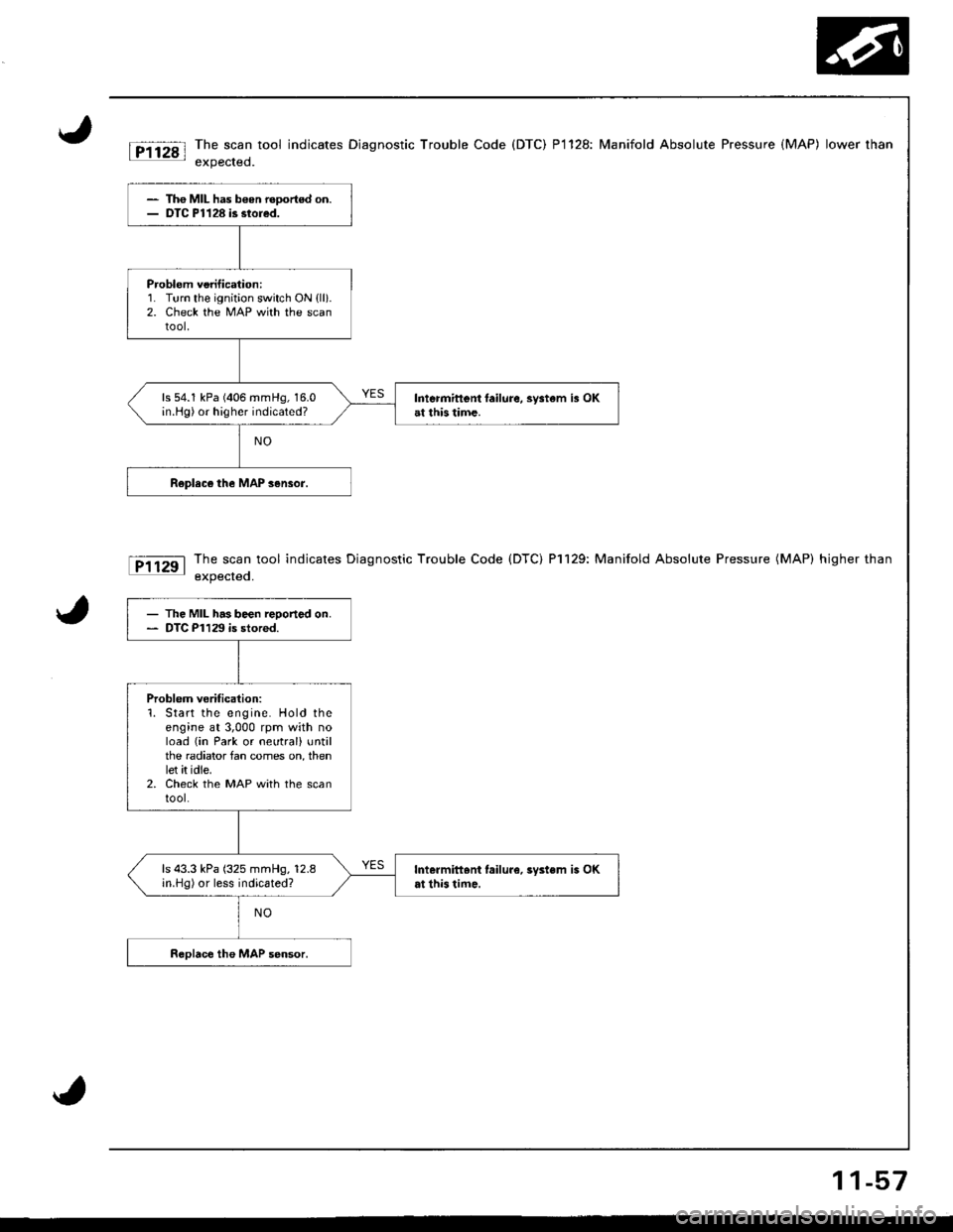
The scan tool indicates Diagnostic Trouble Code (DTC) P1128: Manifold Absolute Pressure (MAP) lower rhan
expected.
The scan tool indicates Diagnostic Trouble Code (DTC) P1129: Manifold Absolute Pressure (MAP) higher than
expected.
- Th€ MIL has b€en reoortod on.- DTC Pl128 is stored.
Problem vorification:1. Turn the ignition switch ON {ll}.2. Check the MAP with the scantool,
ls 54.1 kPa (406 mmHg, 16.0in.Hg) or higher indicated?Intermittent laihre, system i3 OKat this time.
- The MIL has been reooned on.- DTC P1129 is stored.
Problem verification:1. Start the engine. Hold theengine at 3,000 rpm with noload (in Park or neutral) untilthe radiator fan comes on, thenlet it idle.2. Check the MAP with the scantool.
ls 43.3 kPa (325 mmHg, 12.8in.Hg) or less indicated?Intermittoni lailure.3ystem is OKat this time.
11-57