check engine HONDA INTEGRA 1998 4.G Owner's Manual
[x] Cancel search | Manufacturer: HONDA, Model Year: 1998, Model line: INTEGRA, Model: HONDA INTEGRA 1998 4.GPages: 1681, PDF Size: 54.22 MB
Page 185 of 1681
Oil Pump
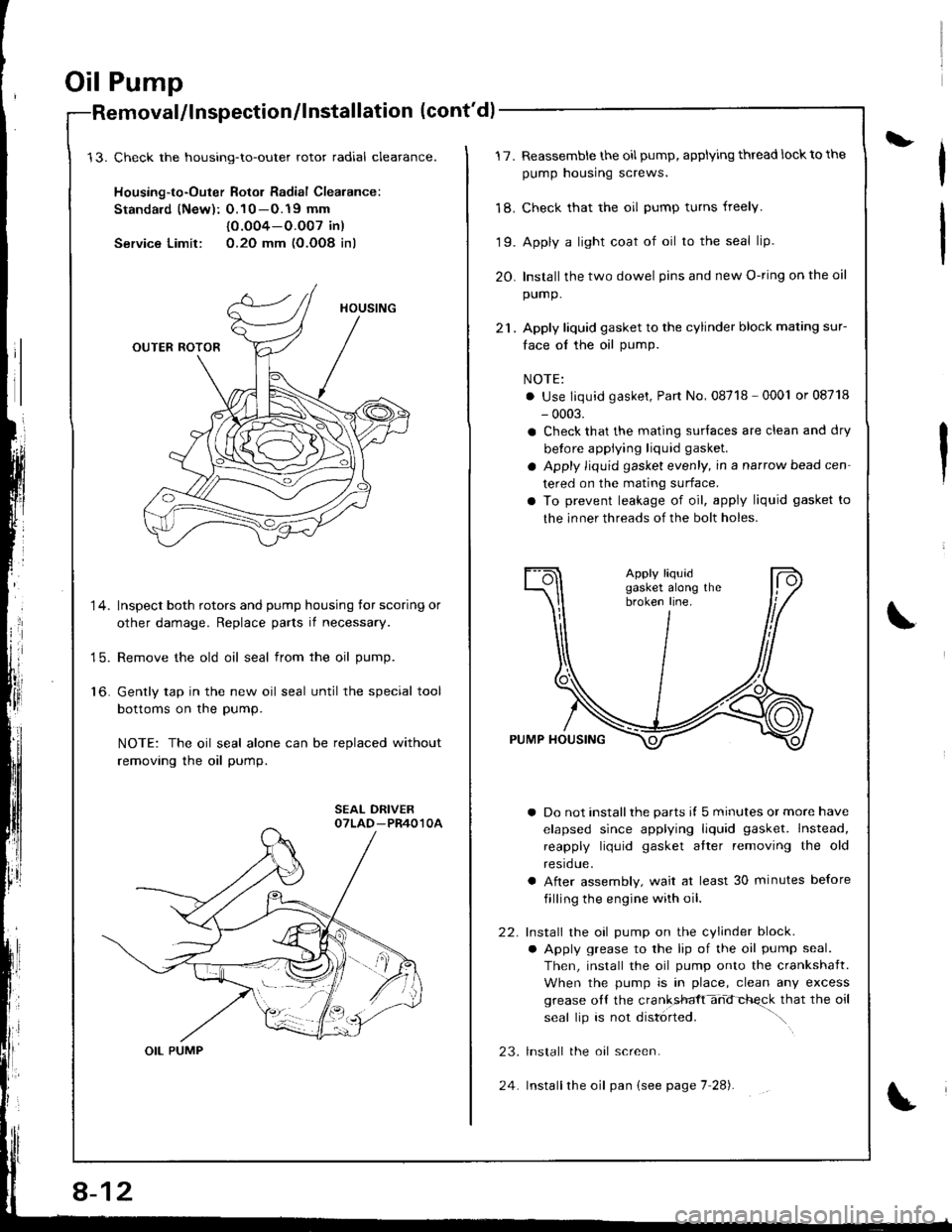
Check the housing-to-outer rotor radial cleatance.
Housing-to-Outer Rotor Radial Clearance:
Standald (New): O.10 -O.19 mm
{0.O04-O.O07 in)
Service Limit: 0.2O mm (O.OO8 inl
Inspect both rotors and pump housing tor scoring or
other damage. Replace parts if necessary.
Remove the old oil seal from the oil pump.
Gently tap in the new oil seal until the special tool
bottoms on the pump.
NOTE: The oil seal alone can be replaced without
removing the oil pump.
alllnspection/lnstallation (cont'd)
14.
15.
to.
OIL PUMP
8-12
24
L17.
'18.
19.
20.
Reassemble the oil pump, applying thread lock to the
pump housing screws.
Check that the oil pump turns freely.
Apply a light coat of oil to the seal lip.
Install the two dowel pins and new O-ring on the oil
pump.
Apply liquid gasket to the cylinder block mating sur-
face ol the oil pump.
NOTE:
. Use liquid gasket, Part No, 08718 - 0001 or 08718
- 0003.
a Check that the mating surlaces are clean and dry
betore applying liquid gasket.
a Apply liquid gasket evenly, in a narrow bead cen
tered on the mating surface.
a To prevent leakage of oil, apply liquid gasket to
the inner threads of the bolt holes.
a Do not installthe parts il 5 minutes or more have
elapsed since applying liquid gasket. Instead,
reapply liquid gasket atter removing the old
resrdue.
a After assembly, wait at least 30 minutes before
filling the engine with oil.
Install the oil pump on the cylinder block.
a Apply grease to the lip of the oil pump seal.
Then, install the oil pump onto the crankshaft.
When the pump is in place, clean any excess
grease oll the cranksfft-hd-chqck that the oil
seal lip is not disl6rted. ".\
lnstall the oal screen.
Installthe oil pan (see page 7 28).
22.
23.
Page 187 of 1681
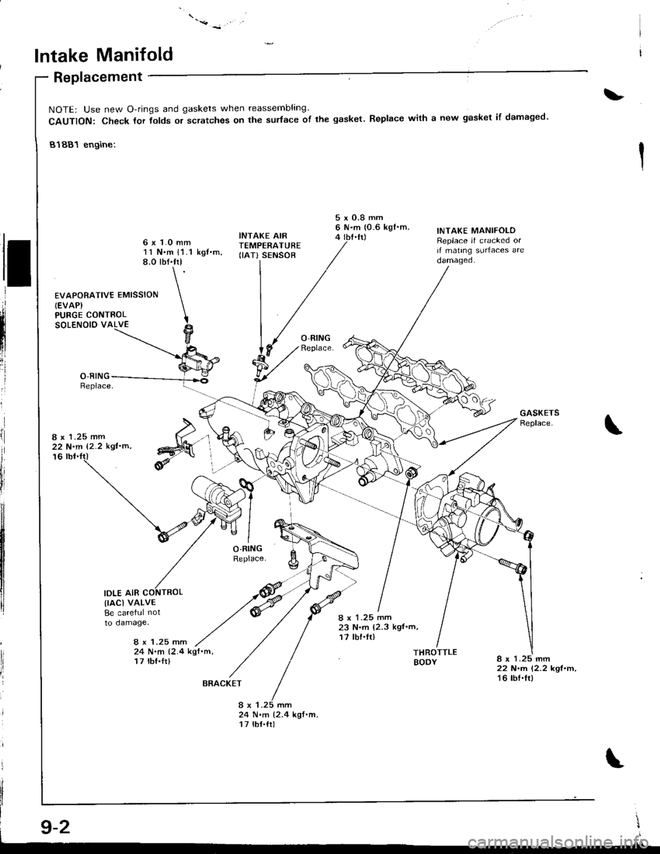
lntake Manifold
Replacement
PURGE CONTROLSOLENOIO VALVE
8 x 1.25 mm22 N.m 12.2 kgl'm'
16
IDLE AIR
\
NOTE: Use new O-rings and gaskets when reassembling
CAUTION: Check tor tolds or scratches on the sudace of the gasket.
81881 engine:
Replace with a new gasket if damaged.
&
d
ll
,ii
ilnl
iii
I
I
ii
il
lli
fr
EVAPORATIVE EMISSION(EVAP}
11 N.m l'1.1 kg{.m,8.0 rbf.fr)
INTAKE AIRTEMPERATURE(IAT} SENSOB
5xO.8mm6 N.m 10.6 kgf'm,4 tbI.tt)
8 x 1.25 mm23 N.m (2.3 kgt'm,17 tbf.fl)
INTAKE MANIFOLOReplace if cracked orif mating surfaces areoamageo.
lrAcl vALvEBe careful not
to damage,
8 x 1.25 mm24 N.m 12.4 kqf .m,
17 lbI.Ir)THROTTLEBODY8 x 1.25 mm22 N.rn 12.2 kgl.m,16 tbf.frl
24 N.m {2.4 kgt.m,17 tbf.{r)
\I
.lll
BRACKET
Page 188 of 1681
.'.,.'.attj
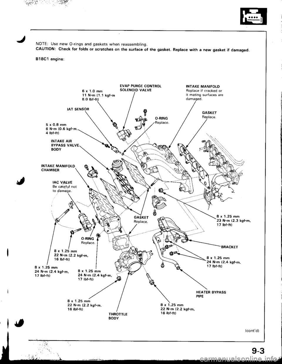
NOTEr Use new O-rings and gaskets when reassembling.CAUTION: Check for folds or scratches on the surlace ot the gasket. Replace with a new gasket if damaged.
818C1 engine:
6 x 1.0 mm11 N.m {1.1 kgt.m8.O tbt.trl
EVAP PURGE CONTROLSOLENOID VALVEINTAKE MANIFOLDReplace if cracked orit mating surfaces are
rAc v4f,vE8e caie{ul notto
IAT SENSOR
8 x 1.25 mm24 N.m 12.4 kgt.m,17 tbf'fr)
22 N.m 12.2 k'l.m,16 lbf.ftl
O-BINGReplace.5x0.8mm6 N.m (0.6 kgI'm,4 tbf.trl
INTAKE AIRBYPASS VALBODY
INTAKE MANIFOLOCHAMBER
8 x 1.25 mm23 N.m 12.3 kgt.m,17 tbf.ft)
8 x 1.25 mm22 N.m 12.2 kgt.m,16 tbt'tr)I x 1.25 mm24 N.m (2.4 kgl.m,17 tbf.ft)8 x 1.25 mm24 N.m (2.4 kgt.m,17 tbf.frl
HEATER BYPASSPIPE
8 x 1.25 mm22 N.m 12.2 kgt.m,16 lbt.fr)THROTTLEEODY
(cont'd)
9-3
Page 189 of 1681
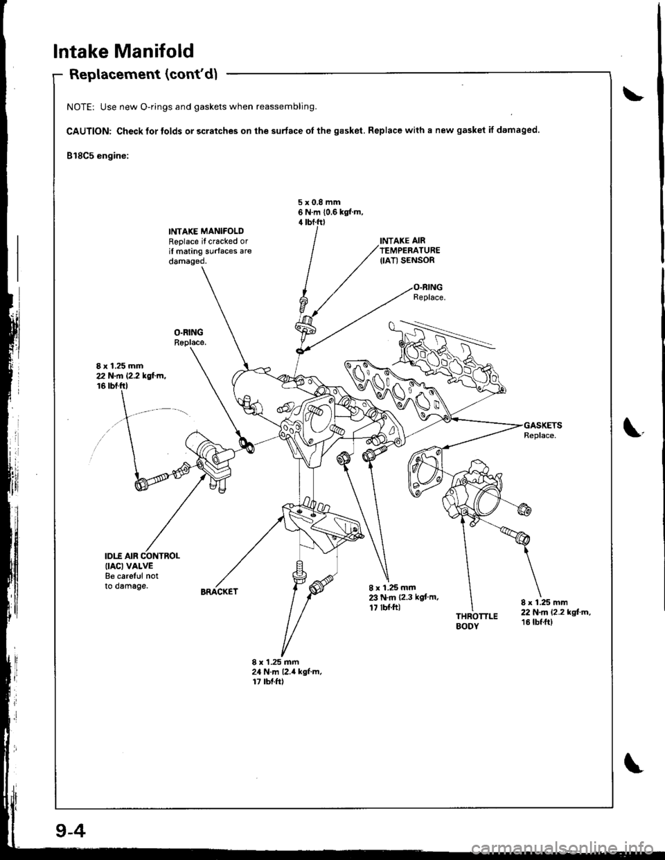
Intake Manifold
Replacement (con(d)
NOTE: Use new O-rings and gaskets when reassembling.
CAUTION: Check for tolds or scratches on the surface oI the gasket. Replace with a new gasket if damaged
818C5 engine:
5x0,8mm6 N.m 10.6 kgl m,
INTAKE MANIFOLDRoplace il cracked oril mating surfaces aredamaged.
I x 1.25 mm212 N.n 12.2 tsl'm,16 tbf.ftl
\.
IDI.f AIR CONTROL(IACI VALVEBe careful notto dsmage.8 x 1.25 mmZ' N.m 12.3 kgt'm,17 tbl.ft)THROTTLEBODY
8 x 1.25 mm22 N.m 12.2 kgtm,16 tbf ft)
8 x'1.25 mm24 N.m l2.il kgf.m,17 rbt.ft)
9-4
Page 192 of 1681
J
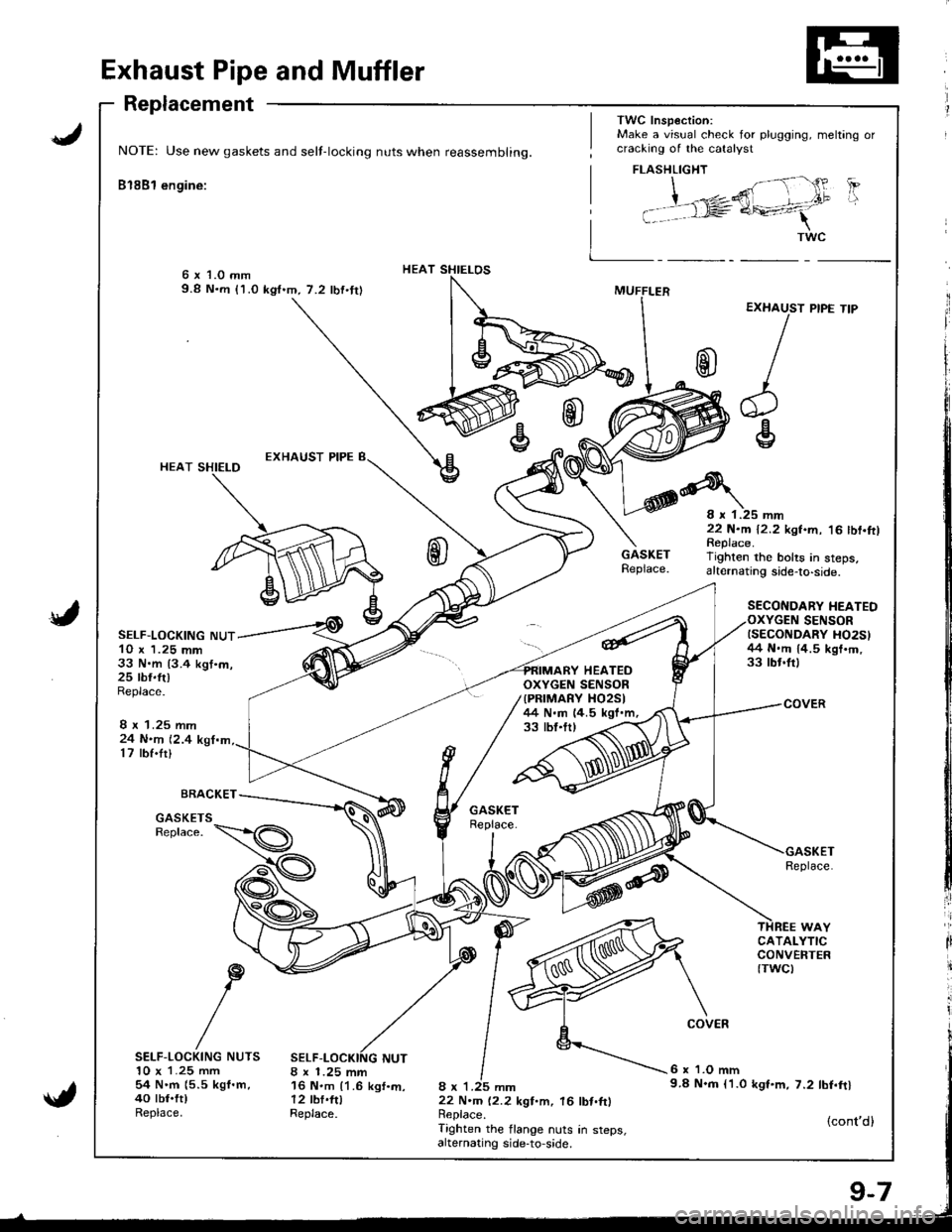
Exhaust Pipe and Muffler
Replacement
NOTE: Use new gaskets and self-locking nuts when reassembling.
Bl8Bl engine:
HEAT SHIELOS6 x 1.0 mm9.8 N.m (1.0 kgf.m,7.2 lbf.tr)
{
HEAT SHIELD
SELF-LOCKING NUT10 x 1.25 mm33 N.m {3.4 kgt.m,25 rbr.ft)Replace.
24 N.n 12.417 rbf.tr)
BRACKET
8 x 1.25 mm16 N.m {1.6 kgf.m,12 tbf.fttReplace.
33 tbt.tr,
8 x 1.25 mm22 N.m 12.2 kgf.m. 16 lbt.ftlReplace.Tighten the flange nuts in steps,alternating side-to,side.
Replace.
6 x 'l.O mm9.8 N.m l'1.0 kgt.m, 7.2 tbf.ftl
{cont'd}
GASKETSReplace.
ir
li
it
SELF-LOCKING NUTS10 x 1.25 mm54 N.m {5.5 kgf.m,40 tbt.ft)Replace.
TWC Insp€ction:Make a visual check for plugging, meltang orcracking of the catalyst
EXHAUST
/
r
HEATEDOXYGEN SENSOR{PRIMARY XO25I/+4 N.m 14.5 kgf.m,
FLASHLIGHT
| ;"1- {' 'PI i ,"*,2ffi - .t"
i t rl= a+-41
I _ _*"
PIPE TIP
8 r 1.25 mm22 N.m 12.2 kgf.m, '16 tbf.ftlReplace.Tighten rhe bolts in steps,altelnating side-to-side.
SECONDARY HEATEDSENSORISECONDARY HO2S}/+4 N.rn 14.5 kgt'm,33 tbr.frl
9-7
Page 196 of 1681
lllustrated Index
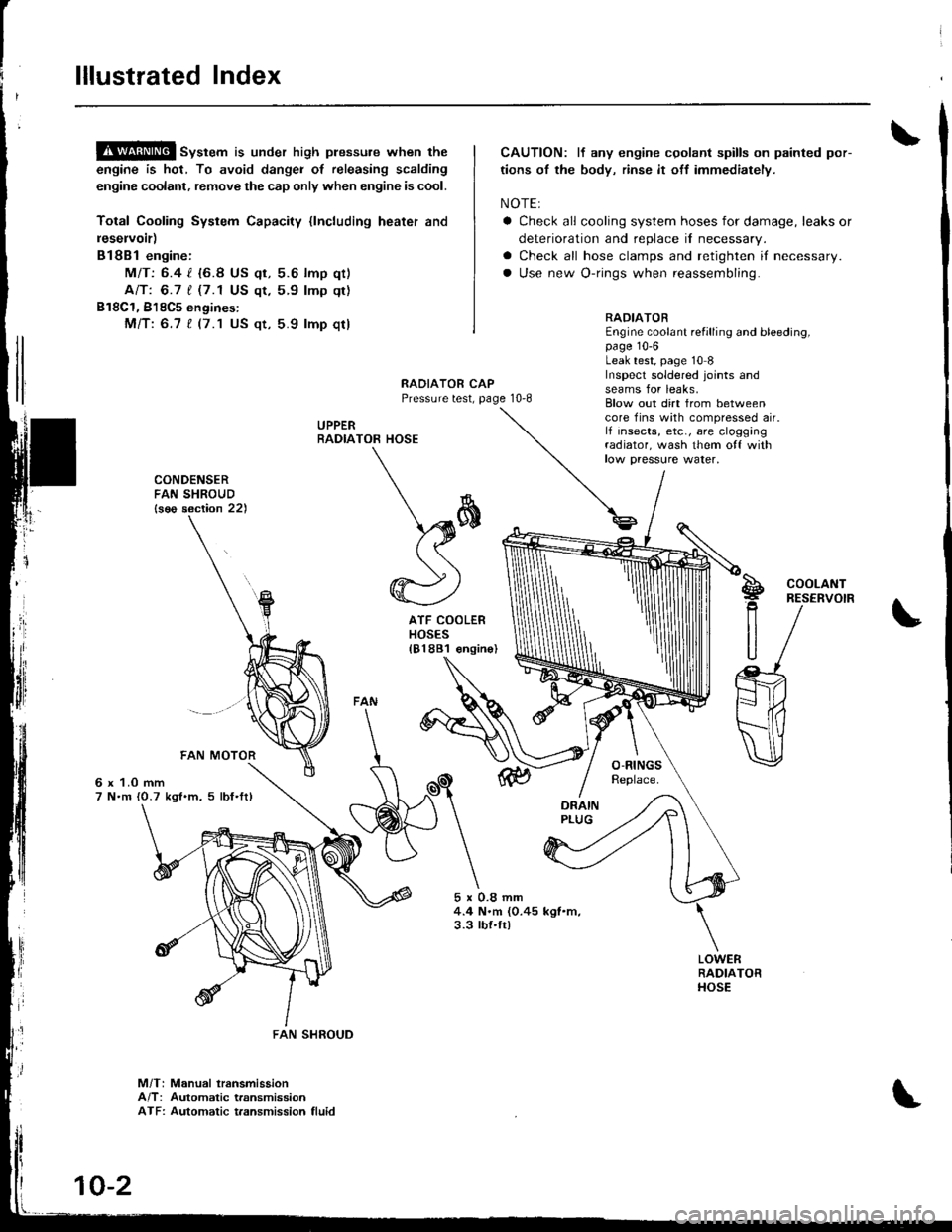
!$!!@ sv"t"m is under high plessure when the
engine is hot, To avoid dangei of releasing scalding
engine coolant, remove the cap only when engine is cool.
Total Cooling System Capacity {lncluding heater and
leservoir)
Bl8Bl engine:
MIT: 6.4 l. {6.8 US qt, 5.6 lmp qt)
Ant 6.7 t (7.1 US qt,5.9 lmp qt)
B18C1, 818C5 engines:
Mfi:6.7 t (7.1 US qt, 5.9 lmp qt)
CAUTION: lf any engine cgolant spills on painted por-
tions of the body, rinse it off immediately.
NOTE:
a Check all cooling system hoses for damage, leaks or
deterioration and replace il necessary.
a Check all hose clamps and retighten if necessary.
a Use new O-rings when reassembling.
RADIATOREngine coolant refilling and bleeding,page 10-6Leak test, page 10 8Inspecl soldered joints andseams for leaks,RAOIATOR CAPPressure test, page 10-8
UPPERRADIA
rl
]
CONDENSERFAN SHROUD{s€o section 22)
6 x 1.0 mm7 N.m {0.7 kgl.m, 5 lbf'ftl
5x0.8mm4.4 N.m (0.45 kgl.m,3.3 tbt.ft)
Blow out dirt from betweencore fins with compressed air.lf insects, etc., are cloggingradiator, wash them o{f withlow paessure water,
TOR HOSE
\*
\sffi((
@)
ATF COOLERHOSES181881 €ngin
S!g
R
U
COOLANTRESERVOIR
M/T: Manual lransmissionA/T: Automatic transmissionATF: Automatic t.ansmission fluid
FAN SHROUD
10-2
Page 201 of 1681
8.Mix the recommended antifreeze with an equal
amount of water in a clean container.
NOTE:
a Use only genuine Honda antifreeze/coolant.
a For best corrosion protection, the coolant concen-
tration must be maintained year-round at 500,6
minimum. Coolant concentrations less than 507o
may not provide sufficient protection against cor,
rosion or freezing.
a Coolant concentrations greater than 60% will im-
pair cooling efliciency and are not recommended.
CAUTION:
a Do not mix different brands of anti-lrcezel
coolants.
a Do not use additional rust inhibitots or anti-tustproducts; they may not be compatible with the
coolant.
Engine Coolant Refill Capacity [including reservoir
{0.6 { (0.6 US qt, 0.5 lmp qr)ll:
81881 engine:
Ml7:1-1t {/t.6 US qt. 3.9 lmp qtl
818B1, 818C1 engin€s:
AlTt 1.7 | 15.0 US qt, 4.1 lmp qt)
818C1, B18C5 engines:
MlTt 1.7 t 15.0 US $, 4.1 lmp qtl
FILLER NECK
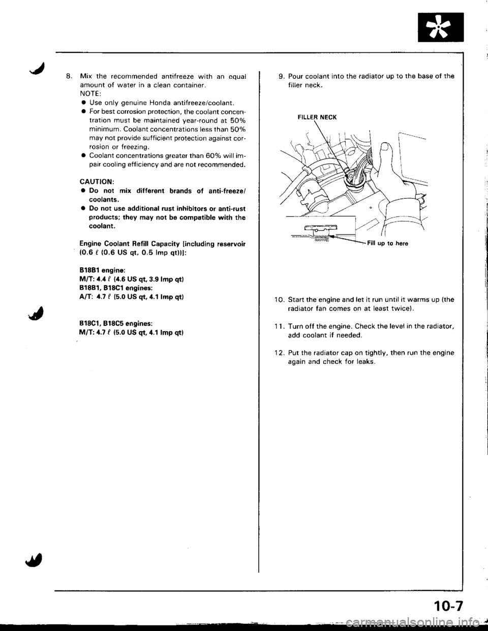
9.Pour coolant into the radiator up to the base of the
tiller neck.
10. Startthe engine and let jt run until itwarmsup(the
radiator fan comes on at least twice).
1 1 . Turn olf the engine. Check the level in the radiator,
add coolant if needed.
'12. Put the radiator cap on tightly, then run the engine
again and check for leaks.
10-7
Page 202 of 1681
Cap Testing
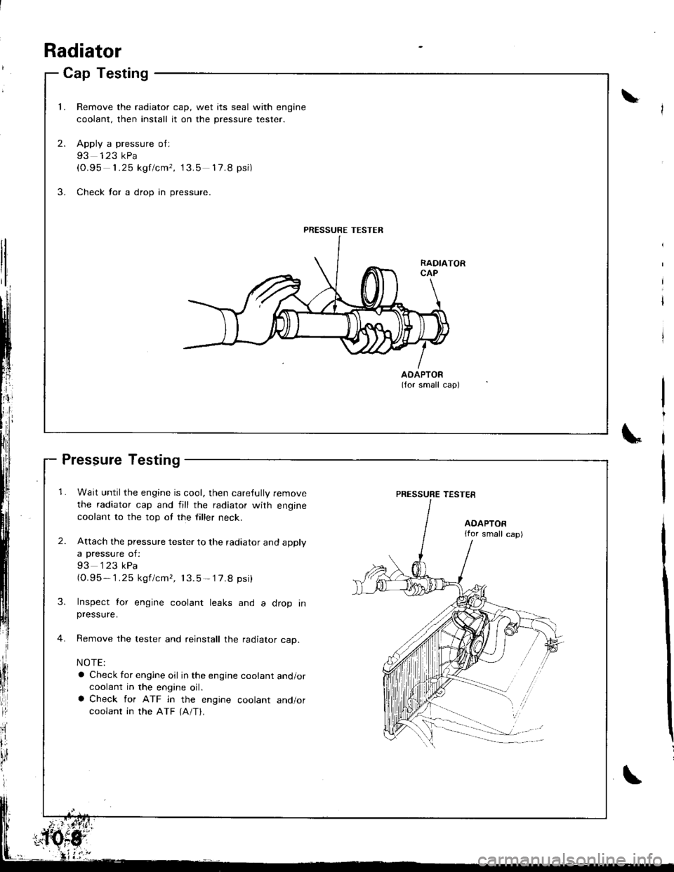
1.Remove the radiator cap, wet its seal with engine
coolant, then install it on the pressure tester.
Apply a pressure of:
93 123 kPa(0.95 1.25 kgf/cm', 13.5 17.8 psi)
Check for a drop in pressure.
2.
3.
AOAPTOR(for small cap)
PRESSURE TESTER
Radiator
Pressure Testing
1. Wait until the engine is cool, then carefully remove
the radiator cap and fill the radiator with engine
coolant to the top ot the filler neck.
2. Attach the pressure tester to the radiator and apply
a pressure of:
93 123 kPa(O.95- 1.25 kgf/cmr, 13.5-'17.8 psi)
3. Inspect lor engine coolant leaks and a drop inpressure.
4. Remove the tester and reinstall the radiator cap.
NOTE:
a Check for engine oil in the engine coolant and/orcoolant in the engine oil.a Check for ATF in the engine coolant and/orcoolant in the ATF {A/T}.
\
PRESSURE TESTES
AOAPTOR{for small cap)
Page 205 of 1681
Inspection
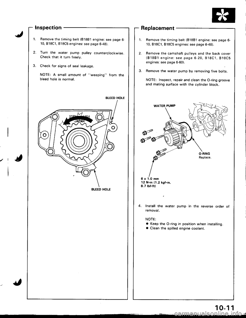
Remove the timing belt (81881 engine: see page 6-10, B'l8Cl,818C5 engines: see page 6-48).
Tu.n the water pump pulley counterclockwise.Check that it turn freely.
Check for sign6 of seal leakage.
NOTE: A small amount of "weeping" trom thebleed hole is normal.
BLEED HOLE
Remove the timing belt (81881 engine: see page 6-
10,818C1, Bl8C5 engines: see page 6-48).
Remove the camshaft pulleys and the back cover(B'1881 engine: see page 6-20, 818C1, 818C5
engines: see page 6-60).
Remove the water pump by removing flve bolts.
NOTE: Inspect, repair and clean the O-ring groove
and mating surface with the cylinder block,
Replacement
6 x 1.0 mm12 N.m 11.2 kgt.m,8.7 tbf.tt)
4. Install the water pump in the reverse order ofremoval.
a Keep the O-ring in position when installing.a Clean the spilled engine coolant.
BLEED HOL€
10-1 1
Page 211 of 1681
Gomponent Locations
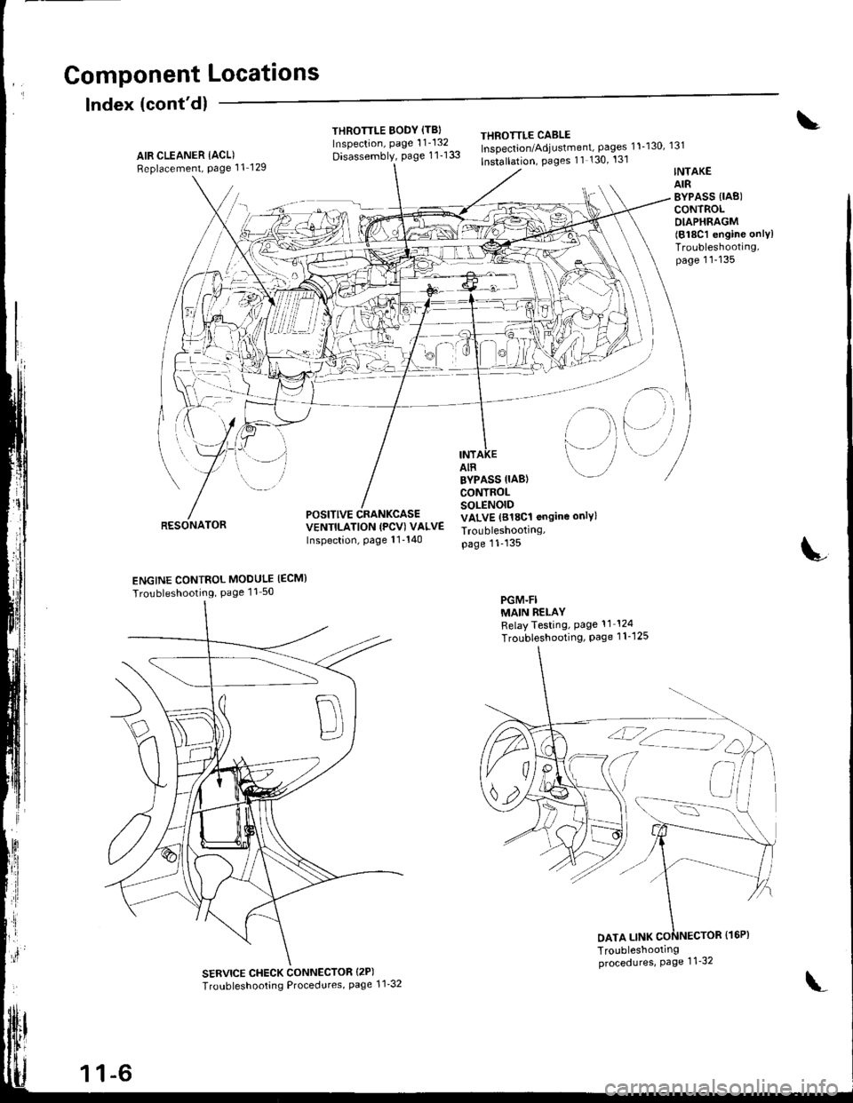
Index (cont'dl
THROTTLE BODY {TBIInspection, page 1 1'132
Disassembly, page 1 1-133
THEOTTLE CABLEInspection/Adjustment, pages 11-130, 131
lnstallation, Pages 11 130' 131AIR CLEANER IACL)Replacement, Page 11 129
RESONATOR
INTAKEAIRBYPASS {IAB)CONTROLDIAPHRAGM(818C1 engine onlylTroubleshooting,page 11-135
i-)
i--- / /
i rl
l'-' i
INTAIR
POSITIVE CRANKCASEVENTILATION (PCV) VALVEInspection, page 11'140
BYPASS IIAB}CONTROLSOLENOIDVALVE (818C1 ongine only)
Troubleshootrng,page 11-135
PGM-FIMAIN RELAYRelayTesting, Page 11 124
Troubleshooting, Page 1 1-1 25
L
ENGINE CONTROL MODULE IECM}
Tro!bleshooting, Page 11 50
SERVICE CHECK CONNECTOR {2P)
Troubleshooting Procedures, page 1 1'32
DATA LINK
1 1-6
\'