fuel pressure HONDA INTEGRA 1998 4.G User Guide
[x] Cancel search | Manufacturer: HONDA, Model Year: 1998, Model line: INTEGRA, Model: HONDA INTEGRA 1998 4.GPages: 1681, PDF Size: 54.22 MB
Page 246 of 1681
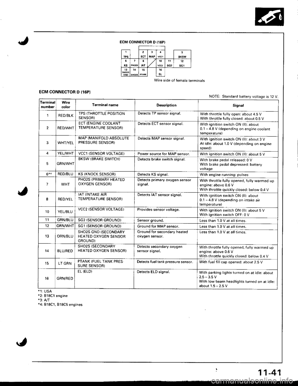
ECM CONNECTOR D (16P}
Wire side of female terminals
ECM CONNECTOR D (16P1NOTE| Standard battery voltage is 12 V.
TerminalnumberWirecolorT6rminal nameDoscriptionSignal
1RED/BLKTPS (THROTTLE POSITIONSENSOR)Detects TP sensor s;gnal.With throttle fully open: about 4.5 VWith throttle fully closed: about 0.5 V
2REDAr'r'HTECT (ENGINE COOLANTTEMPERATUBE SENSOB}Detects ECT sensor signal.With ignition switch ON (ll)r about0.1 - 4.8 V (depending on engine coolanttemperalure)
3WHT//ELMAP {MANIFOLD AESOLUTEPBESSURE SENSOR)Detects MAP sensor signal.With ignition switch ON (ll)iabout 3 VAt idle: about 1.0 V {depending on enginespeeol
4YELA/VHTvccl{SENSOR VOLTAGE)Power source for MAP sensor,With ignition switch ON (ll): about 5 V
5GRNAVHTBKSW (BRAKE SWITCH)Detects brake switch signal.With brake pedal released: 0 VWith brake pedal depressed: batteryvoltage
6*!RED/BLUKS (KNOCK SENSOR}Detects KS signal.With engine running: pulses
lPHO2S (PRIMARY HEATEDOXYGEN GENSOR)Detects primary oxygen sensorsignal.With throttle fully opened, fully warmed upengine: above 0.6 VWith throttle quickly closed: below 0.4 V
8RED/VEL
IAT (INTAKE AIRTEMPERATURE SENSOR)Detects IAT sensor signal.With ignition switch ON {ll): about0.1 - 4.8 V (depending on intake airtemperature)
10YEL/BLUvcc2(SENSOB VOLTAGE)Provides sensor voltage,With ignition switch ON (ll): about 5 VWith ignition switch OFF: 0 V
1lGRN/8LUSG2 (SENSOR GROUND}Sensor ground.Less than 1.0 V at all times.
GFNA/VHT(SENSOR GROUND}Ground tor MAP sensor.Less than 1.0 V at all times.
OBN/BLUSHO2S GND (SECONDARY
HEATED OXYGEN SENSORGROUND)
Ground for secondary heatedoxygen sensor,Less than 1.0 V at alltimes.
148LU/REDSH02S (SECONDARY
HEATED OXYGEN SENSOR}Detects secondary oxygensensor srgnal.With throttle fully opened. fully warmed upengine: above 0,6 VWith throttle quickly closed: below 0.4 V
LT GRNPTANK (FUEL TANK PRESSURE SENSOR)Detects fueltank pressure sensor.With luel fill cap opened: about 2-5 V
GRN/RED
EL (ELOiDetects ELD signal.With parking lights turned on at idle: about2.5 -3.5 VWith low beam headlights turned on at idle:about 1.5 - 2.5 V*1:USA*2: 818C1 engine"3:A"/T*4: B18C'1, 818C5 engines
11-41
Page 247 of 1681
1l
Troubleshooting
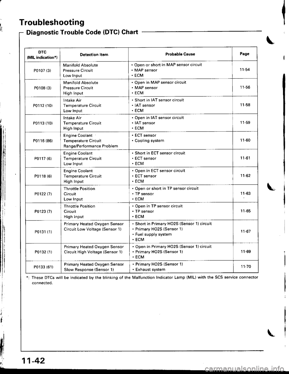
Diagnostic Trouble Gode (DTCI Chart
*: These DTCS will be indicated by the blinking ot the lvalfunction Indicator Lamp (MlL) with the SCS service connector
connected.
Ia
\
\
il
\
DTC
lMlL indication*lDetection ltemProbabls CausePage
P0107 (3)
Manifold Absolute
Pressure Circuit
Low Input
Open or short in MAP sensor circuit
MAP sensor
ECM
'11-54
P0108 (31
Manifold Absolute
Pressure Circuit
High Input
Open in MAP sensor circuit
MAP sensor
ECM
tt-5t,
P0112 (10)
Intake Air
Temperature Circuit
Low Input
Short in IAT sensor circuit
IAT sensor
ECM
11.58
P0113 {10)
lntake Air
Temperature Circuit
High Input
Open in IAT sensor circuit
IAT sensor
ECM
1'�1-59
P0116 (86)
Engine Coolant
Temperature Circuit
Range/Performance Problem
. ECT sensor' Cooling system11-60
P0117 (6)
Engine Coolant
Temperature Circuit
Low Input
Short in ECT sensor circuit
ECT sensor
ECM
1 '�t-61
P0118 {6)
Engine Coolant
Temperature Circuit
High Input
Open in ECT sensor circuit
ECT sensor
ECt\,4
1't -62
P0122l7l
Throttle Position
Circuit
Low Input
Open or shon in TP sensor circuit
TP sensor
ECM
11,63
P0123 (7)
Throttle Position
Circuit
High Input
Open in TP sensor circuit
TP sensor
ECM
I t-oc
P0131 (1 )
Primary Heated Oxygen Sensor
Circuit Low Voltage (Sensor 1)
Shon in Primary HO2S (Sensor'l) circuit
Primary H02S {Sensor 1)
Fuel supply system
ECM
11-67
P0132 (1)Primary Heated Oxygen Sensor
Circuit High Voitage (Sensor 1)
Open in Primary HO2S (Sensor 1) circuit
Primary HO2S (Sensor 1)
ECM
11-69
P0133 (61)Primary Heated Oxygen Sensor
Slow Response (Sensor 1)
. Primary HO2S (Sensor 1). Exhaust system1 1-70
,r:' 11-42
L
Page 249 of 1681
Troubleshooting
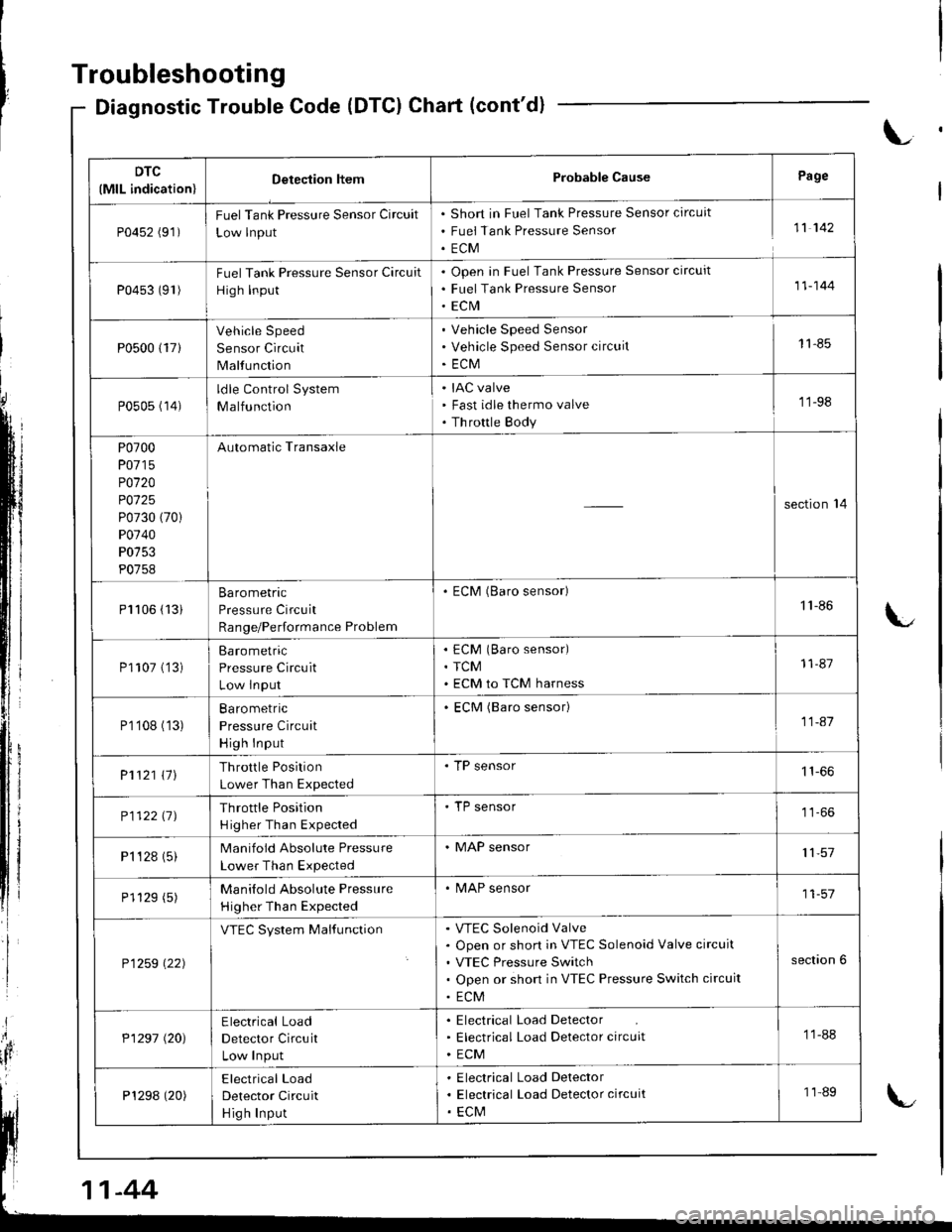
Diagnostic Trouble Code (DTCI Chart (cont'd)
L
DTC
(MlL indication)Detection ltemProbable CausePage
P0452 (91)FuelTank Pressure Sensor Circuit
Low lnput
Short in Fuel Tank Pressure Sensor circuit
Fuei Tank Pressure Sensor
ECM
11 142
P0453 (91)Fuel Tank Pressure Sensor Circuit
High Input
Open in Fuel Tank Pressure Sensor circuit
Fuel Tank Pressure Sensor
ECrVI
11-144
P0500 {17}
Vehicle Speed
Sensor Circuit
Malfunction
Vehicle Speed Sensor
Vehicle Speed Sensor circuit
ECM
11-85
P0505 (14)ldle Control System
Malfunction
IAC valve
Fast idle thermo valve
Th rottle Body
'11-98
P0700
P0715
P0120
P0125
P0730 (70)
P0740
P0753
P0758
Automatic Transaxle
section'14
Pl106 (13iBarometric
Pressure Circuit
Range/Performance Problem
. ECM (Baro sensor)1'l -86
P1107 ('�]3)Barometric
Pressure Circuit
Low lnput
ECM (Baro sensor)
TCM
ECM to TCM harness
11-87
P1'108 (13)Ba ro metric
Pressure Circuit
High Input
ECM (Baro sensor)11-41
P1121 \11Throttle Position
Lower Than Expected
. TP sensor
P112211JThrottle Position
H igher Than Expected
'TP sensor
P1 '�t 28 (5)Manifold Absolute Pressure
Lower Than Expected
. MAP sensor11,57
P1129 (5)Manilold Absolute Pressure
Higher Than Expected
. MAP sensor11-57
P1259 \22)
VTEC System MalfunctionVTEC Solenoid Valve
Open or short in VTEC Solenoid Valve circuit
VTEC Pressure Switch
Open or short in VTEC Pressure Switch circuit
ECM
section 6
P1297 (20)Electrical Load
Detector Circuit
Low Input
Electrical Load Detector
Electrical Load Detector circuit
ECM
11-88
P1298 (20)Electrical Load
Detector Circuit
Hig h Input
Electrical Load Delector
Electrical Load Detector circuit
ECM
11-89
-44
Page 250 of 1681
DTC(MlL indication)Dstection ll€mProbable CausePage
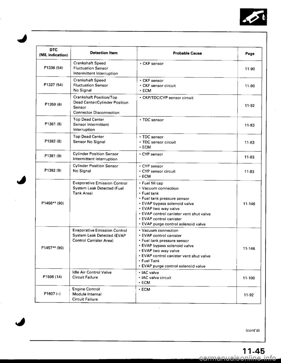
P1336 (54)Crankshaft Speed
Fluctuation Sensor
Intermittent lnterruption
. CKF sensor
1190
Pl337 (54)Crankshaft Speed
Fluctualion Sensor
No Signal
CKF sensor
CKF sensor circuit
ECM
'11-90
P't359 (8)
Crankshaft Position/Top
Dead Center/Cylinder Position
Sensor
Connector Disconnection
CKP/TDC/CYP sensor circuit
1't -92
P1361 (8)Top Dead Center
Sensor Intermittent
Interruptaon
. TDC sensor't1-83
P1352 (8)Top Dead Center
Sensor No Signal
TDC sensor
TDC sensor circuit
ECM
1183
P1381 {9}Cylinder Position Sensor
Intermittent Interruption
. CYP sensor11-83
Pl382 (9)Cylinder Position Sensor
No Signal
CYP sensor
CYP sensor circuit
ECM
11-83
P1456*6 (90)
Evaporative Emission Control
System Leak Detected (Fuel
Tank Area)
Fuel fill cap
Vacuum connection
Fueltank
Fuel tank pressure sensor
EVAP bypass solenoid valve
EVAP two way valve
EVAP control canister vent shut valve
EVAP control canister
EVAP purge control solenoid valve
11-146
P14s7*5 {90)
Evaporative Emission Control
System Leak Detected (EVAP
Control Canister Area)
Vacuum connection
EVAP control canister
Fuel tank pressure sensor
EVAP bypass solenoid valve
EVAP two way valve
EVAP control canister vent shut valve
FuelTank
EVAP purge control solenoid valve
'1 'l - 146
P1508 ( 14)
ldle Air Control Valve
Circuit Failure
IAC valve
IAC valve circuit
ECM
1 1-100
P1607 (-)Engine Control
Module Internal
Circuit Failure
. ECM
11-92
(cont'd)
11-45
Page 253 of 1681
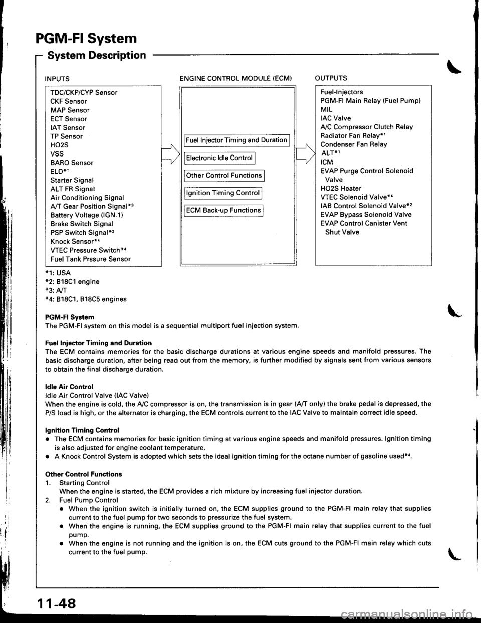
PGM-FI System
System Description
ENGINE CONTROL MODULE (ECM)OUTPUTS
*1: USA*2: 818C1 engine*3: A,/T*4: 818C1, 818C5 engines
PGM-FI Sy3tem
The PGM-Fl system on this model is a sequential multiport fuel injection system.
Fuel lniector Timing and Duration
The ECM contains memories for the basic discharge durations at various engine speeds and manifold pressures. The
basic discharge duration, after being read out from the memory. is further modified by signals sent from various sensors
to obtain the final discharge duration.
ldle Air Control
ldle Ai. Control Valve (lAC Valve)
When the engine is cold, the Ay'C compressor is on. the transmission is in gear (Ay'T only)the brake pedal is depressed, the
P/S load is high, or the alternator is charging, the ECM controls current to the IAC Valve to maintain correct idle speed.
lgnition Timing Control
. The ECM contains memories for basic ignition timing atvarious engine speeds and manifold pressures, lgnitiontiming
is also adjusted for engine coolant temperature.
. AKnockControl System isadoptedwhich sets the ideal ignition timing for the octane n um ber of gasoline used*r,
Other Control Functions
L Starting Control
When the engine is started, the ECM provides a rich mi{ure by increasing fuel injector duration.
2. Fuel PumD Control
. When the ignition switch is initially turned on, the ECM supplies ground to the PGM-FI main relay that supplies
current to the fuel pump for two seconds to pressurize the fuel system.
. When the engine is running, the ECM supplies ground to the PGM-FI main relay that supplies current to the fuel
DUmO.
. When the engine is not running and the ignition is on. the ECM cuts ground to the PGM-FI main relay which cuts
current to the fuel oumo.
INPUTS
TDc/CKP/CYP Sensor
CKF Sensor
MAP Sensor
ECT Sensor
IAT Sensor
TP Sensor
HO2S
VSS
BARO Sensor
ELD*1
Starter Signal
ALT FR Signal
Air Conditioning Signal
A,/T Gear Position Signal*3
Battery Voltage (lGN.1)
Brake Switch Signal
PSP Switch Signal*'�
Knock Sensor*1
VTEC Pressure Switch*4
Fuel Tank Prssure Sensor
Fuel InjectorTiming and Duration
Electronic ldle Control
Other Control Functions
lgnition Timing Control
ECM Back-uD Functions
Fuel-lnjectors
PGM-Fl Main Relay (Fuel Pump)
MIL
IAC Valve
A,/C Compressor Clutch Relay
Radiator Fan Belay*1
Condenser Fan Relay
ALT*1
rcM
EVAP Purge Control Solenoid
Valve
H02S Heater
VTEC Solenoid Valve*'
IAB Control Solenoid Valve*,
EVAP Bypass Solenoid Valve
EVAP Control Canister Vent
Shut Valve
11-48
Page 257 of 1681
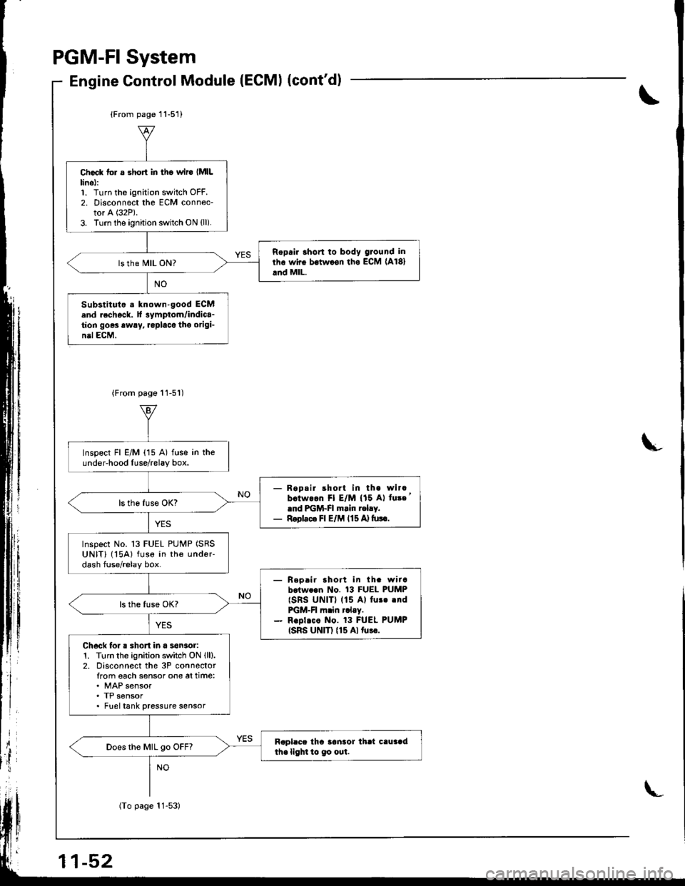
PGM.FISystem
Gontrol Module (ECMI (cont'dlEngine
\
L
(From page 11-51)
Choc* tol s short in tho wir6 lMlLlino):1. Turn the ignition switch OFF.2. Disconn€ct the ECM conn6c-tor A (32P).
3. Turn the ignition switch ON (ll).
Repair 3hon to body ground in
rhe wire bstw.on tho ECM (A181
and MlL.
Substituto s known-good ECMend rechock. H 3ymptom/indica-tion goes awry, replacc tho origi-nelECM,
{From page 11-51)
Inspect Fl E/M (15 A) fuse in theunder-hood Iuse/relay box.
- Ropsir short in tha wircbotw.on Fl E/M {'15 Al tu3c'rnd PGM-FI m.in t.lry.- Rool.c. Fl E/M l15A)tu!€.
Inspect No. 13 FUEL PUMP (SRS
UNIT) ('l5A) fuse in the undeFdash fuse/relay box.
- Reo.ir sholt in th. wirobotw..n No. 13 FUEL PUMP
{SRs UNIT) (15 Al fur..ndFGM-FI m.in rclay.- Repl.co No. 13 FUEL PUMP(SRS UNIT) {15 Alturr.
Ch6ck for . shon in a son3or1. Turn the ignition switch ON (ll).
2. Disconnect the 3P connectorfrom oach sensor one at time:. MAP sensor. TP sensor. Fueltank pressure sensor
Rapl.cc tha 3onaor thrt cauaadihe light to 9o out.Does the MIL go OFF?
1-52
(To page 11-53)
Page 281 of 1681
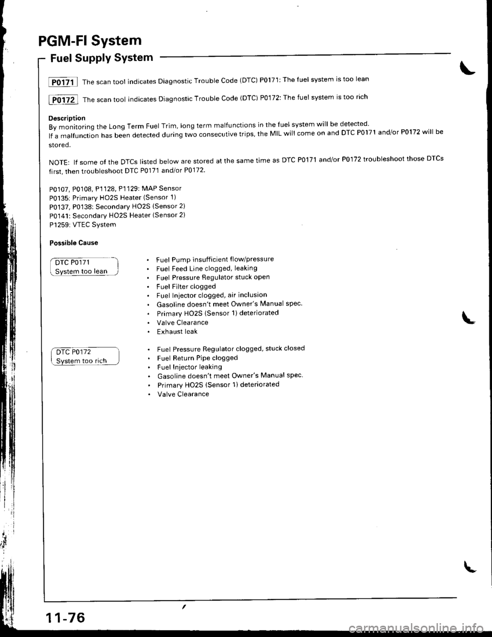
PGM-Fl System
Fuel Supply System
lF0{7il Thescantool indicates Diagnostic Trouble Code (DTC) P0171:Theluel system rstoo lean
[F0i72l Th" ""un tool indicates Diagnosric Trouble code (DTc) p0,172: The fuet system is too rich
Description
By monitoring the Long Term Fuel Trim, long term malfunctions in the luel system will be detected
lf a malfunction has been detected during two consecutive trips, the MIL will come on and DTC P0171 and/or P0172 will be
stored.
NOTE: lf some ol the DTCS lasted below are stored at the same time as DTC PolTl and/or P0172 troubleshoot those DTCS
first, then troubleshoot DTC P0171 andlot P0172
PO107, P0108, P1128. P1129: MAP Sensor
P0135: Primary HO2S Heater (Sensor 1)
P0137, P0138: Secondarv HO2S (Sensor 2)
P0141: Secondary HO2S Heater (Sensor 2)
P1259: VTEC Svstem
Possible Cause
DTC P0171
too lean
Drc P0172
Svstem too rich
. Fuel Pump insufficient flowpressure
. Fuel Feed Line clogged, leaking
. Fuel Pressure Regulator stuck open
. Fuel Filter clogged. Fuel Iniector clogged, air inclusion
. Gasoline doesn't meet Owner's Manual spec.
. Primary HO2S (Sensor 1)deteriorated
. Valve Clearance. Exhaust leak
. Fuel Pressure Regulator clogged, stuck closed
. Fuel Return Pipe clogged
. Fuel Iniector leaking
. Gasoline doesn't meet Owner's Manual spec
' Primary Ho2s (Sensor 1) deteriorated
. Valve Clearance
Page 282 of 1681
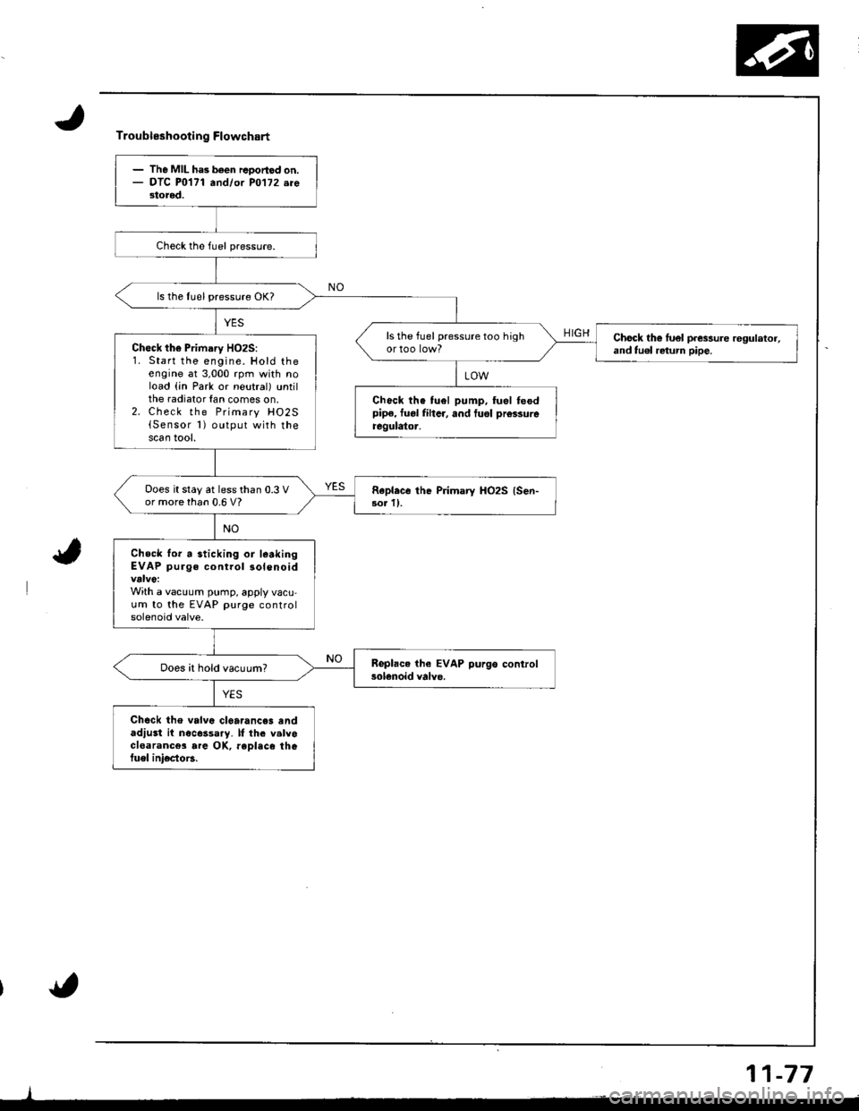
Troubleshooting Flowchart
HIGH
- The MIL ha3 been rcoortod on.- OTC P0171 andlor PO'l72.re3tored.
ls the Iuel pressure OK?
ls the fuel pressure too highChock th€ luel p.essure regulator,and tu€l return pipe.Ch€ck the Primary HO2S:1. Start the engine. Hold theengine at 3,000 rpm with noload (in Park or neutral) untilthe radiator lan comes on.2. Check the Primary HO2S{Sensor 1) output with thescan tool.
Chock the tuel pump, fuel feodpipe, fuol fiher, and tuol prcssureregulator.
Does it stay at less than 0.3 Vor more than 0.6 V?Rapl.ce the Primary HO2S {Sen-3or ll.
Check lor a sticking or l€akingEVAP purge control solenoid
With a vacuum pump, apply vacu,um to the EVAP purge controlsolenoid valve.
Does it hold vacuum?
Chock the valvc cl6a.ance3 andadjust it nocessary. lf th. valvocloarance3 are OK, reDlaco thGtuel ini€cto6.
11-77
Page 283 of 1681
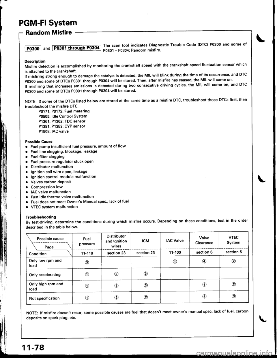
PGM-FI System
Random Misfire
1T0-500 1 a nd Fo-30ittrrousFF0304-lThB scan tool indicates Diagnostic Trouble Code {DTC) P0300 and some of
P0301 - P0304: Random misfire.
Doscription
Misfir; detection is accomplished by monitoring the crankshaft speed with the crankshaft speed fluciuation sensor which
is attached to the crankshsft.
lf misfiring strong enough to damage the catalyst is detected, the MIL will blink during iho time of its occurrence, and DTC
p0300 and some of DTCS p0301 through P0304 will be stor€d. Then, after misfire has ceased, the MIL will come on.
lf misfiring that increases emissions is detected during two consecutive driving cycles, the MIL will come on, and DTC
PO3O0 and some ot DTCS P0301 through P0304 will be stored
NOTE: lJ some of the DTCS listed below are stored at the same time as a misfire DTC, troubleshoot those DTCS first. then
troubleshoot the misfire DTC.
P0171, P0172: Fuel metering
P0505: ldle Control SYstem
P1361, P1362: TDC sensor
P1381. P1382: CYP sensor
P1508: IAC valve
Possible Cause
. Fuel pump insufficient fuel pressure. amount of flow
. Fuel line clogging, blockage, leakage
. Fuel {ilter clogging
a Fuel pressure regulator stuck open
. Distributormallunction
o lgnition coil wire open, leakage
. lgnition control module malfunction
. Valves carbon deposit
a Compression low
. IAC valve malfunction
. Fast idle thermo valve malfunction
o Fuel does not meet Owner's Manual spec., lackotfu€l
. VTEC system malfunction
Troubleshooting
By test-driving, determine the conditions during which misfire occurs. Depending on these conditions, test in the order
described in the table below.
Fuel
pressure
Distributor
and lgnition
wires
tcMIAC ValveValve
Clearance
wEc
System
11118section 23section 231 1- 100section 6section 6
Only low rpm and
loao@o@@
Only acceleratingo@o
Only high rpm and
loado@@@o
Not specificationo@@@@
NOTE: lf misfire doesn't recur, some possible causes arefuel that doesn't meet owner's manual spec, lackoffuel, carbon
deposits on spark plug, etc.
11-78
Page 320 of 1681
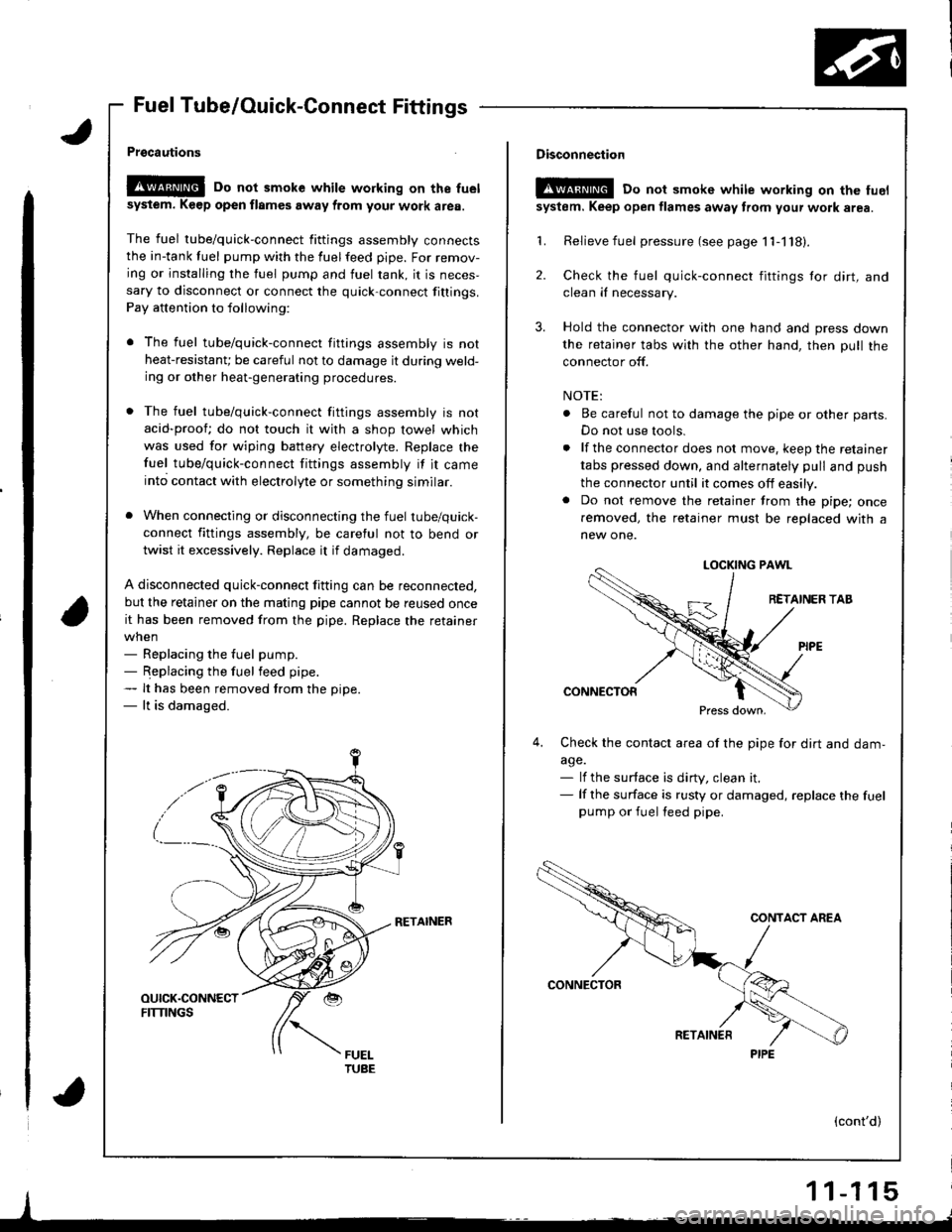
Fuel Tube/Ouick-Connect Fittings
Prgcautions
!@@ Do not smoke while working on the fuel
sysiem. K€ep open flames away from your work area.
The fuel tube/quick-connect fittings assembly connectsthe in-tank tuel pump with the fuelfeed pipe. For remov-
ing or installing the fuel pump and fuel rank, it is neces,sary to disconnect or connect the quick-connect fittings.
Pay attention to following:
r The fuel tube/quick-connect fittings assembly is not
heat-resistanU be careful not to damage it during weld-ing or other heat-generating procedures.
. The fuel tube/quick-connect fittings assembly is not
acid-proof; do not touch it with a shop towel which
was used for wiping battery electrolyte. Replace the
fuel tube/quick-connect fittings assembly if it came
into contact with electrolyte or something similar.
. When connecting or disconnecting the fuel tube/quick-
connect fittings assembly, be careful not to bend or
twist it excessively. Replace it if damaged.
A disconnected quick-connect fitting can be reconnected,
but the retainer on the matlng pipe cannot be reused once
it has been removed from the pipe. Replace the retainer
when- Replacing the fuel pump.- Replacing the fuel feed pipe.- It has been removed trom the oiDe.- lt is damaged.
RETAINER
I
Disconnection
t!!@ Do not smokc white working on the fuel
system. Keep open flames away from your wotk area.
'L Relievefuel pressure (see page 11-118).
2. Check the fuel quick-connect fittings tor dirt, andclean iI necessary.
3. Hold the connector with one hand and press down
the retainer tabs with the other hand, then pull the
connector off.
NOTE:
. Be careful not to damage the pipe or other parts.
Do not use tools.
. lf the connector does not move, keep the retainer
tabs pressed down, and alternately pull and push
the connector until it comes off easily.. Do not remove the retainer from the pipe; once
removed, the retainer must be replaced with a
new one.
LOCKING PAWL
RETAINER TAB
CONNECTOR
Press down,
4,Check the contacl area of the pipe for dirt and dam,
a9e.- lf the surface is dirty, clean it.- lf the surface is rusty or damaged, replace the fuelpump or fuel feed pipe.
(cont'd)
1 1-1 15
PIPE