HONDA INTEGRA 1998 4.G Workshop Manual
Manufacturer: HONDA, Model Year: 1998, Model line: INTEGRA, Model: HONDA INTEGRA 1998 4.GPages: 1681, PDF Size: 54.22 MB
Page 321 of 1681
Fuel Supply System
Fuel Tube/Ouick-Connect Fittings (cont'dl
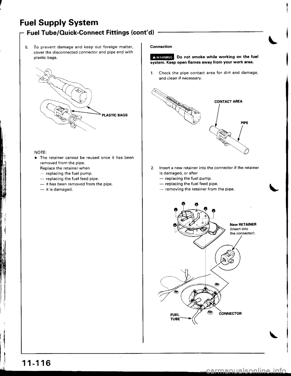
To prevent damage and keep out foreign matter,
cover the disconnected connector and pipe end with
plastic bags.
PLASTIC BAGS
NOTE:
. The retainer cannot be reused once it has been
removed from the pipe.
Replace the retainer when
replacing the fuel pump.
- replacing the fuelfeed pipe.
- it has been removed from the pipe.
- it is damaged.
i
lilf 11-116
IA--- __
\Conneciion
!!@ Do nor smoke wntle workhg on rhe fuel
system. Keep open tlames away trom your work arsa.
L Check the pipe contact area for dirt and damage,
and clean if necessary.
Insert a new retainer into the connector if the retainer
is damaged, or after- replacing the fuel pump.
- replacing the fuelfeed pipe.
- removing the retainer lrom the pipe.
@ dorunecroa
CONTACT AREA
Page 322 of 1681
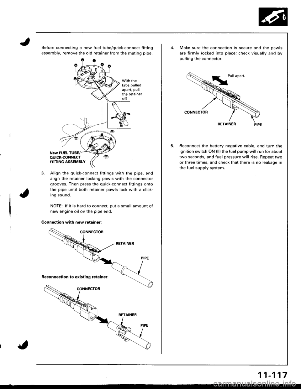
Before connecting a new fuel tube/quick-connect fitting
assembly, remove the old retainer from the mating pipe.
With rhetabs pulled
apart, Pullthe retaineroff
New FUEL TUBE/OUICK.CONNECTFTflNG ASSEMBLY
3. Align the quick-connect fittings with the pipe, and
align the retainer locking pawls with the connector
grooves. Then press the quick connect fittings onto
the pipe until both retainer pawls lock with a click-
Ing souno.
NOTE: lf it is hard to connect, put a small amount of
new engine oil on the pipe end.
Connection with new retainer:
5.
Make sure the connection is secure and the pawls
are lirmly locked into place; check visually and by
pulling the connector.
RETAINER
Reconnect the battery negative cable, and turn the
ignition switch ON (ll) the fuel pump wjll run for about
two seconds, and fuel pressure will rise. Repeat two
or three times, and check that there is no leakage in
the fuel supply system.
11-117
Page 323 of 1681
The fuel supply system co
high pressure fuel pump, t
fuel pressure regulator. f
damper, and fuel delivery i
delivers pressure-regulated
cuts the luel delivery when
Fuel Supply System
System Description
consists of a fuel tank, in-tank
r, PGM-Fl main relay, fueffilter,
. fuel injectors, fuel pulsation
y and return lines. This system
ed fuel to the fuel injectors and
rn thq engine is not running.
Fuel Pressure
Relieving
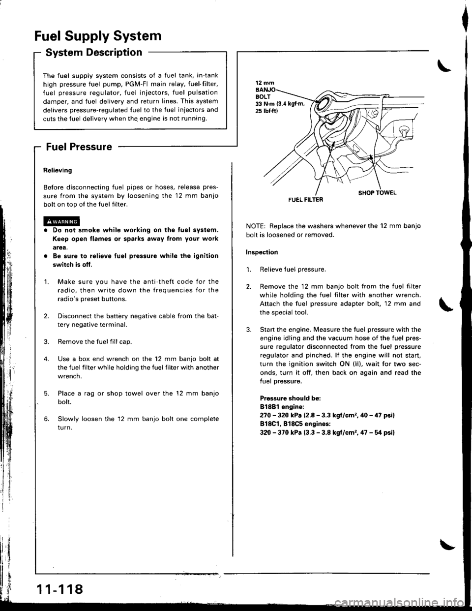
Before disconnecting fuel pipes or hoses, release pres-
sure from the system by loosening the 12 mm banjo
bolt on top ol the fuel filter.
Do not smok€ while working on the tuel system,
Keep open flames or sparks away from you. work
arga.
Be sure to relieve fuel pressure while the ignition
swiich is ofl,
Make sure you have the anti theft code for the
radio, then write down the frequencies for the
radio's preset buttons.
Disconnect the battery negative cable from the bat-
tery negative terminal.
Remove the fuelfill cap.
Use a box end wrench on the 12 mm banjo bolt at
the fuel filter while holding the fuel filter with another
wrench.
Place a rag or shop towel over the '12 mm banjo
bolt.
Slowly loosen the 12 mm banjo bolt one complete
tu rn.
1 1-1 18
I
NOTE| Replace the washers whenever the 12 mm banjo
bolt is loosened or removed.
lnsDection
1. Relieve fuel pressure.
2. Remove the 12 mm banjo bolt from the fuel filter
while holding the fuel tilter with another wrench.
Attach the fuel pressure adapter bolt, 12 mm and
the special tool.
3. Stan the engine. Measure the tuel pressure with the
engine idling and the vacuum hose of the fuel pres-
sure regulator disconnected from the fuel pressure
regulator and pinched. lf the engine will not start,
turn the ignition switch ON (ll), wait for two sec-
onds, turn it off, then back on again and read the
tuel pressure.
Pressuro should be:
Bl8Bl engire:
270 - 320 kP. (2.8 - 3.3 kgl/cm'�.40 - 47 psi)
818C1, 818C5 engines:
320 - 370 kPa (3.3 - 3.8 kgt/cm'�. 47 - g psi)
12 mm
FUEL FILTER
Page 324 of 1681
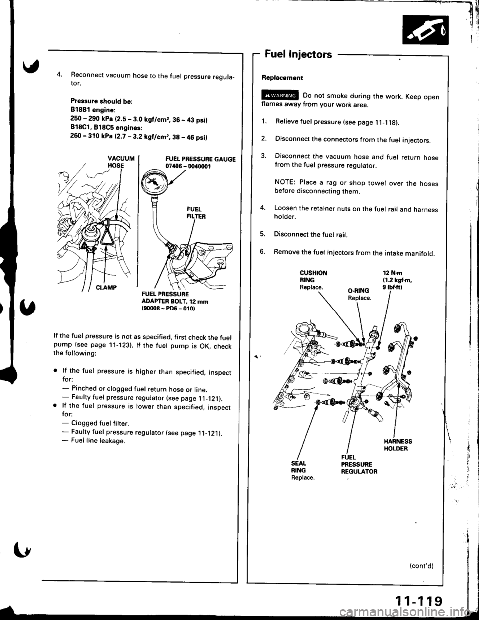
Reconnect vacuum hose to the fuel pressure reguta_ror.
Pressure should be:
818B1 engin€:
250 - 290 kPa (2.5 - 3.0 kgt/cm,, 36 - 4,:t p3i)818C1, B18C5 onginss:
260 - 310 kPa (2.7 - 3.2 kgl/cm,, 38 - 46 psi)
FUEL PRESSURE GAUGE07406 - 004{xr0r
ADAPTER BOIT, i2 mmt90008-PD6_010)
lf the fuel pressure is not as specified, first check the fuelpump (see page 11-123). tf the fuet pump is OK, checkthe following:
. lf the fuel pressure is higher than specified, inspecttor:- Pinched or clogged fuel return hose or line.- Faulty fuel pressure regulator (see page l l _121).. lf the fuel pressure is lower than specified, inspectfor:- Clogged fuel fitter.- Faulty fuel pressure regulator (see page .ll-.121).
- Fuel line leakage.
Fuel Injectors
Rsplac€msnt
!@E oo not smoke during the work. Keep openflames away from your work area.
1. Relieve fuel pressure (see page 1l- g).
2. Disconnect the connectors from the fuel injectors.
3. Disconnect the vacuum hose and fuel return hosetrom the tuel pressure regulatot.
NOTE: Place a rag or shop towel over the hosesbefore disconnecting them.
4. Loosen the retainer nuts on the fuel rail and harnessholder.
Disconnect the fuel rail,
Remove the fuel injectors from the intake manifold.
CUSHIONFINGR.place.
12 N.m11.2 kgt m,I tbfftl
SEALRINGReplace.
VACUUM
FUEL PRESSURE
Page 325 of 1681
I
Fuel Supply System
Fuel Injector (cont'dlFuel Pressure Regulator
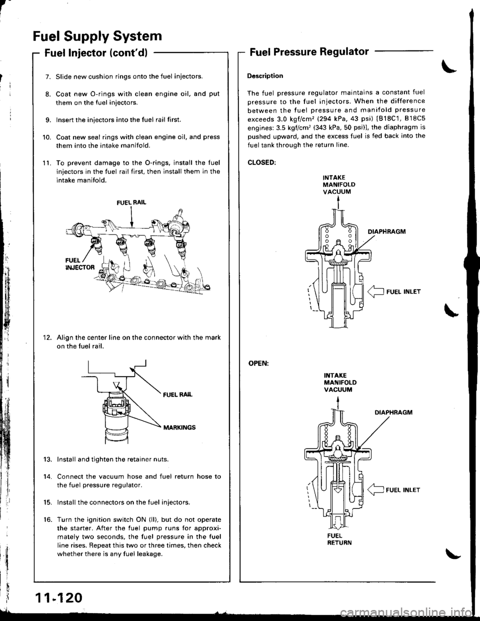
Description
The fuel pressure regulator maintains a constant fuel
pressure to the fuel injectors. When the difference
between the fuel pressure and manifold pressure
exceeds 3.0 kgf/cm'� (294 kPa,43 psi) IB18C'1,818c5
engines:3.5 kglcm'(343 kPa,50 psi)l, the diaphragm is
Dushed uDward, and the excess fuel is fed back into the
fuel tank through the return line.
CLOSED:
INTAKEMANIFOLDVACUUM
I1{TAKEMANIFOLDVACUUM
DIAPHRAGM
< IFUEL INLET\-
\
OIAPHRAGM
/4_\T-J FUEL INLET
9.
10.
11.
7.
8.
1t
Slide new cushion rings onto the fuel iniectors.
Coat new O-rings with clean engine oil, and put
them on the fuel injectors.
Insert the injectors into the fuel rail first.
Coat new seal rings with clean engine oil, and press
them into rhe intake manifold.
To prevent damage to the O-rings, install the luel
injectors in the fuel rail first, then install them in the
intake manifold.
Align the center line on the connector with the mark
on the fuel rail,
FUEL RAIL
MARKINGS
13.
14.
15.
16.
Install and tighten the retainer nuts.
Connect the vacuum hose and fuel return hose to
the fuel pressure regulator.
lnstall the connectors on the fuel injectors.
Turn the ignition switch ON (ll). but do not operate
the starter. After the fuel pump runs for approxi'
mately two seconds, the fuel pressure in the fuel
line rises. Repeat this two or three times, then check
whether there is any fuel leakage.
FUEL RAIL
FUEL
Page 326 of 1681
Testing
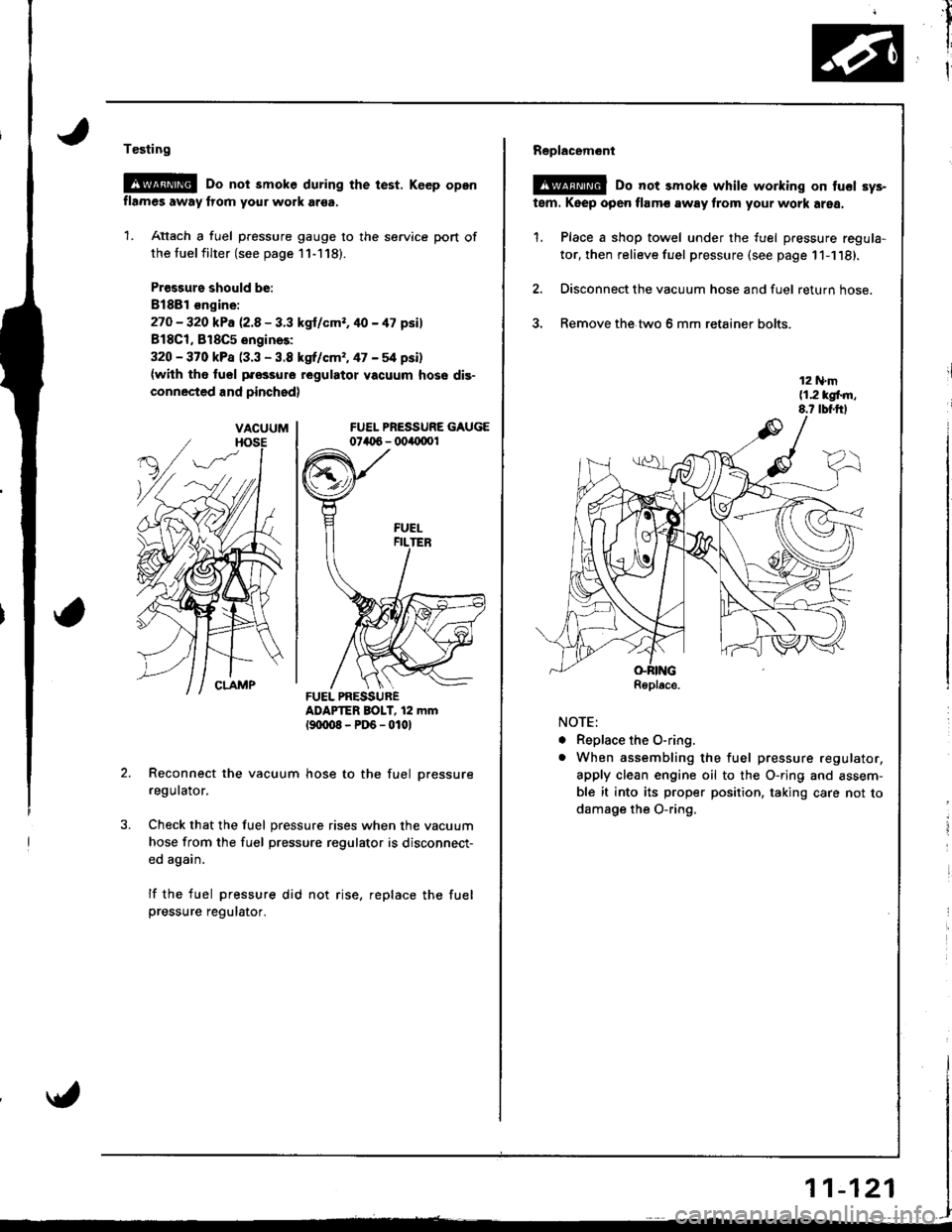
@G Do not smoke during the test. Keep opon
flames away lrom your work ar€a.
1. Attach a fuel pressure gauge to the service port of
the tuel filter (see page 11-118).
Pr€ssurs should be:
8188l €ngine:
27O - 320 kPa 12.8 - 3.3 kgl/cmr. 40 - 47 psil
818C1, 818C5 engines:
320 - 370 kPa (3.3 - 3.8 kgrf/cm,, 47 - 54 psi)
{with tho fuol pfossure regulatot vacuum hose dis-
connected and pinchsd)
FUEL PRESSURE GAUGE074t 6 - 004{1001
ADAPTER BOIT, 12 mm(9txt08-PD6-0101
Reconnect the vacuum hose to the fuel pressure
regulator.
Check that the fuel pressure rises when the vacuum
hose from the fuel pressure regulator is disconnect-
ed again.
lf the fuel pressure did not rise, replace the fuelpressure regulator.
VACUUM
FUEL PRESSURER€place.
AA
,il
I
I
Replacem6nl
@ Do not smoke while working on tucl sys-
tem. Keep open flamc away from your work area.
1. Place a shop towel under the fuel pressure regula-
tor, then relieve fuel pressure (see page 11-1'18).
2. Disconnect the vacuum hose and fuel return hose.
3. Remove the.two 6 mm retainer bolts.
NOTE:
. Replace the O-ring.
o When assembling the fuel pressure regulator,
apply clean engine oil to the O-ring and assem-
ble it into its proper position, taking care not to
damage the O-ring.
r1
i
i
11-121
Page 327 of 1681
rr*
Fuel Supply System
Fuel Filter
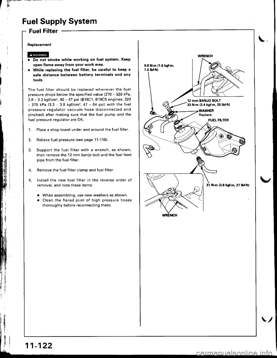
Replacement
Do not smoke while working on fuel system. Koop
open flame away from your work atea.
While replacing the fuel filter, be qaretul to keep a
sate distanco between battery terminals and any
tools.
The fuel filter should be replaced whenever the fuel
pressure drops below the specified value I27o - 32O kPa,
2.8 - 3.3 kgf/cm', 40 - 47 psi (B18C'1, B l8C5 enginesi 320- 370 kPa (3.3 - 3.8 kgtcm'�,47 - 54 psi) with the fuel
pressure regulator vacuum hose disconnected and
pinchedl aiter making sure that the tuel pump and the
fuel pressure regulator are OK.
Place a shop towel under and around the fuelfilter.
Relieve fuel pressure {see page 11-1'18}.
Support the fuel filter with a wrench, as shown,
then remove the 12 mm banjo bolt and the tuel feed
pipe lrom the fuelfilter.
Remove the fuel filter clamp and fuel filter.
lnstall the new fuel filter in the reverse order of
removal, and note these items:
. When assembling, use new washers as shown.
. Clean the tlared joint of high pressure hoses
thoroughly before reconnecting them.
\,,
9.8 N.m {1.0 kgf.m,7.2 tbf.frl
WRENCH
12 mm BANJO BOLT33 N.m 13.4 kgf.m. 25 lbl.ftl
37 N.m (3.8 kgf.m,27 lbf.ft)
Page 328 of 1681
'*
1i
v3
I
l
i
I
1.
Testing
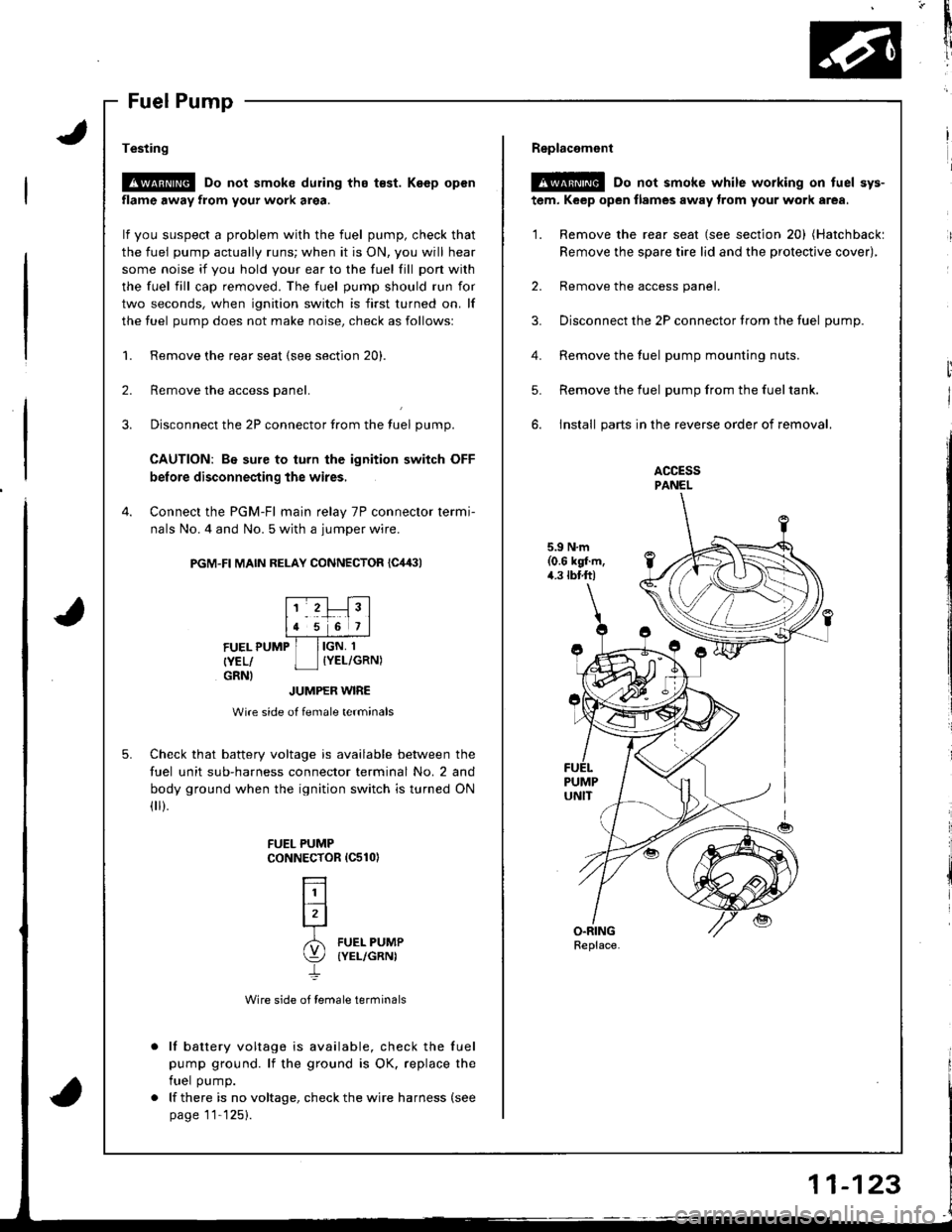
!@ Do not smoke during tho t€st. Keep open
flame away from your work area.
lf you suspect a problem with the fuel pump, check that
the fuel pump actually runs; when it is ON, you will hear
some noise it you hold your ear to the fuel fill pon with
the fuel fill cap removed. The fuel pump should run for
two seconds, when ignition switch is first turned on. lf
the fuel pump does not make noise, check as followsl
Remove the rear seat (see section 20).
Remove the access panel.
Disconnect the 2P connector from the tuel pump.
CAUTION: Be sure to turn the ignition switch OFF
before disconnecting the wires,
Connect the PGM-Fl main relay 7P connector termi-
nals No. 4 and No. 5 with a jumper wire.
PGM-FI MAIN RELAY CONNECTOR {C,14:}l
2.
3.
4.
5.
FUEL PUMP
{YEL/GRNI
IGN, 1
IYEL/GRN)
JUMPER WIRE
Wire side of female terminals
Check that battery voltage is available between the
fuel unit sub-harness connector terminal No. 2 and
body ground when the ignition switch is turned ON(
).
Wire side of female terminals
lf battery voltage is available, check the fuel
pump ground. lf the ground is OK. replace the
fuel pump.
lf there is no voltage, check the wire harness (see
page 11'125).
FUEL PUMPCoNNECTOR 1C510)
L]l
lrl-r
6l FUEL PUMP
\:/ (YEL/GRNI
4.
Replacemont
@ Do not smoke while working on tuel sys-
tem, Keep open flames away trom your work area.
'1. Remove the rear seat (see section 20) (Hatchbackl
Remove the spare tire lid and the protective cover),
2. Remove the access panel.
3. Disconnect the 2P connector trom the fuel oumD.
Remove the fuel pump mounting nuts.
Remove the fuel pump from the fueltank.
install parts in the reverse order of removal.
ACCESSPANEL
5.9 N.m(0.6 kgl.m,4.3 tbtft)
5.
Replace.
Page 329 of 1681
1L
i
!i
!
{
Fuel Supply System
PGM-Fl Main Relay
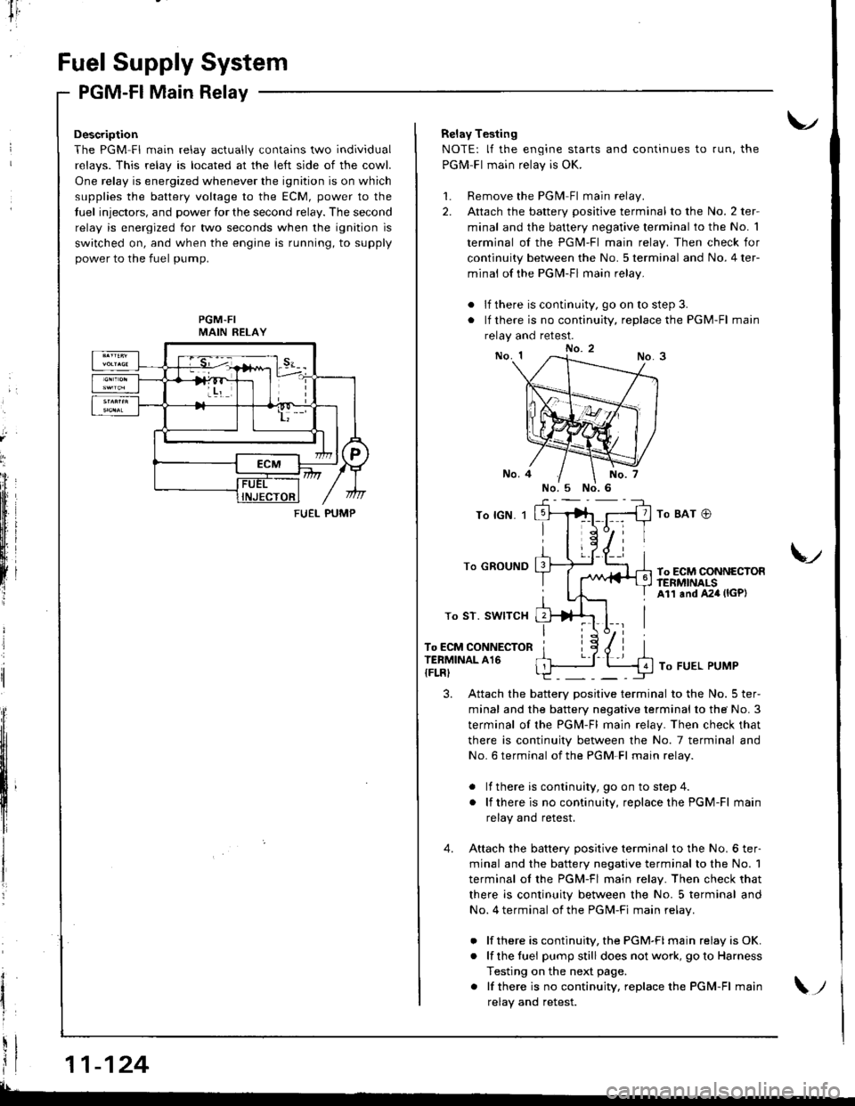
Description
The PGM Fl main relav actuallv contains two individual
relavs. This relav is located at the left side of the cowl.
One relay is energized whenever the ignition is on which
supplies the battery voltage to the ECM, power to the
tuel injectors, and power tor the second relay. The second
relay is energized for two seconds when the ignition is
switched on, and when the engine is running, to supply
power to the fuel pump.
PGM-FIMAIN RELAY
11-124
FUEI- PUMP
Relay Testing
NOTE: lf the engine starts and continues to run, the
PGM-Fl main relay is OK.
1. Remove the PGlvl Fl main relay.
2. Attach the battery positive terminal to the No. 2 ter-
minal and the battery negative terminal to the No. 1
terminal of the PGM-Fl main relay. Then check for
continuity between the No. 5 terminal and No. 4 ter-
minal of the PGN4-Fl main relay.
. lf there is continuity, go on to step 3.
. lf there is no continuity, replace the PGM-Fl main
relay and retest.
To lGN. 1
To GROUND
To ST. SWITCH
To ECM CONNECTORTERMINAL A16
{FLRI
To BAT @
To ECM CONNECTORftNMNALSAll and A24 (lGP)
V
To FUEL PUMP
3. Attach the battery positive terminal to the No. 5 ter-
minal and the battery negative terminal to the No. 3
terminal of the PGM-Fl main relay. Then check that
there is continuity between the No. 7 terminal and
No. 6 terminal of the PGM-Fl main relav.
. lf there is continuity, goon tostep4.
. lf thereis nocontinuity, replacethe PGM-Fl main
relay and retest.
4. Attach the batterv oositive terminal to the No. 6 ter-
minal and the battery negative terminal to the No. 1
terminal ol the PGM-Fl main relay. Then check that
there is continuity between the No. 5 terminal and
No. 4 terminal of the PGM-Fi main relav.
. lf there is continuity, the PGM-FI main relay is OK.
. lf the fuei pumpstill does not work, goto Harness
Testing on the next page.
. lf thereis nocontinuity, replacethe PGM-Fl main
relav and retest.\;
Page 330 of 1681
I
tr,
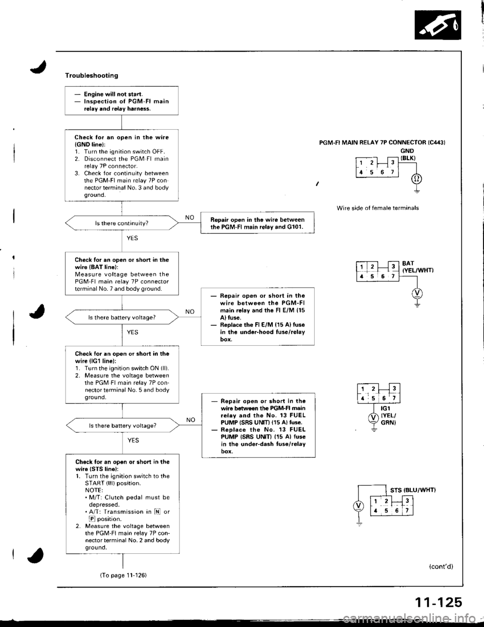
- Engine will not start.- Inspection of PGM-FI mainrelay and relay harne$.
Check lor an open in the ware{GND line}l1. Turn the ignition switch OFF.2. Disconnect the PGM Fl mainrelay 7P connector.3. Check for continuity betweenthe PGM'FI main relay 7P connector terminal No. 3 and bodyground,
Repair open in the wire betweenthe PGM-Fl main relay and G101.
Check for an open or shon in thewire {BAT line)rMeasure voltage between thePGM-Fl main relay 7P connectorterminal No.7 and body ground.- Fepaii open or short in thewire between the PGM-FImain rel6y and the Fl E/M 115A) tuse.- Replace th€ Fl E/M {15 A)fusein the under-hood tuse/relay
ls there battery vohage?
Check foi an open or shori in thewire (lG1 line):1. Turn the ignition switch ON (ll).
2, Measure the voltage betweenthe PGM Fl main relay 7P con-nector terminal No. 5 and bodyground,R€pair open or short in thewire betwo€n the PIGM-FI mainrelav and the No. 13 FUELPUMP ISRS UNIT) (15 Altuse.ReDlace the No. 13 FUELPUMP ISRS UNID (15 Al fusein the under-dash tuse/relayoox,
Check for an open or short in thewire {STS linel:1. Turn the ignition switch to theSTART { lll) position.NOTE:. M/T: Clutch pedal must beoepresseo.. A/T: Transmission in ld or
E position.2. Measure the voltage betweenthe PGM-FI main relay 7P con-nector terminal No. 2 and bodyground,
Troubleshooting
'l RELAY 7P CONNECTOR
GND
t .--.-l T;-l IBLK)L' 'r I" T----
lr s o rl A
+
Wire side o{ female termanals
8AT(YEL/WHT)
STS {BLU/WHTI
(cont'd)
(To page11- t 26)
11-125