HONDA INTEGRA 1998 4.G Workshop Manual
Manufacturer: HONDA, Model Year: 1998, Model line: INTEGRA, Model: HONDA INTEGRA 1998 4.GPages: 1681, PDF Size: 54.22 MB
Page 771 of 1681
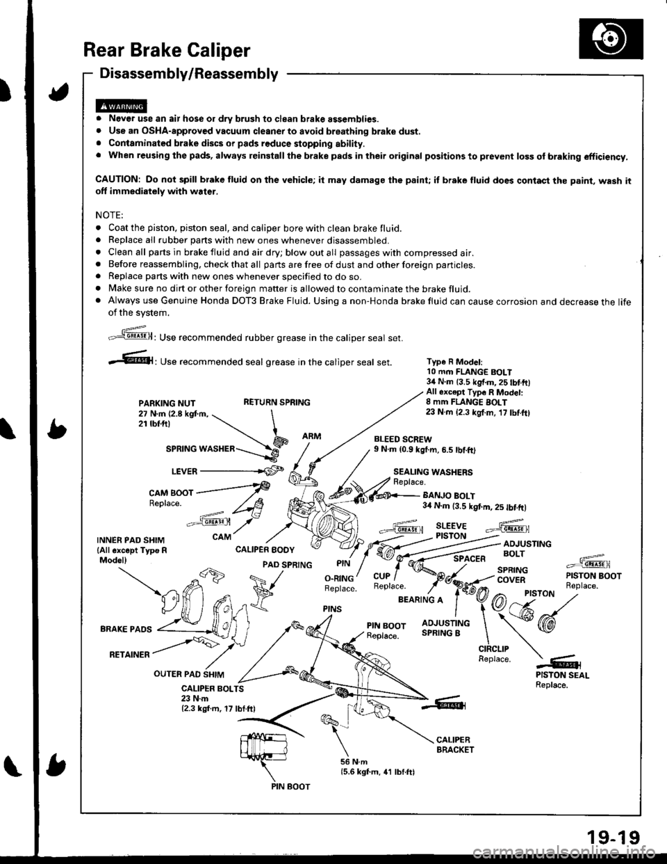
Rear Brake Caliper
Disassembly/Reassembly
o Never use an air hose or dry brush to clean brake assemblies.o Use an OSHA-approv€d vacuum cleaner to avoid breathing brake dust.. Conlaminated brake discs or pads reduce stopping ability.. When reusing the pads, always reinstall the brake pads in their original positions to prevent loss of braking efficiency,
CAUTION: Do not spill brake fluid on the vehicle; it may damags the paint; it brake fluid does contast the paint, wash itoff immediately with water,
NOTE:
. Coat the piston. piston seal, and caliper bore with clean brake fluid.. Beplace all rubber parts with new ones whenever disassembled.o Clean all parts in brake fluid and air dry; blow out all passages with compressed air.a Before reassembling, check that all parts are free of dust and other foreign particles.
. Replace parts with new ones whenever specified to do so.. Make sure no dirt or other foreign matter is allowed to contaminate the brake fluid.. Always use Genuine Honda DOT3 Brake Fluid. Using a non-Honda brake fluid can cause corrosion and decrease the lifeof the svstem.
Type R Model:10 mm FLANGE BOLT34 N.m 13.5 kg{.m,25 tbtftlAll 6xc€pt Typ6 R Modet:8 mm FLANGE BOLT23 N.m {2.3 kgf.m, 17 tbf.ft)
BANJO BOLT3,0 N.m (3.5 kgt m, 2s tbtftl
Replace.
;,'"]@: Use recommended rubber grease in the caliper seal set.
.61, Use recommended seal grease in the catiper seal set.
PARKING NUTRETURN SPRING
27 N.m 12.8 kgt m, \2rtbt.frl \
ar"t"o *or"a"=-\9_r.r,e=
LEVER -------rCF
c^M Boor ---f
Re'lace
-==': /t8
"':sst /-
CALIPER BOLTS23 N.m12.3 kgf.m, 17 lbf.ft)
TNNERPADSHTM cAM
lAll except Typs R CALIPER EODYModel)
OUTER PAO SHIM
-db
PAD SPRTNG
a71 ^ V
BRAKEPA''
vUffifi*
,*,
^rrorr /Y'
,/ ^,
O.RINGBeplace.
PINS
BLEED SCREW9 N.m (0.9 kg{.m, 6.5 tbf.ft)
SEALING WASHERSReplace.
PIN BOOT
Page 772 of 1681
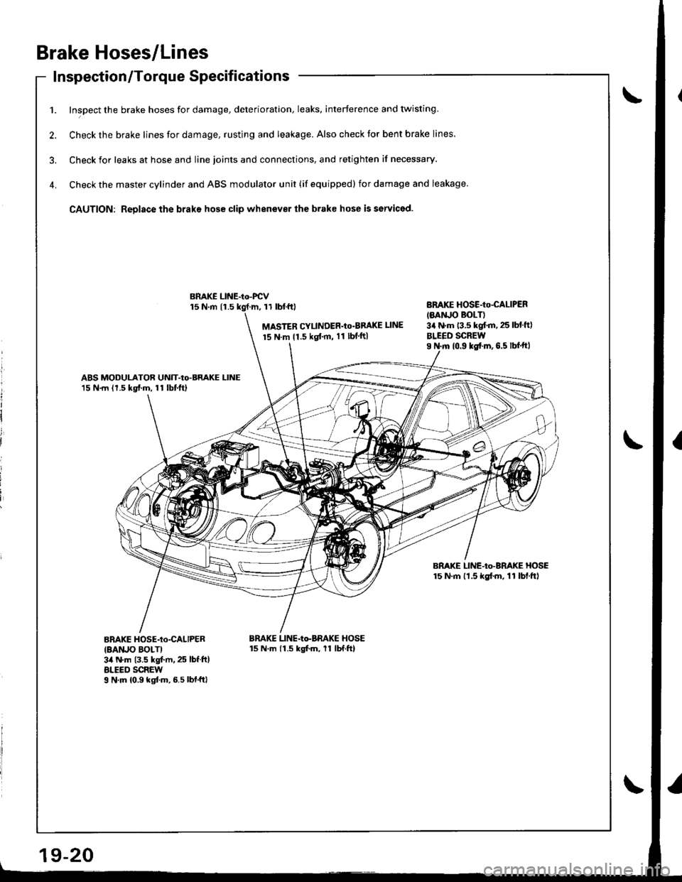
Brake Hoses/Lines
Inspection/Torque Specif icationsInspecuon/ | orque Dpecl carlon
1. Inspect the brake hoses for damage, deterioration, leaks, interference and twisting
2. Check the brake lines for damage, rusting and leakage. Also check tor bent brake lines.
3. Check ior leaks at hose and line joints and connections, and retighten if necessary.
4. Check the master cylinder and ABS modulator unit (if equipped) for damage and leakage.
CAUTION: Replace the braks hose clip whenever the brake hose is serviced.
15 N.m 11.511 tbl.f0
MASTER CYLINDER'Io'BBAKE UNE
15 N.m {1.5 kgt'm, 11 lbf ft}
BnAKE HOSE-Io-CALIPER
IMNJO BOLTI3a N'm 13.5 kgf.m. 25 lbl ft)
BLEED SCREWI N.m 10.9 ks{.m,6.5 lbf.ftl
ABS MODULATOR UNIT-Io-BRAKE LINE15 N.m (1.5 kg{.m, 11 lbtftl
BRAKE LINE-Io-BRAKE HOSE15 N'm lt.5 kgf.m, 11 lbf.ftl
BnAKE HOSE-Io-CALIPER
IBAruO BOLTI3il N.m (3.5 kgt m, 25 lbf.ft)ALEED SCREWI N'm 10.9 kgtm,6.5lbf.ftl
BRAKE LINE-Io-BRAKE HOSE15 N.m 11.5 kgfm, 11 lbf.ftl
BMKE LINE-Io-FCV
l
It
I
i
i
i
Page 773 of 1681
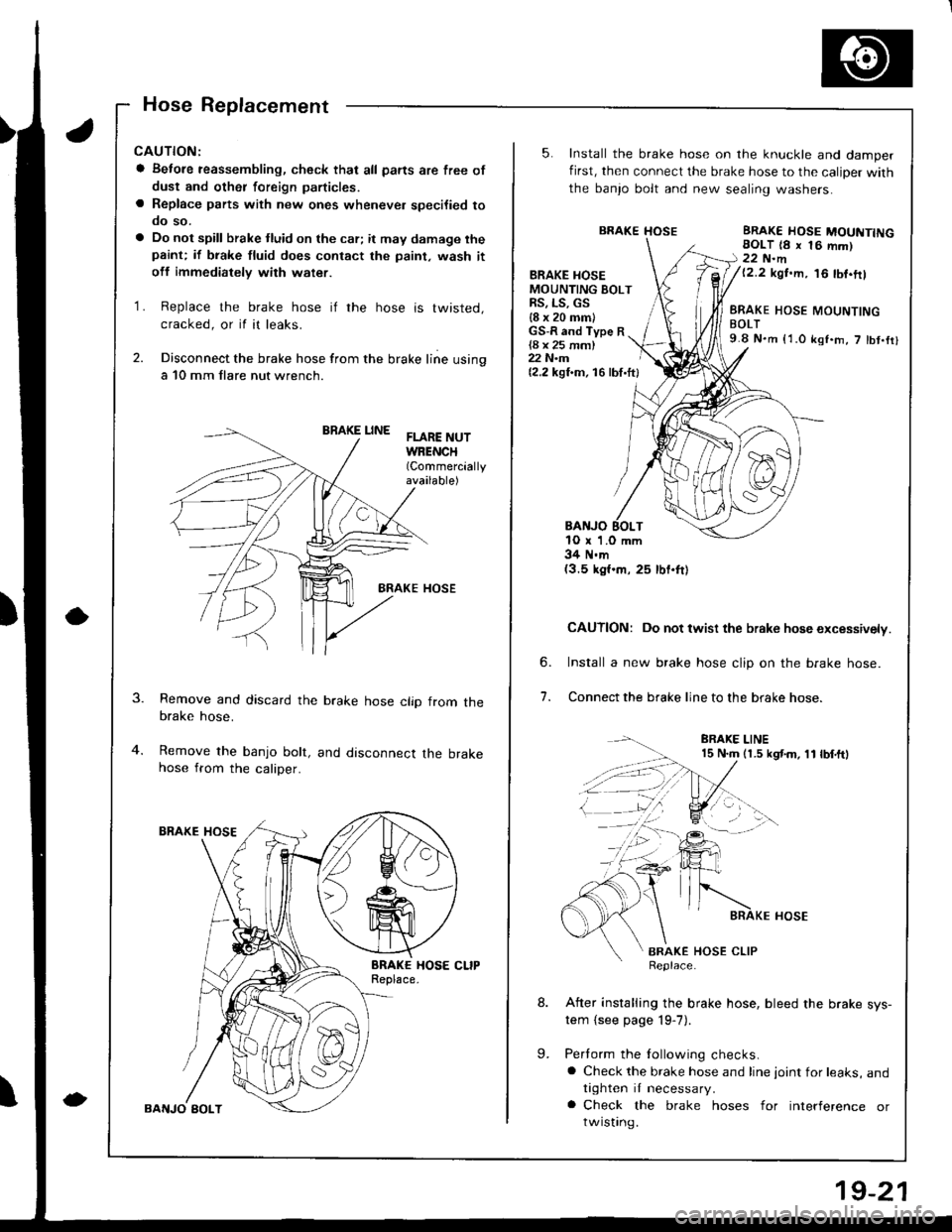
Hose Replacement
CAUTION:
a Betore reassembling, check thal all parts are free of
dust and othet foreign particles.
a Replace parts with new ones whenever specilied tooo so.
a Do not spill brake tluid on the car; it may damage thepaint; if biake fluid does contact the paint, wash it
off immediatelv with water.
1. Replace the brake hose if the hose is twisted,
cracked, or il ir leaks.
2. Disconnect the brake hose from the brake line using
a 10 mm llare nut wrench.
BRAKE LINEFLARE NUTWRENCH(Commercially
available)
BRAKE HOSE
Remove and discard the brake hose clip from thebrake hose.
Remove the banjo bolt, and disconnect the brakehose from the caliper.
5.
BRAKE HOSEMOUNTING BOLTRS, LS, GS{8 x 20 mm)
Install the brake hose on the knuckle and damper
first, then connect the brake hose to the caliDer with
the banjo bolt and new sealing washers.
BRAKE HOSEERAKE HOSE MOUNTINGEOLT 18 x 16 mm)22 N.m{2.2 kgt.m, 16 tbf.ftl
GS-R and Type R{8 x 25 mm)22 N.m(2,2 kgf.m, 16lbf.ftl
BANJO EOLTtO r 1.0 mm34 N.m(3.5 kgf.m, 25 lbf.ft)
CAUTION: Do not twist the brake hose excessively.
Install a new brake hose clip on the brake hose.
Connect the brake line to the brake hose.
6.
7.
BRAKE HOSE MOUNTINGBOLT9.8 N.m {'1.0 kst.m, 7 tbt.fi}
BRAKE LINE15 N.m (1.5 kgt m, 11 lbf.ftl
BRA(E HOSE CLIPReplace.
After installing the brake hose, bleed the brake sys-tem (see page 19-7).
Perlorm the following checks.a Check the brake hose and line joint for leaks, andtighten it necessary.
a Check the brake hoses for interference orrwrslrng.
.:2-.--l
L
19-21
Page 774 of 1681
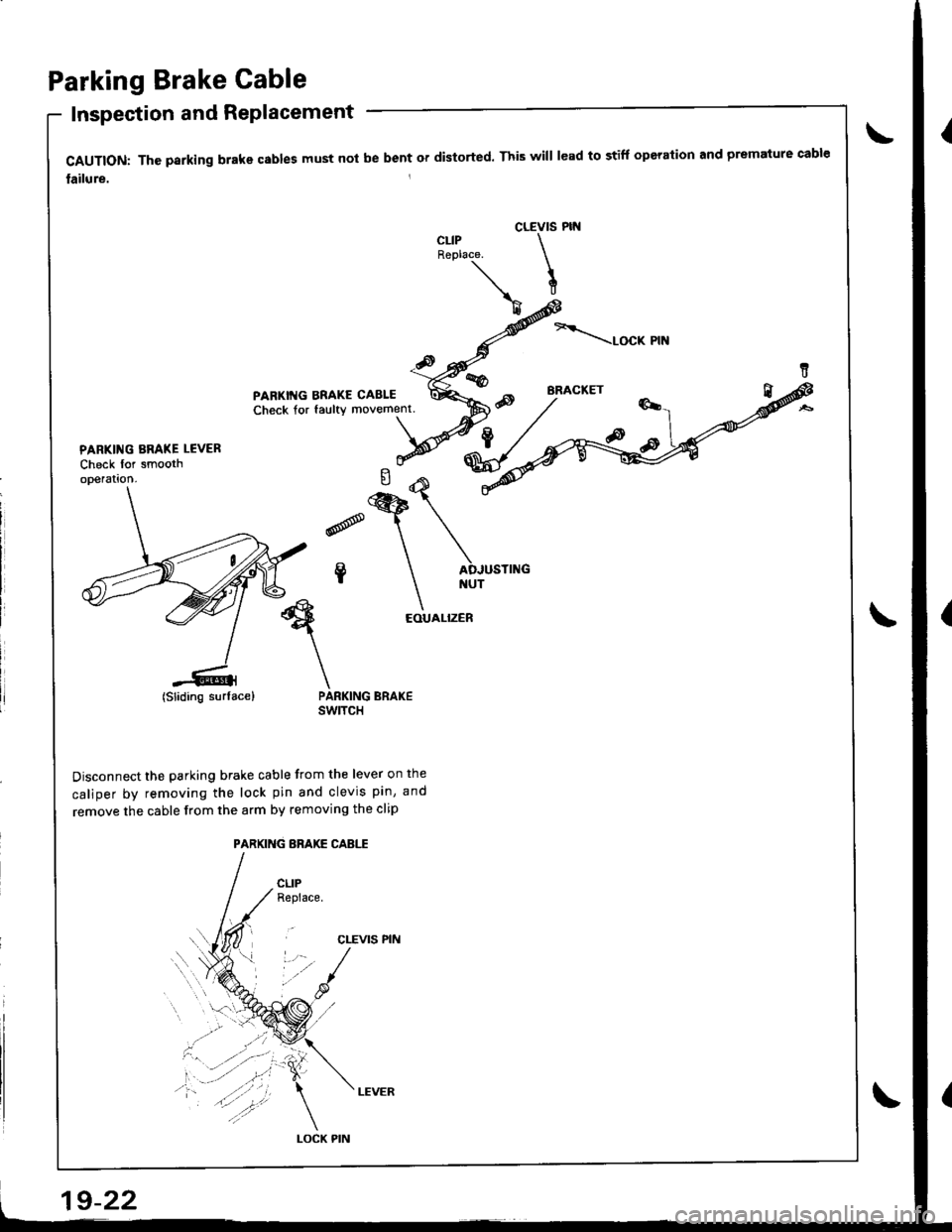
Parking Brake Cable
Inspection and Replacement
CAUTION: Thc psrking brake cables must not be bent or distorted. This will lead to stiff operation and premature cable
lailure.
CLEVIS PIN
LOCK PIN
PARKING ERAKE LCVER
Check for smooth
EOUALIZER
(Sliding surface) PARKING BRAKEswtTcH
Disconnect the parking brake cable from the lever on the
caliper by removing the lock pin and clevis pin, and
remove the cable from the arm by removing the clip
PARKING BRAKE CABLE
CLEVIS PIN
CLIPReplace.
lSliding surlace)
19-22
Page 775 of 1681
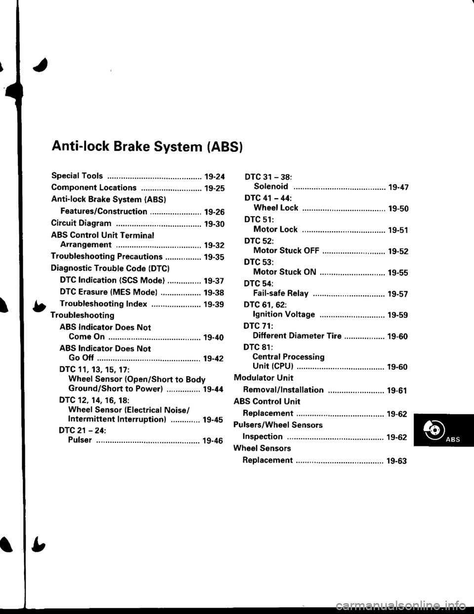
Anti-lock Brake System {ABS}
Speciaf Tools ............... 19-24
Component Locations,...........,..,........... 19-25
Anti-lock Brake System (ABSI
Features/Construction ....................... 19-2G
Circuit Diagram ........... 19-30
ABS Control Unit Terminal
Arrangement ........... 19-32
Troubleshooting Precautions ................ 1g-35
Diagnostic Trouble Code (DTC)
DTC Indication (SCS Mode) ............... t9-37
DTC Erasure {MES Mode) .................. 19-38
b Troubleshooting Index ...................... 19-39- Troubleshooting
ABS Indicator Does Not
Come On .............. 19-40
ABS Indicator Does Not
Go Off .............. ..... 19-42
DTC 11, 13, 15. 17:
Wheel Sensor (Open/Short to Body
Ground/Short to Power) ............... l9-44
DTC 12. 14, 16, 18:
Wheel Sensor (Electrical Noise/
Intermittent Interruption) ..........,.. 19-45
DTC21 -24:
Pulser ...,.......... ..... 19-46
DTC 31 - 38:
Solenoid .............. 19-47
DTC 41 - 44:
Wheel Lock .......... 19-50
DTC 51:
Motor Lock .......... 19-51
DTC 52:
Motor Stuck OFF ...................,........ 19-52
DTC 53:
Motor Stuck ON ............................. 19-55
DTC 54:
Fail-safe Relay ................................ t9-57
DTC 61.62:
lgnition Voltage ............................. 19-59
DTC 71:
Different Diameter Tire .................. 1 9-60
DTC 81:
Gentral Processing
Unit {CPU} ............ 19-60
Modulator Unit
Bemoval/lnstallation ......................... 19-61
ABS Control Unit
Replacement ............ 19-62
Pulsers/Wheel Sensors
Inspection ................ 19-62
Wheel Sensors
Replacement .,.......... 19-63
Page 776 of 1681
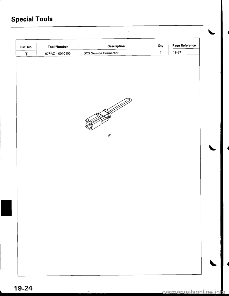
Special Tools
ReI. No. Tool Numbe;
07PAZ - 0010100
19-24
Page 777 of 1681
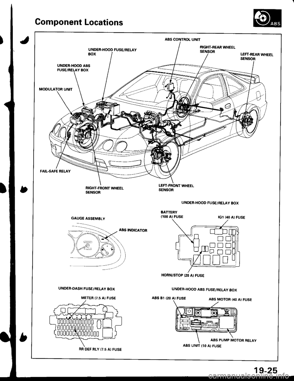
Gomponent Locations
,)
ABS CONTROL UNIT
UNDER.HOOD FUSE/RELAYRGHT-NEAR WHEELsEillioRaoxLEFT.REAR WHEEI-SENSOR
UNDER-H(X)D ABS
MODULATOR UNIT
FAIL-SAFE RELAY
RIGHT-FRONT WHEELSENSOR
LEFT-FROl{T WHEELSENSOR
UNDER.HOOD FUSE/RELAY BOX
ABS INDICATOR
UNDER.HOOD ABS FUSE/RELAY 8OX
ABS 81 {20 AI FUSEAAS MOTOR {40 Al FUS€
AAS PUMP MOTOR RELAY
GAUGE ASSEMBLY
!D
Dtrt]
HORN/STOP I2O A) FUSE
A8S UNIT {10 AI FUSERR DEF FI-Y I7.5 AI FUSE
19-25
Page 778 of 1681
.,i
,I
Anti-lock Brake SYstem (ABS)
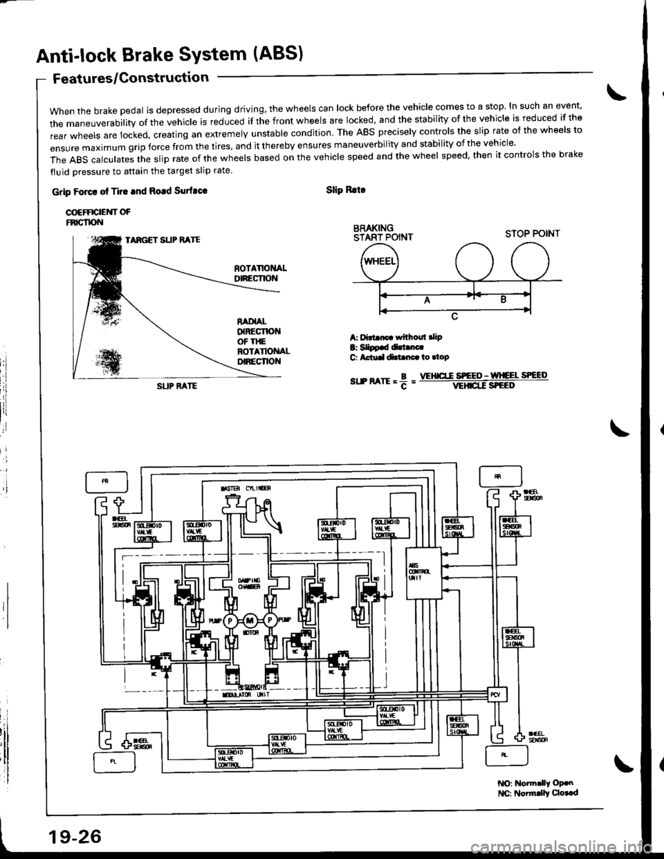
when the brake pedal is depressed during driving, the wheels can lock before the vehicle comes to a stop. In such an event.
the maneuverability of the vehicle is reduced if the front wheels are locked, and the stability of the vehicle is reduced if the
rear wheels are locked, creating an extremely unstable condition. The ABS precisely controls the slip rate o{ the wheels to
ensUre maximum grip force from the tires, and it thereby ensures maneuverbiIity and stabiIity of the vehicIe.
The ABS calculates the slip rate of the wheels based on the vehicle speed and the wheel speed. then it controls the brake
fluid oressure to attain the target slip rate
Features/Gonstructio n
Grip Foact ot Ti.c tnd Rotd Surfuco
COEFFICIEUT OFFNIG"TPN
Slip Rrtr
BRAKINGSTART POINT
i'l
A: f'3t rp withoul .lip
B: SIDp.d dirt.nc.G Actu.ldtt nc.io.top
sr.n arrr = f =
STOP POINTTARGET SUP RATE
SUP FATEVEHICT.C S'EEO - wlCEL SPEED
NO: Notm.lly oP.n
l{C: Noirnrly qo..d
19-26
Page 779 of 1681
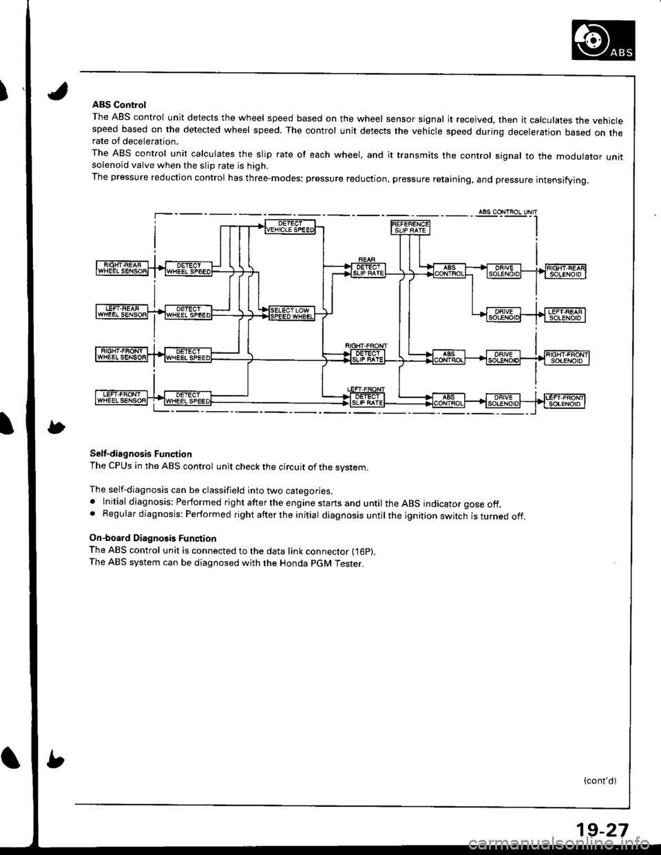
IABS Control
The ABS control unit detects the wheel speed based on the wheel sensor signal it received, then it calculates the vehiclespeed based on the detected wheel speed. The control unit detects the vehicle speed during deceleration based on therate of deceleration.
The ABS control unit calculates the slip rate of each wheel, and it transmits the control signal to the modulator unitsolenoid valve when the slip rate is high.
The pressure reduction control has three-modes: pressure reduction, pressure retaining, and pressure intensifying.
Self-diagnosis Function
The CPUS in the ABS control unit check the circuit of the system.
The self-diagnosis can be classifield into two categories.. Initial diagnosis: Performed right after the engine starts and until the ABS indicator gose off.. Regular diagnosis: Performed right after the initial diagnosis until the ignition switch isturnedoff.
On-board Diagnosis Function
The ABS control unit is connected to the data link connector fi6p).The ABS system can be diagnosed with the Honda PGM Tester.
(cont'd)
19-27
Page 780 of 1681
Anti-lock Brake System (ABS)
Features/Construction (cont'd)
ABS Modulatol
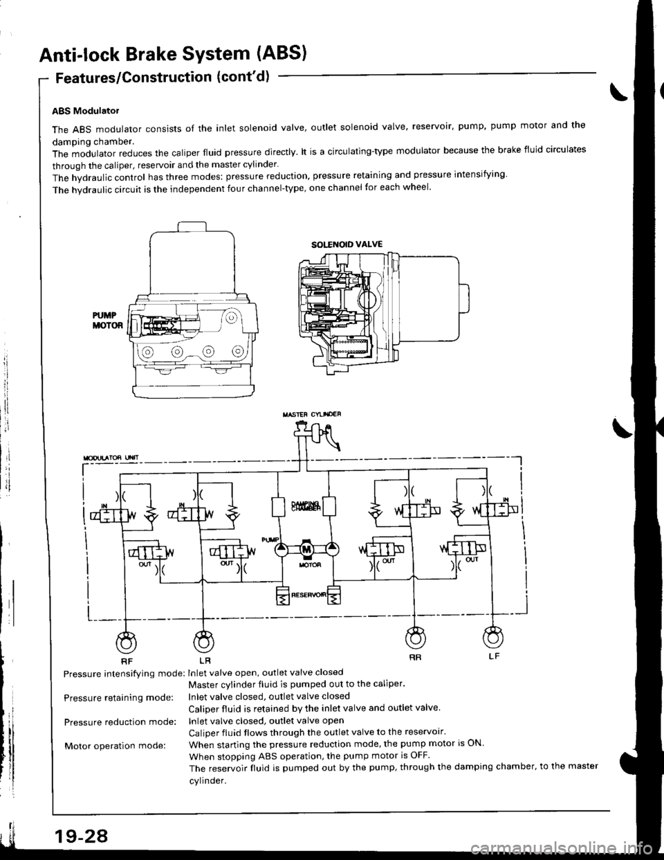
The ABS modulator consists of the inlet solenoid valve, outlet solenoid valve, reservoir, pump, pump motor and the
damping chamber.
The modulator reduces the caliper fluid pressure directly. lt is a circulating-type modulator because the brake fiuid circulates
through the caliper, reservoir and the master cylinder.
The hydraulic control has three modes: pressure reduction, pressure retaining and pressure intensiiying
The hvdraulic circuit is the independent four channel-type, one channel tor each wheel'
L-__
RF LR
Pressure intensifying mode: Inlet valve open, outlet valve closed
Master cvlinder fluid is pumped out to the caliper.
Inlet valve closed, outlet valve closed
Caliper fluid is retained by the inlet valve and outlet valve.
lnlet valve closed, outlet valve open
Caliper fluid flows through the outlet valve to the reservolr'
When starting the pressure reduction mode, the pump motor is ON.
When stopping ABS operation, the pump motor is OFF.
The reservoir fluid is pumped out by the pump, through the damping chamber, to the master
cylinder.
\
Pressure retaining mode:
Pressure reduction mode:
Motor operation mode:
sott orD vALvE
@@-@@
TASIEF CYLI'OEF
19-24