HONDA INTEGRA 1998 4.G Workshop Manual
Manufacturer: HONDA, Model Year: 1998, Model line: INTEGRA, Model: HONDA INTEGRA 1998 4.GPages: 1681, PDF Size: 54.22 MB
Page 761 of 1681
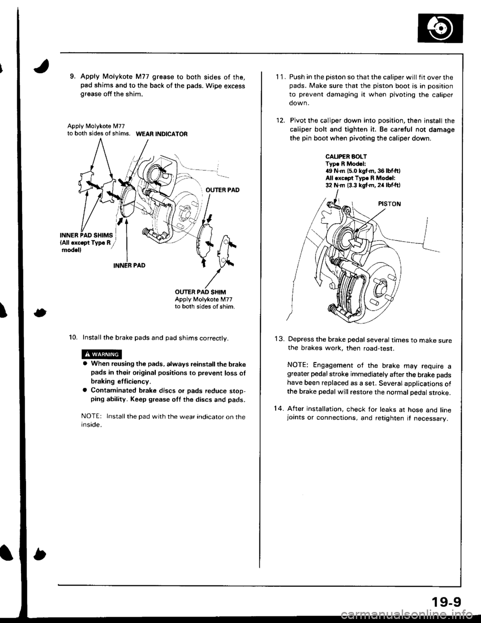
9. Apply Molykote M77 gresse to both sides of the,pad shims and to the back of the pads. Wipe excessgrease off the shim,
Apply N4olykote M77to both sides ot shims. WEAR |ND|CATOR
OUTER PAD
INN
\
ER,
OUTER PAD SHIMAppty Motykote M77to both sides of shim,
10. Install the brake pads and pad shims correctly.
a When reusing the pads, always reinstall the brakepads in their original positions to prevent loss of
braking etficiency.
a Contaminated btake discs ot pads reduce stop,ping ability. Keep grease oft the discs and pads.
NOTE: lnstall the pad wilh the wear indicator on theinside.
11.
14.
Push in the piston so that the caliper will fit over thepads. Make sure that the piston boot is in position
to prevent damaging it when pivoting the caliper
down.
Pivot the caliper down into position, then install the
caliper bolt and tighten it. Be careful not damage
the pin boot when pivoting the caliper down.
CAUPER AOLTTyp. R Mod.l:4!, N.m (5.0 kgl.m,36lbtft)All .xc.pt Typ. R Modcl:32 N.m 13.3 kgf.m,24 lbf.ftl
13.Depress the brake pedal several times to make surethe brakes work, then road-test.
NOTE: Engagement of the brake may require agreater pedal stroke immediately after the brake pads
have been replaced as a set. Several aDplications ofthe brake pedal will restore the normal pedal stroke.
After installation, check for leaks at hose and linejoints or connections, and retighten it necessary.
19-9
Page 762 of 1681
Front
Disc
Brake
Runout
Disc
InspectionDisc Thickness and Parallelism
\'L
2.
Loosen the front wheel nuts slightly, then raise the
vehicle and suppon it on safety stands. Remove the
front wheels.
Remove the brake pads (see page 19-8).
Inspect the disc surface for damage or cracks. Clean
the disc thoroughly and remove all rust.
Use wheel nuts and suitable plain washers to hold
the disc securely against the hub, then mount a dial
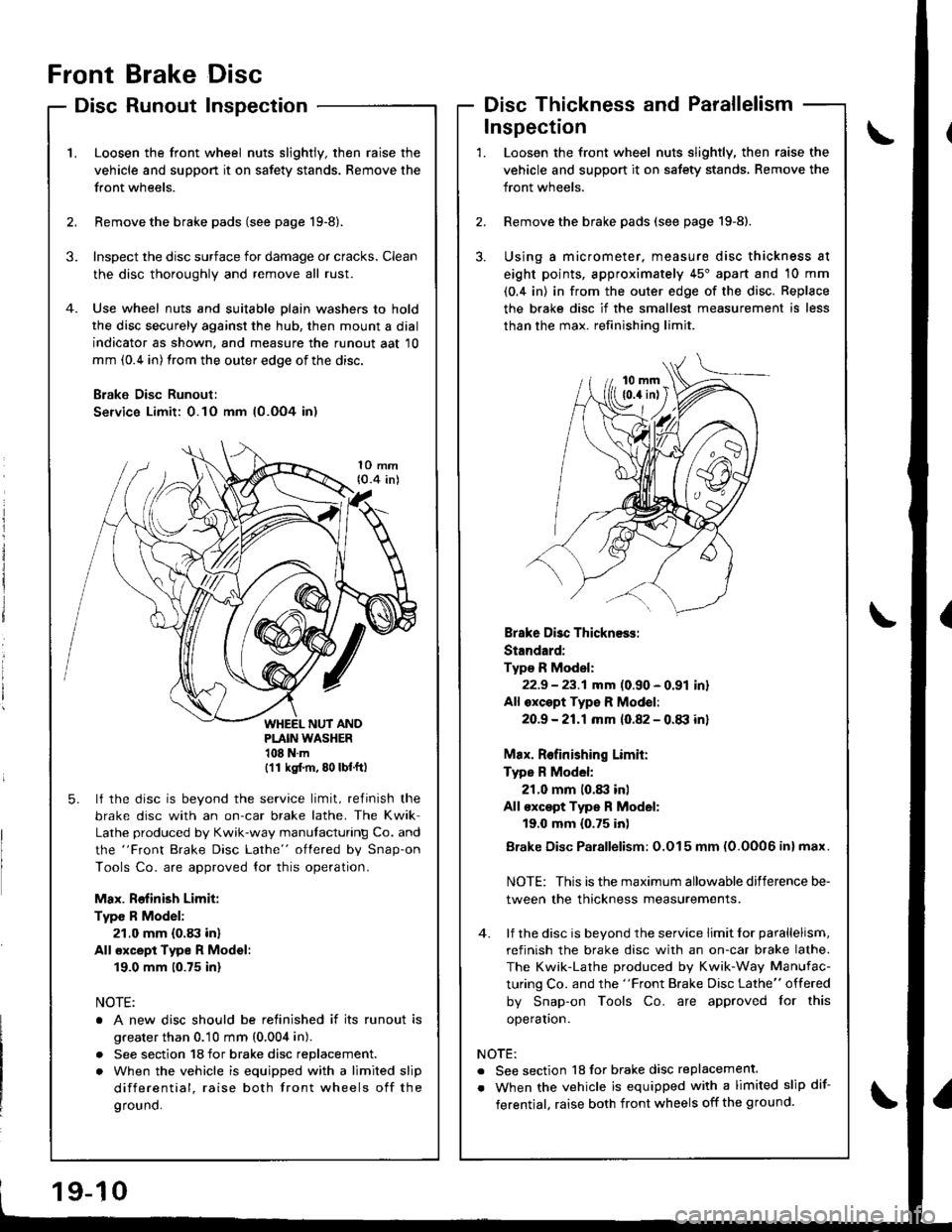
indicator as shown, and measure the runout aat 10
mm (0.4 in) from the outer edge of the disc.
B;ake Disc Runoul:
Service Limit: 0.10 mm (0.OO4 in)
3.
1O mm{0.4 inl
PLAIN WASHER108Nm(11 ksl.m, 80 lbf.ft)
5. lf the disc is beyond the service limit, refinish the
brake disc with an on-car brake lathe. The Kwik
Lathe produced by Kwik-way manutacturing Co. and
the "Front Brake Disc Lathe" oflered by Snap-on
Tools Co. are approved {or this operation.
Max. Rofinish Limit:
Type R Model:
21.0 mm (0.83 in)
All €xcept Type R Model:
19.0 mm (0.75 inl
NOTE:
o A new disc should be relinished if its runout is
greater than 0.10 mm (0,004 in).
. See section 18 for brake disc replacement.
. When the vehicle is equipped with a limited slip
differential, raise both front wheels off the
ground.
3.
Loosen the front wheel nuts slightly, then raise the
vehicle and support it on safety stands, Remove the
front wheels.
Remove the brake pads (see page 19-8).
Using a micrometer, measure disc thickness at
eight points, approximately 45'apart and 10 mm
(0.4 in) in from the outer edge of the disc. Replace
the brake disc if the smallest measurement is less
than the max. refinishing limit.
Inspection
2.
1.
Brake Disc Thickness:
Standard:
Type R Model:
22.9 - 23.1 mm (0.90 - 0.91 inr
All oxcept Typ€ R Mod€l:
2O.9 -21.1mm 10.82 - 0.tB inl
Max. Relinishing Limit:
Type R Model:
21.0 mm 10.83 inl
All €xc€pt Type R Model:
19.0 mm {0.75 inl
Brake Disc Parallelism: O.O15 mm (0.0006 inl max.
NOTE: This is the maximum allowable difference be-
tween the thickness measurements.
4. lf the disc is beyond the service limit lor parallelism,
refinish the brake disc with an on-car brake lathe.
The Kwik-Lathe produced by Kwik-Way Manufac-
turing Co. and the "Front Brake Disc Lathe" offered
by Snap-on Tools Co. are approved for this
operaton.
NOTE:
. See section 18 for brake disc replacement.
. When the vehicle is equipped with a limited slip dif-
ferentjal, raise both front wheels off the ground.
Page 763 of 1681
Front Brake Caliper
Disassembly/Reassembly
. Never use an air hoss or dry brush to claan b.ake assemblies.. Use an OsHA-approvod vacuum cleane. to avoid breathing braks dust,. Contaminated brake discs or pads roduce stopping ability.. When rausing tha pads. always rein3tall the brake p8d3 in thoir original positions to prevont loss of braking etticlency.
GAUTION: Do not spill brake fluid on the vehicle; it may damags the paint; it brake fluid do6s contast the paint, wash hoff imm€diately with wator.
NOTE:
. Coat the piston, piston seal, and caliper bore with clean brake fluid.. Replace all rubber pans with new ones whenever disassembled,. Clean all pans in brake fluid and air dry; blow out all passages with compressed air,. Before reassembling, check that all parts are free of dust and other foreign particles.
. Replace parts with new ones whenever specified to do so.. Make sure no din or other foreign matter is 8llowed to contaminate the br8ke fluid.. Always use Genuine Honda DOT3 Brake Fluid. Using non-Honda brake fluid can caus6 corrosion and d€crease the liftof the system.
ffl; Use recommended rubber grease in the caliper seal set.
.61, Use recommended seal grease ,n the caliper seal set.
All except Type R Model:
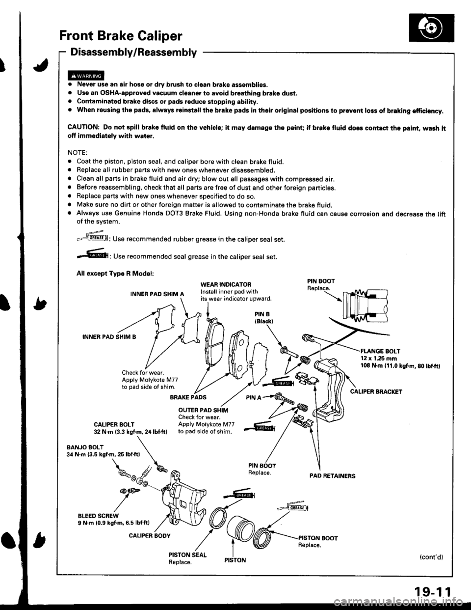
INNER PAD SHIM A
BRAKE PADS
OUTER PAD SHIMCheck for wear.CALIPER BOLT Apply Molykote M7732 N.m {3.3 kgf.m, 2,1 lbtftl to pad side of shim.
WEAR INDICATORInstall inner pad withits wear ;ndicator upward.
nh/t I
T)2
,V--6&,
PAD RETAINERS
'12 x 1.25 mm108 N.m (r1.0 kgl.m.80 tbtftl
CALIPER BMCKET
{cont'd)
PIN BOOT
PIN 8
INNER PAD SHIM B
BANJO BOLT3a N.m {3.5 kgf.m, 25 lbf.ftl
Check for wear.Apply Molykote M77to pad side of shim.
,\
kw
/":^
19-1 1
Page 764 of 1681
Front Brake Caliper
Disassembly/Reassembly (cont'd)
@o ?,lever use an air hosg qr dry brush to clean brake asaemblies.
o Use an OSHA-approved vacuum cleanor to avoid breathing braks du3t.
. Contaminatod brake disca or pads rsduce stopping sbility.
. Whan reusing the pads, alvyays reinstall the brake pads in their original pGitions to provent lo$ of braking etficiency'
CAUTION: Do not spitl brake fluid on the vohicle; h may damage tho paini; il btake tluid does contact the paint, wash it
off immediately with water.
NOTE:
. Coat the piston, piston seal, and caliper bore with clean brake fluid.
. Replace all rubber parts with new ones whenever disassembled.
. Cleanall parts in brake fluid and 8ir dry; blow out all passages with compressed air.
. Before reassembling, check that all parts are free of dust and other foreign particles.
. Replace parts with new ones whenever specified to do so.
. Make sure no din or other foreign matter is allowed to contaminate the brake fluid.
. Always use Genuine Honda DOT3 Brake Fluid. Using a non-Honda brake fluid can cause corrosion and decrease the liJe
of the system.
.ff: Use recommended rubber grease in the caliper seal set.
.6|lruse recommended seal grease in the caliper seal set.
Typs R Modol:
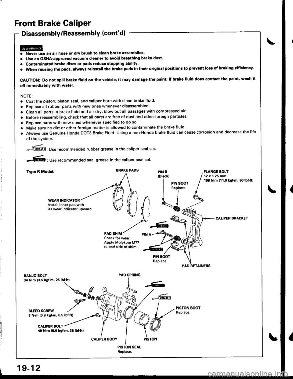
WEAR II{DICATORInstall inner pad withits we6r indicator upward.
PAD SHIM
PISTON EOOTReplace.
ARAKE PADSFLANGE BOLT12 r 1.25 mmlO8 N.m 111.O kgl.m, 80 lbf.ftl
CAUPER ARACKET
Ch€ck for wear.Apply Molykote M77to pad side of shim.
BANJO BOLT34 .m 13.5 kgt.m, 25 lbf'ft|
BLEEO SCREWs N.n|n to.g kst.m, 6.5 lbtftl __..-r'4�
aott"a aor,r /
ag N.m 15.0 kgt m, 36 lbfttl
PIN B(Blrckl
I PIN BOOr
I
Reptace.
tl
\6o
PAD SPRING
CALIPER BOOY
19-12
Page 765 of 1681
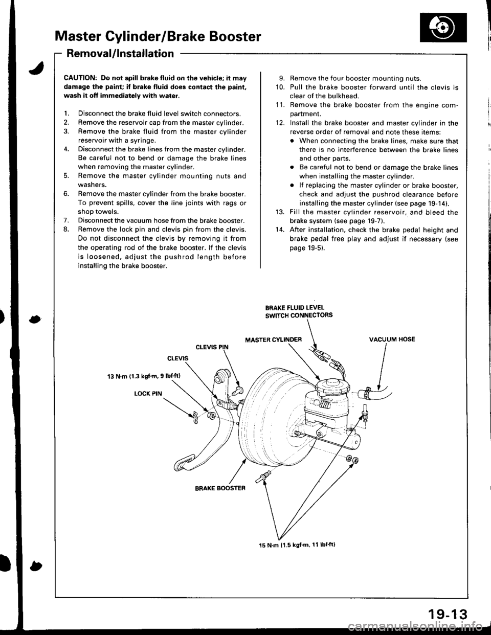
Master Cylinder/Brake Booster
I'RemovaUlnstallation
CAUTION: Do not spill brake tluid on the vehicle; it may
damage the paint; if brake fluid does contact the paint,
wash it oft immediatoly with water.
l. Disconnect the brake fluid level switch connectors.
2. Remove the reservoir cap from the master cylinder.
3. Remove the brake fluid from the master cvlinder
reservoir with a syringe.
4. Disconnect the brake lines from the master cylinder.
Be careful not to bend or damage the brake lines
when removing the master cylinder.
5. Remove the master cylinder mounting nuts and
washers.
6. Remove the master cylinder from the brake booster.
To prevent spills, cover the line joints with rags or
shoD towels.
7. Disconnect the vacuum hose from the brake booster.
8. Remove the lock pin and clevis pin from the clevis.
Do not disconnect the clevis by removing it from
the operating rod of the brake booster. lf the clevis
is loosened, adjust the pushrod length before
installing the brake booster.
13 N.m (1.3 kgf'm, 9 lbl'ft)
LOCX PIN
9. Remove the four booster mounting nuts.
10. Pull the brake booster forward until the clevis is
clear of the bulkhead.
11. Remove the brake booster from the enqine com-
panmenL
12, Install the brake booster and master cylinder in the
reverse order of removal and note these items:
. When connecting the brake lines, make sure that
there is no interference between the brake lines
and other parts.
. Be careful not to bend or damage the brake lines
when installing the master cylinder.
. lf replacing the master cylinder or brake booster,
check and adiust the DUshrod clearance before
installing the master cylinder (see page 19-14).
13. Fill the master cylinder reservoir, and bleed the
brake system (see page 19-7).'14. After installation, check the brake pedal height and
brake pedal free play and adjust if necessary (see
page 19-5).
BRAKE FLUID LEVEL
SW]TCH CONNECTORS
MASTER CYLINOERVACUUM HOSE
J
15 N.m t1.5 kgl'm, 11 lbf'ft)
Page 766 of 1681
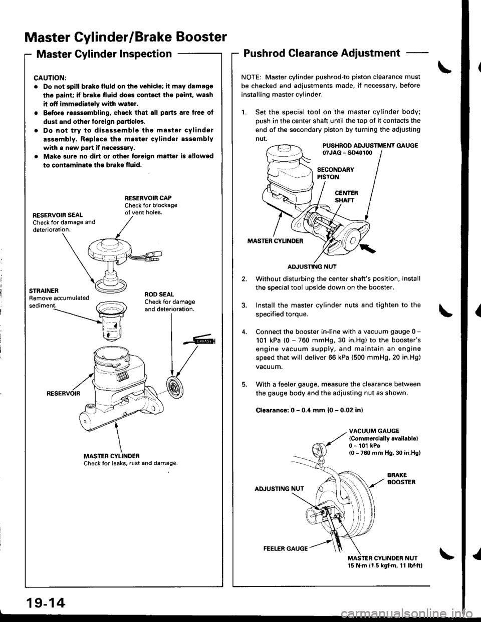
Master Cylinder/Brake Booster
Master Cylinder InspectionPushrod Clearance Adjustment
NOTE: Master cylinder pushrod'to piston clearance must
be checked and adjustments made, if necessary, before
installing master cylinder.
1. Set the special tool on the master cylinder body;
push in the center shaft until the top of it contacts the
end of the socondary piston by turning the adjusting
nut.PUS'IROD ADJUSTTTiENT GAUGE07JAG - SDiOl(xl
SECOITDARYPISTON
CEl{IERSHAFT
MASTER CYLINDER
Without disturbing the center shaft's position,
the soecial tool upside down on the booster.
3. Install the master cylinder nuts and tighten to the
sDecified toroue.
4. Connect the booster inline with a vacuum gauge 0 -
101 kPa {0 - 760 mmHg, 30 in.Hg) to the booster's
engine vacuum supply, and maintain an engine
speed that will deliver 66 kPa (500 mmHg, 20 in.Hg)
vacuum.
5. With a feeler gauge, measure the clearance between
the gauge body and the adjusting nut as shown.
Clsarance: 0 - 0,i[ mm (0 - 0.02 inl
VACUUM GAUGElCommelcially availabl€|0 - 101 kPal0 - 760 mm H9,30 in.Hgl
AINUSTING NUT
BRAKEBOOSTEB
MAS'ER CYLINDER NUT15 N.m ll.5 kgf.m. 11 lbl.ftl
CAUTION:
. Do not spill blake fluid on the vohicle; it may damago
th6 paint; if brake fluid does contast ths paint, wash
it off immsdiately with water.
. Before reassembling. chock that all parts are tree of
dust and othor toreign particlgs,
. Do not trv to dissssemblo the master cylinder
assembly. Replace the mast€r cylinder assembly
with s new part if nocossary.
. Make sure no dirt or othor toroign matter is allowed
to contaminate th€ brako fluid.
RESERVOIR SEALCheck for damage and
deterioration.
ROD SEALCheck for damageand deterioration.
AIIUSNNG NUT
19-14
FEELER GAUGE
Page 767 of 1681
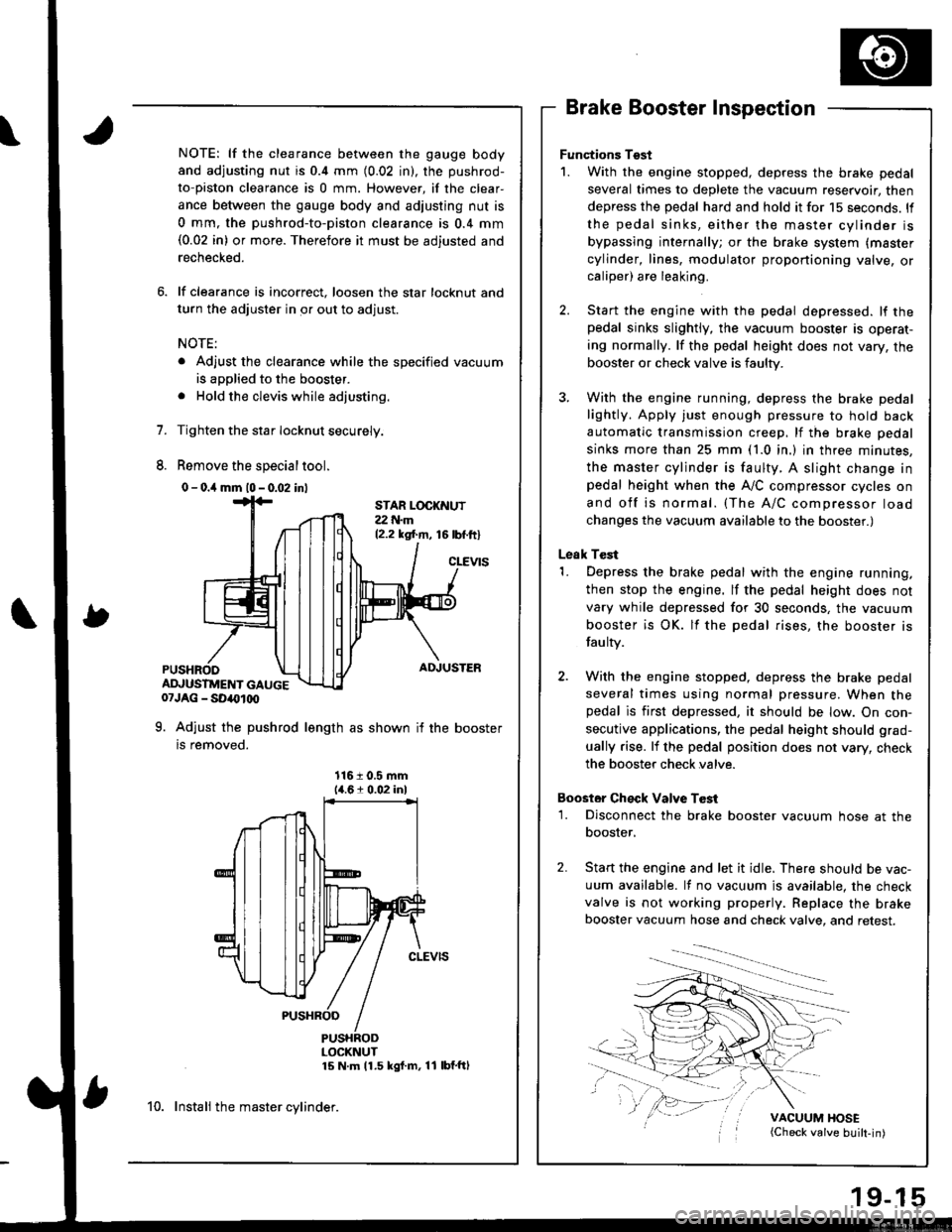
1.
8.
NOTE: lf the clearance between the gauge body
and adjusting nut is 0.4 mm (0.02 in), the pushrod-
to-piston clearance is 0 mm. However, if the clear-
ance between the gauge body and adjusting nut is
0 mm, the pushrod-to-piston clearance is 0.4 mm(0.02 in) or more. Therefore it must be adjusted and
rechecked.
lf clearance is incorrect, loosen the star locknut and
turn the adjuster in or out to adjust.
NOTE:
. Adjust the clearance while the specified vacuum
is applied to the booster.
. Hold the clevis while adjusting.
Tighten the star Iocknut securely.
Remove the special tool.
0 - o.il mm l0 - 0.02 inl
Brake Booster Inspection
Functions Tgst
1. With the engine stopped, depress the brake pedal
several times to deplete the vacuum reservoir, then
depress the pedal hard and hold it for 15 seconds. ll
the pedal sinks, either the master cylinder is
bypassing internally; or the brake system (master
cylinder, lines, modulator proportioning valve, orcaliper) are leaking.
Start the engine with the pedal depressed. lf thepedal sinks slightly, the vacuum booster is operat-
ing normally. lf the pedal height does not vary, the
booster or check valve is faulty.
With the engine running, depress the brake pedal
lightly. Apply just enough pressure to hold back
automatic transmission creep, lf the brake pedal
sinks more than 25 mm (1.0 in.) in three minutes,
the master cylinder is faulty. A slight change inpedal height when the A,,/C compressor cycles on
and off is normal. (The A/C compressor load
changes the vacuum available to the booster.)
Leak Test
1. Depress the brake pedal with the engine running,
then stop the engine. lf the pedal height does not
vary while depressed for 30 seconds, the vacuum
booster is OK. lf the pedal rises, the booster is
fau lty.
2. With the engine stopped, depress the brake pedal
several times using normal pressure. When thepedal is first depressed, it should be low. On con-
secutive applications, the pedal height should grad-
ually rise. lf the pedal position does not vary, check
the booster check valve.
Boostor Ch€ck Valve T6st
1. Disconnect the brake booster vacuum hose at the
booster,
Start the engine and let it idle. There should be vac-
uum available. It no vacuum is available. the check
valve is not working properly. Replace the brake
booster vacuum hose and check valve, and retest.
VACUUM HOSE(Check valve built-in)
STAR LOCKNUT22 t{.m12.2 ksl.m, 16lbf.ftl
cLEVtS
ADJUSTER
ADJUSTMENT GAUGE07JAG - SD40t00
9. Adjust the pushrod length as shown if the booster
is removed.
1161 0.5 mm14.61 0.02 inl
PUSHRODLOCKNUT15 N m 11.5 kgf m, 11 lbf'ftl
10. Instali the master cylinder.
Page 768 of 1681
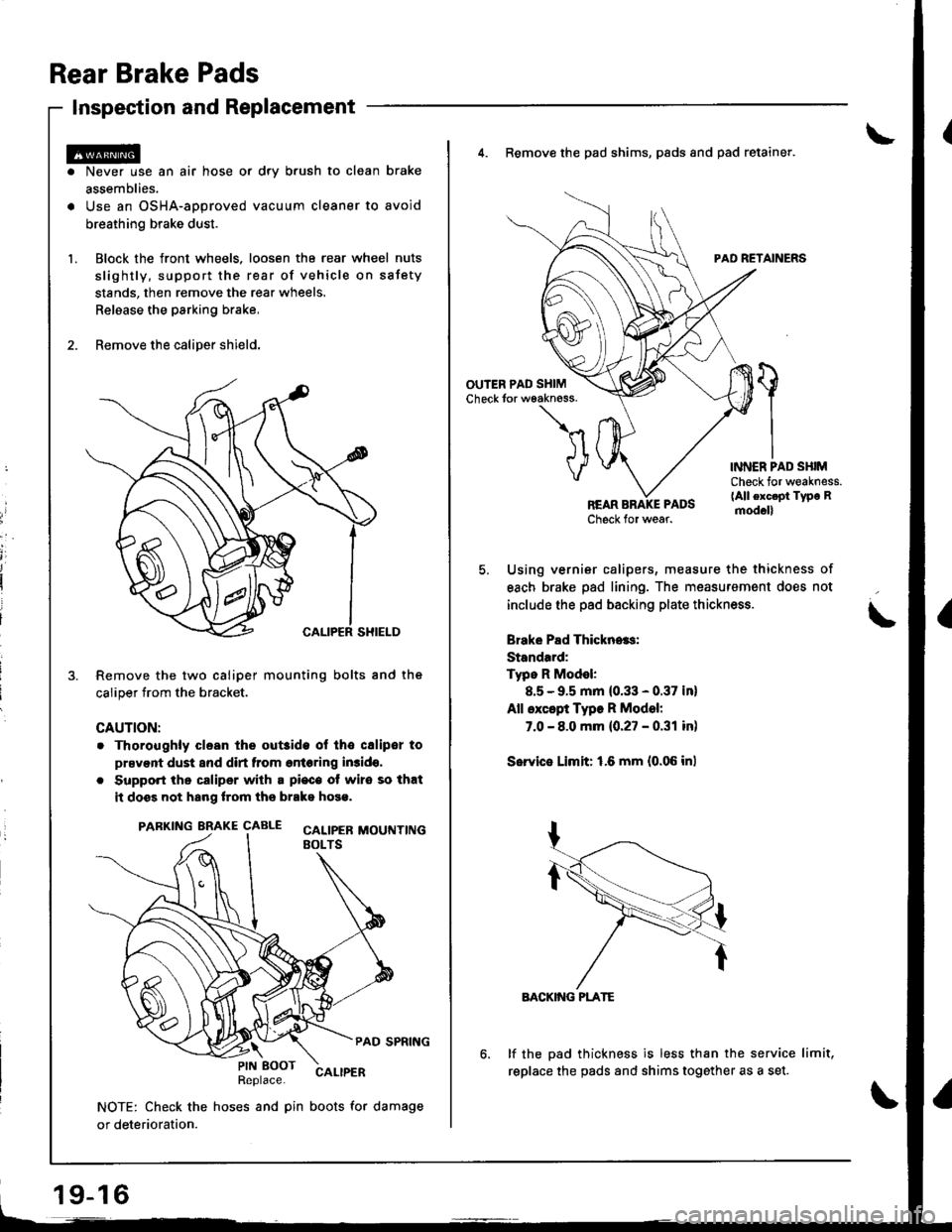
Rear Brake Pads
Inspection and Replacement
Never use an air hose or dry b.ush to clean brake
assemblies.
Use an OSHA-approved vacuum cleaner to avoid
breathing brake dust.
Block the front wheels. loosen tha rear wheel nuts
slightly, support the rear of vehicle on sstety
stands, then remove the rear wheels.
Relaase the parking brake,
Remove the caliper shield.
Remove the two caliper mounting bolts and the
caliper trom the bracket.
CAUTION:
. Thoroughly clesn the out3ide ol tho csliper to
prsvent dust and dirt from entering in3ido,
. Support the caliper with a pi€c€ ot wire so that
it doss not hang lrom ths brako hose.
PARKING BRAKE CAALE cALtpEB MOUTTT|NGEOLTS
PAD SPRING
Replace.CALIPER
NOTE: Check the hoses and pin boots for damage
or deterioration.
\PIN EOOT
19-16
4. Remove the pad shims, pads and pad retainer.
PAD RETAINERS
'l
VINNER PAD SHIMCheck for weakness.(All exc.pt Type Rmod.ll
Using vernier calipers, measure the thickness of
each brake pad lining. The measurement does not
include the pad backing plate thickness.
Brake Pad Thickn..s:
Standard:
Typo R Model:
8.5 - 9.5 mm (0.33 - 0.37 in)
All except Type R Model:
7.0 - 8.0 mm {0.27 - 0.31 in)
Sorvie Limit: 1.6 mm {0.06 inl
BACKIiIG PLATE
lf the pad thickness is less than the service limit,
replace the pads and shims together as a set.
Page 769 of 1681
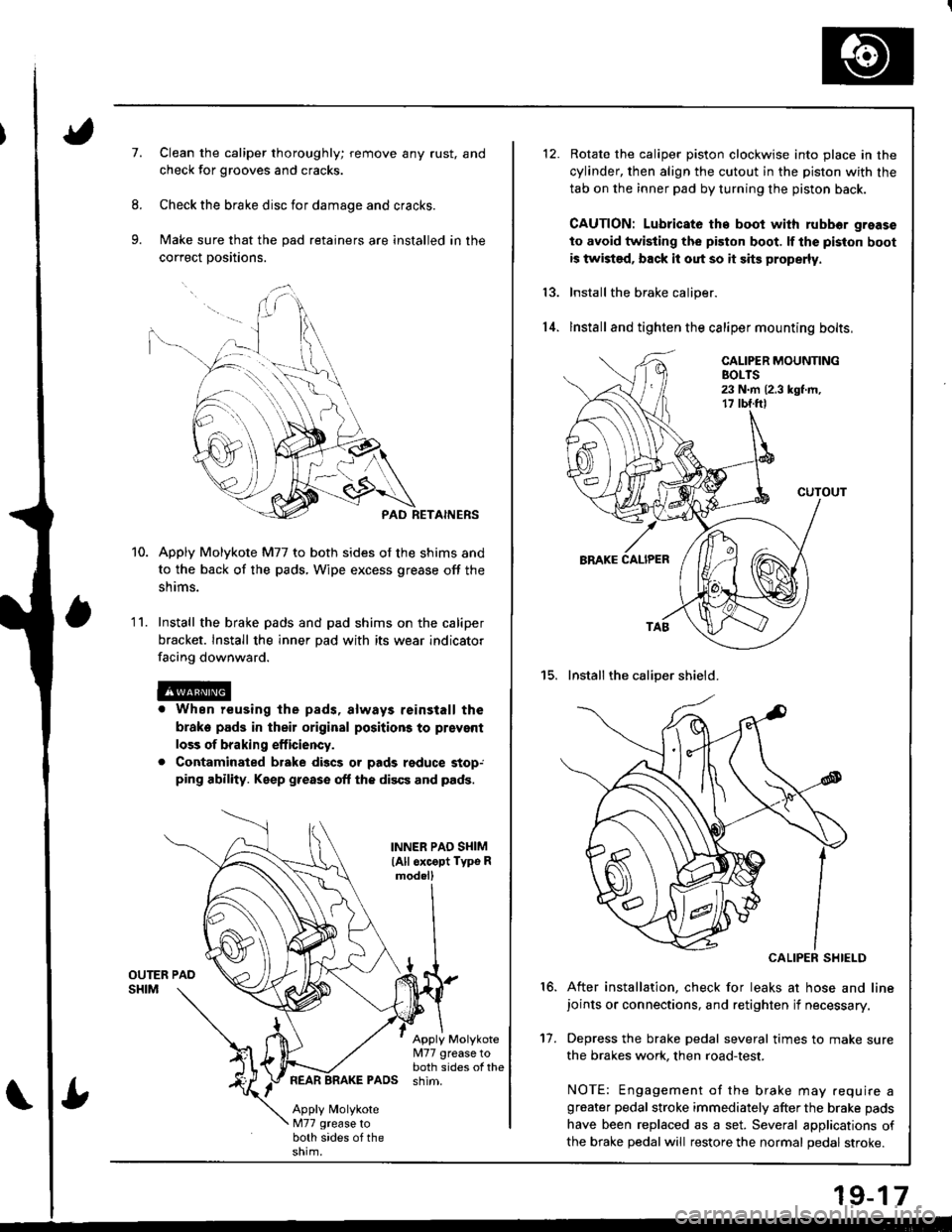
7.Clean the caliper thoroughly; remove any rust, and
check for grooves and cracks.
Check the brake disc for damage and cracks.
Make sure that the pad retainers are installed in the
correct positions.
PAD RETAINERS
Apply Molykote M77 to both sides of the shims and
to the back of the pads, Wipe excess grease off the
snrms.
Install the brake pads and pad shims on the caliper
bracket. Install the inner pad with its wear indicator
facing downward.
r When reusing the pads, always reinstall the
brake pads in their original positions to prsvent
loss of braking efficiency.
. Contaminated brake discs or pads reduce stop,ping ability. Keep grease off the discs and pads.
1 '�I.
INNER PAO SI{IM
lAll oxcopt Typo Rmod.ll
Apply Molykote[I77 grease toboth sides of thePADS shim.
Apply MolykoteM77 grease toboth sides of the
Rotate the caliper piston clockwise into place in the
cylinder, then align the cutout in the piston with the
tab on the inner pad by turning the piston back.
CAUTION: Lubricato th€ boot with rubbor grease
to avoid twisting the piston boot. lf the piston boot
is twist€d, back it out so it sits properly.
Install the brake caliper.
lnstall and tighten the caliper mounting bolts,
15. Installthe caliper shield.
CALIPER SHIELD
After installation, check for leaks at hose and linejoints or connections, and retighten if necessary.
Depress the brake pedal several times to make sure
the brakes work, then road-test.
NOTE: Engagement of the brake may .equire agreater pedal stroke immediately after the brake pads
have been replaced as a set. Several applications of
the brake pedal will restore the normal pedal stroke.
13.
14.
16.
't7.
19-17
Page 770 of 1681
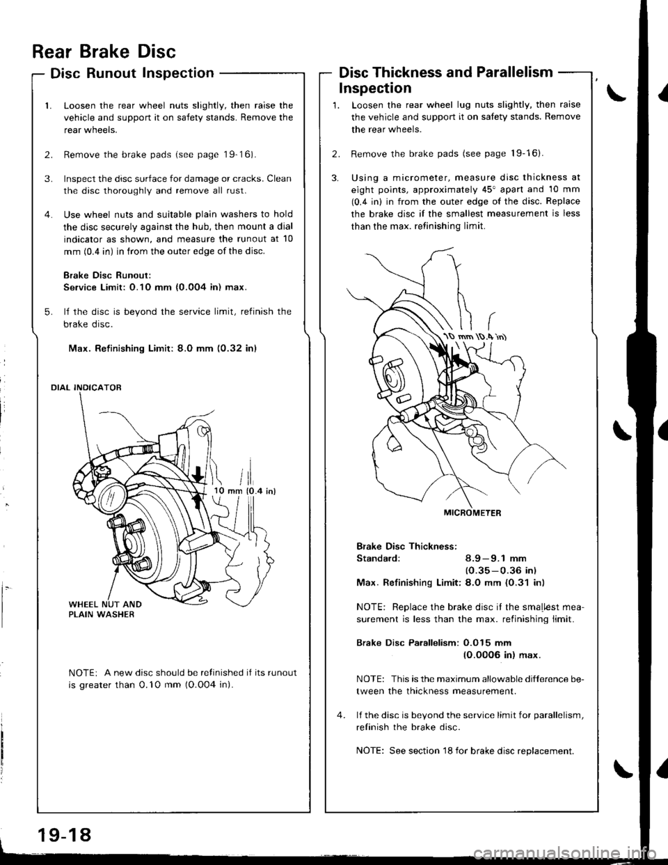
Inspection
rrii tlmm {0.4 inl10
l.
Rear Brake Disc
Disc Runout Inspection
Loosen the rear wheel nuts slightly, then raise the
vehicle and support it on safety stands. Remove the
rear wneers.
Remove the brake pads (see page 19-16).
Inspect the disc surface for damage or cracks. Clean
the disc thoroughly and remove all rust.
Use wheel nuts and suitable plain washers to hold
the disc securely against the hub, then mount a dial
indicator as shown, and measure the runout at 10
mm (0.4 in) in from the outer edge of the disc.
Brake Disc Runout:
Se.vice Limit: O.1O mm {0.0O4 in) max.
ll the disc is beyond the service limit, refinish the
brake disc.
Max. Refinishing Limit: 8.0 mm (0.32 in)
DIAL INDICATOR
NOTEi A new disc should be refinished if its runout
is greater than 0.'10 mm (O.O04 in).
Disc Thickness and Parallelism
Loosen the rear wheel lug nuts slightly, then raise
the vehicle and support it on safety stands. Remove
the rear wheels.
Remove the brake pads (see page 19-16).
Using a micrometer, measure disc thickness at
eight points, approximately 45" apart and 10 mm
(0.4 in) in from the outer edge of the disc. Replace
the brake disc if the smallest measurement is less
than the max. retinishing limit.
Bfake Disc Thickness:
Standard: 8.9 - 9.1 mm
(0.35-0.36 in)
Max. Refinishinq Limit:8.O mm (0.31 in)
NOTE: Replace the brake disc it the smaLlest mea-
surement is less than the max. retinishing limit.
Brake Disc Parallelism: O.O15 mm
(O.00O6 in) max.
NOTE: This is the maximum allowable difference be-
tween the thickness measurement.
lf the disc is bevond the service limit for parallelism,
refinish the brake disc.
NOTE: See section 18 for brake disc replacement.
\S rnrn .\'rn)
19-18