HONDA INTEGRA 1998 4.G Workshop Manual
Manufacturer: HONDA, Model Year: 1998, Model line: INTEGRA, Model: HONDA INTEGRA 1998 4.GPages: 1681, PDF Size: 54.22 MB
Page 811 of 1681
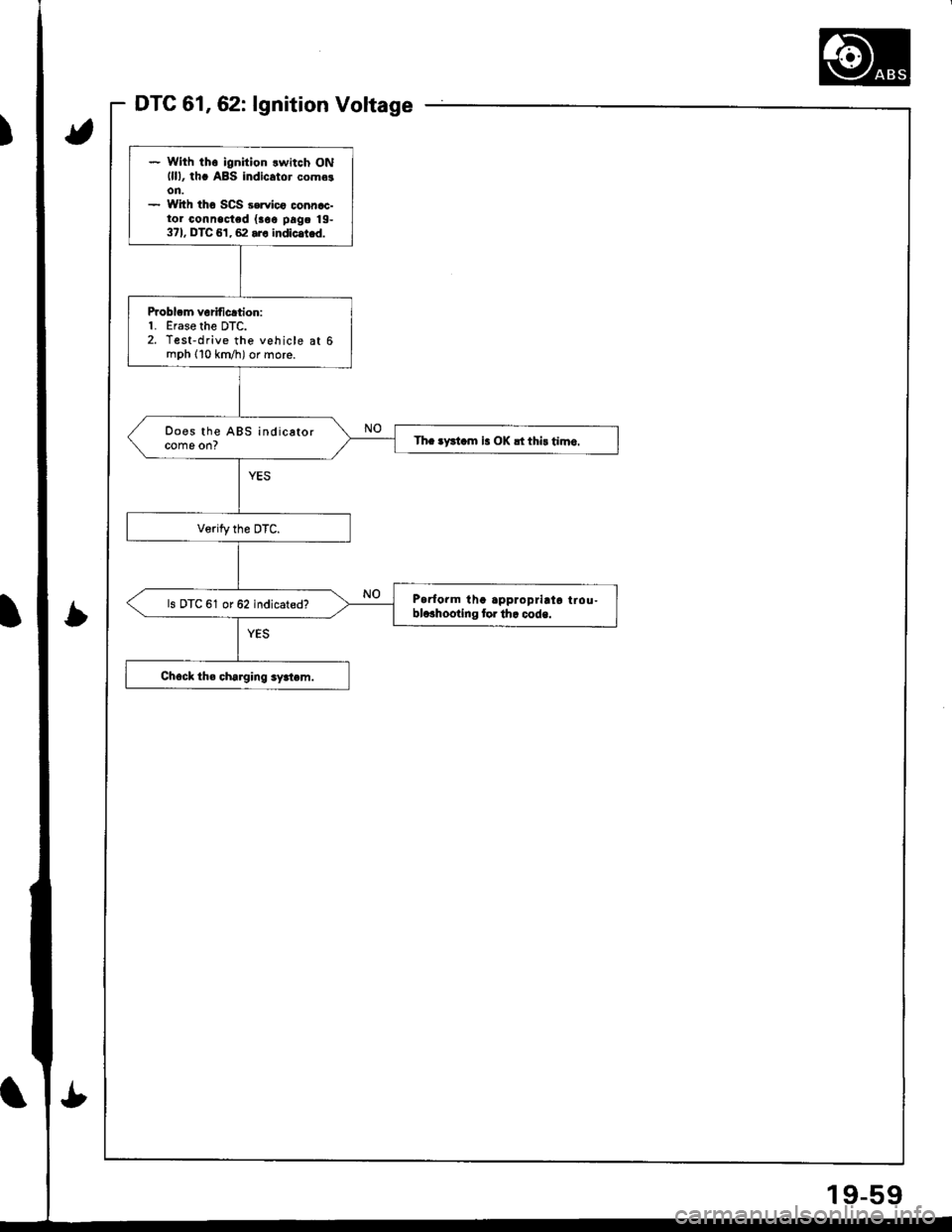
DTC 61,62: lgnition Voltage
* With th6 ignition lwitch ONlll), th. ABS indicator come!on.- With tho SCS 3ervico connac-tor connected {aoe pag. 19-371, DTC 61, 62 .r. indlc.t d.
Problcm veriticrtion:1. Erase the DTC.2. Test-drive the vehicle at 6mph (10 km/h) or more.
Does the ABS indicatorcome on?Th. tFl.m is OK !t thi! timo.
Parform tha approprirta lrou-blcahooting tor th. code.ls DTC 61 or 62 indicated?
!t
19-59
Page 812 of 1681
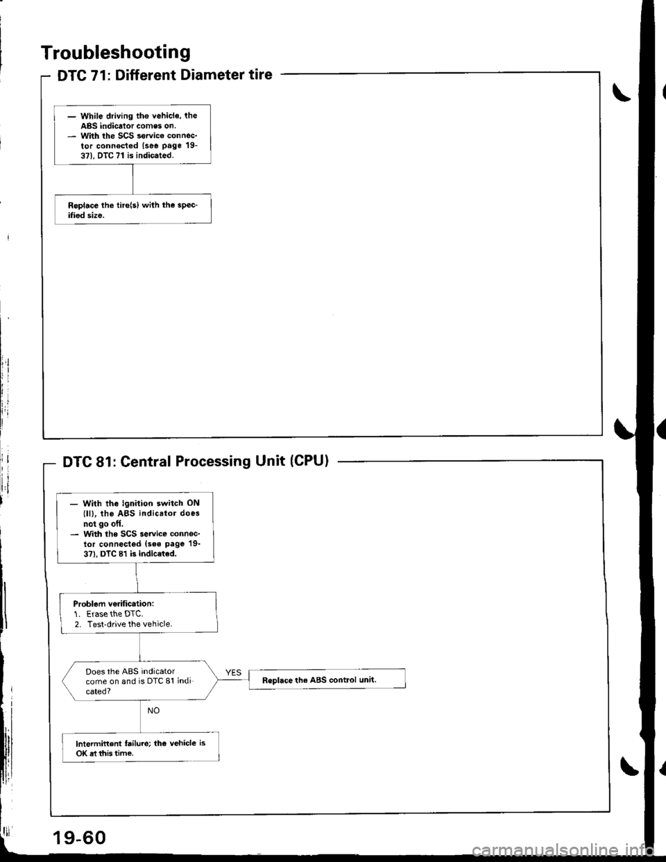
DTC 71: Different Diameter tire
- While driving the vehicl€. theABS indicator comes on.- With the SCS sorvico connec-tor connocted (see page 19-371. DTC 71 is indicated.
Troubleshooting
Central Processing Unit (CPU)
- With the ignition switch ON(lll, tho ABS indicator does
not go off.- With the SCS service connec-lor connectgd (sss page 19-
3?), DTC 81 is indic€ted.
Problem ve.ification:1. Erase the DTC.2. Test-drive the vehicle.
Does the ABS indicatorcome on and is DTC 81 indicated?
R€place th6 ABS control unit.
lntermittent failure; the vehicle is
OK rt this time.
19-60
Page 813 of 1681
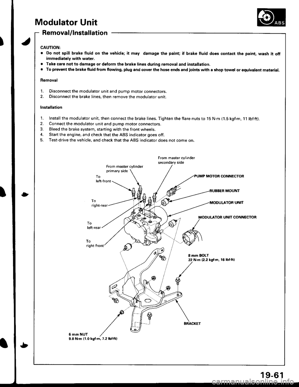
Modulator Unit
Removal/lnstallation
CAUTION:
. Do not spill brake fluid on lhe vehicle; it may damage the paint; il brake fluid does contact the paint, wash it offimmediately with water.
. Tak€ care notto damage or delorm the brake lines during removal and installation.. To provont the brake fluid ftom flowing, plug and cover the hos€ ends and ioints with a shop towel or equiyalent material.
Removal
1. Disconnect the modulator unit and DUmD motor connectors.
2. Disconnect the brake lines, then remove the modulator unit.
Installation
1. lnstall the modulator unit, then connect the brake lines. Tighten the flare nuts to 15 N.m (1.5 kgf.m, 11 lbf.ft).2. Connect the modulator unit and pump motor connectors.
3. Bleed the brake system, starting with the front wheels.
4. Start the engine, and check that the ABS indicator goes off.
5. Test-drive the vehicle, and check that the ABS indicator does not come on.
From master cylinder
from master cylinderprimary side
PUMP MOTOB CONNECTOR
MOUNT
UNlT
MODULATOR UNIT CONNECTOR
toright front
8 mm EOLT22 N.m {2.2 kg[.m, 16 lbl.ftl
6 mm NUT9.8 N.m 11.0 ks{.m,7.2lbtftl
9-6
Page 814 of 1681
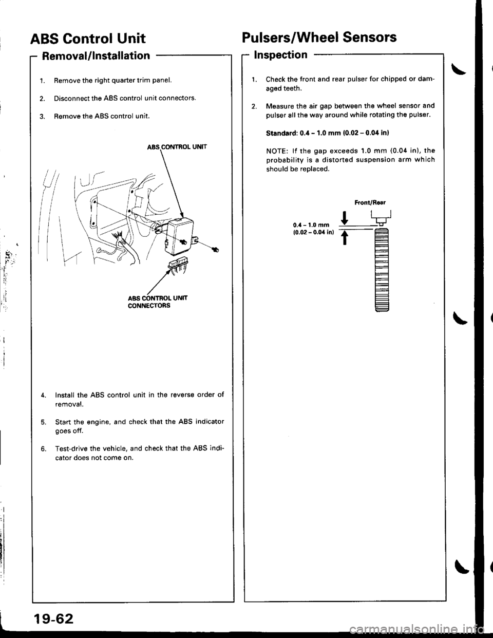
ABS Control Unit
RemovaUlnstallation
1. Remove the right quarter trim panel.
2. Disconnect the ABS control unit connectors.
3. Remove the ABS control unit.
Pulsers/Wheel Sensors
Inspection
/t
l\
I
Check the front and rear pulser for chipped or dam-
aged teeth.
Measure the air gap between tho wheel sensor and
pulser sllthe way around while rotating the pulser.
Standard: 0.4 - 1.0 mm (0.02 - 0.04 in)
NOTE: lf the gap exceeds 1.0 mm (0.04 in), the
probability is a distorted suspension arm which
should be reDlaced.
Front/R..1
L-TJ
.t-
t=
l-
Et-E_
Install the ABS control unit in the reverse order of
removal.
Start the engine, and check that the ABS indicator
goes off.
Test-drive the vehicle, and check that the ABS indi-
cator does not come on.
19-62
Page 815 of 1681
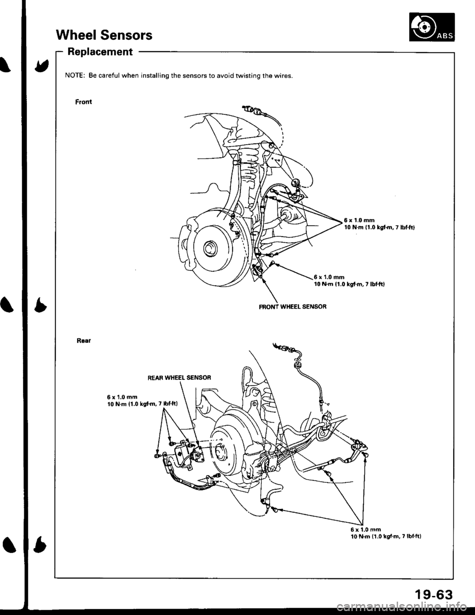
Wheel Sensors
Replacement
t5
Ib
NOTE; Be careful when installing the sensors to avoid twisting the wires
Front
6x1.0mm10 N.m {1.0 kglm,7 lbf.ft}
6 x '1.0 mml0 N.m 11,0 kgt.m,7 lbl.ftl
Rlal
6x1.0mm10 N.m 11.0 ksf.m,7 lbf ft)
6x1.0mm10 N.m (1.0 kgl.m, 7 lbfft)
FNONT WHEEL SENSOR
9-63
Page 816 of 1681
!
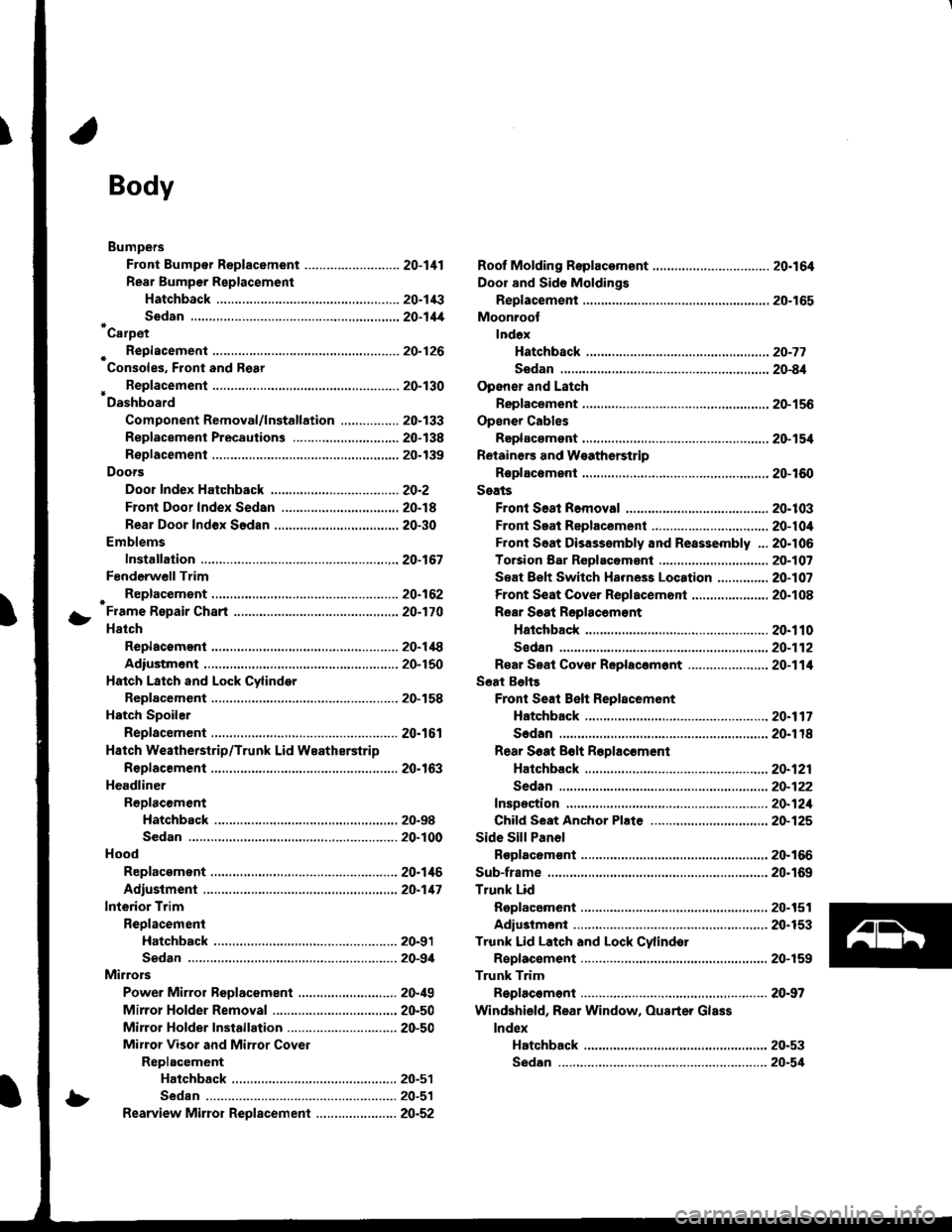
Body
Bumpers
Front Bumper Replacement ....................-..... 20-111
Rear Bumpar Replacemeni
Hatchback ................. 20-1/B
Sedan .................... ....20-111'Carpet
. Repfacemenl .,.,.,.,,..-....-.20-126
Consoles, Front and Rear
* Replacement ..................20-130
Dashboard
Component Removal/lnstallation ................ 20-133
Replacement Precautions ...........,................. 20-138
R€placement ....,.,...........20-139
Doors
Door Index Hatchback ................................... 20-2
Front Door Index Sedan .................,.,..,.,....,.. 20-18
Rear Door Index Sedan ........,.,........,.............. 20-30
Emblems
Installation .....................20-167
FenderwellTrim
+ Replacement., ................20.162
Fram€ Repair Chart .-..........20-170
Hatch
Replacoment .......,..........20-118
Adiustment .................... 20-150
Hatch Latch and Lock Cylinder
Replacement ..,.,..... ........ 20-158
Hstch Spoiler
Replacement ......... .......-.20.161
Hatch Weatherstrip/Trunk Lid Wsatherstrip
Replacement ..................20.163
Headliner
ReDlacement
Hatchbsck ,.,....,......,.. 20-98
Sedan .........................................................20-100
Hood
Replacsment ......... ......... 20.146
Adiustment ....................20-117
lnterior Trim
Reolacement
Hatchback ................. 20-91
Sedan .........................................................20-9,1
Mirrors
Power Mirror Reolacement ..........,................ 20-49
Mirrol Holder Removal ............................,..... 20.50
Mirror Holder Installation .............................. 20-50
Mirror Visor and Mirrot Covet
Replacement
Haichback ............20-51
Sedan .................................................... 20-51
Rearview Mirror Reolacement ..........-....-.-.... 20.52
Roof Molding Rep|acament ................................ 20.164
Door and Sid€ Moldings
Replacement .,..........,..... 20-165
Moonroot
lnd6x
Hatchback -................20-77
Sodan .........................................................20-8il
Opener and Latch
Replacement .......... ......,. 20-156
Opensr Cables
Replacamsnt .,.,...,.. ......., 20-154
Retainers and W€atherstrip
Replacement .................. 20-160
Seats
Front Seat Romoval ....................................... 20-103
Front Seat Replacement ...........................,.,.. 20-104
Front Soat Disassembly and Reassembly ...20-106
Torsion Bar ReDlacomant .....,...,......,.......,..,., 2O-1O7
Seat Eelt Switch Ha.ness Location ..,...,.,.,..,2O-1O7
Front Seat Cover Replacemont ..,....,..,..,.....,. 20-108
Rear Soat Roplscemont
Hatchback ................. 20.110
Sedan.........................................................20-112
R€al Seat Cover Replacomont ...................... 20-114
Seat Belts
Front Seat Beh Replacement
Hatchback..................20.117
Sedan20-r18
Rear S6at Bolt R€plac€ment
Hatchback .-......-.-......20-121
Sedan.......................-.-....-.-..........-.............20-122
fnspection ......-.-.,....-.-....20-121
Chifd Seat Anchor Plate ................................ 20-125
Side Sill Panol
Beplacom€nt .................. 20-166
Sub-frame ........................... 20.169
Trunk Lid
Replacement ......... ..,..,.,.20-151
Adiustmeni .................... 20-153
Trunk Lid Latch and Lock Cvlindot
Replac€ment ......... ......... 20-159
Trunk Trim
Replacement .,.,,.,........... 20-97
Windshield, Rear Window, Ouarter Glass
lndex
Hatchback ...........,,.20-53
!
S6dan ......................................................... 20.54
Page 817 of 1681
Doors
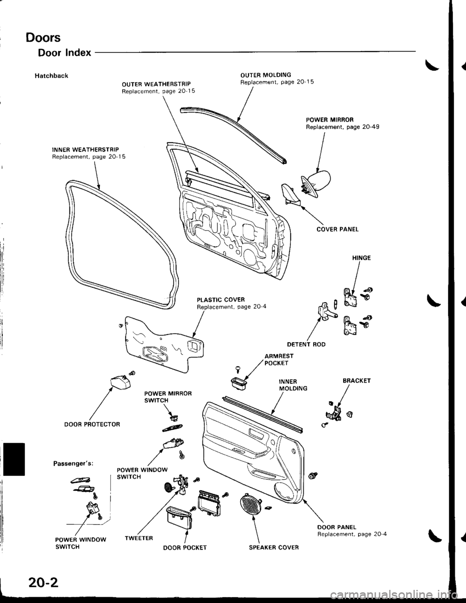
Door lndex
HatchbackOUTER MOLDINGReplacement, Page 20 15OUTER WEATHERSTRIPReplacement, page 20-1 5
INNER WEATHERSTRIPReplacement, page 20-1 5
POWER MIRRORReplacement, page 2o-49
COVER PANEL
PLASTIC COVERReplacement, Page 20 4
HINGE
I
ffis
,ad
mr
,tA g
lF
T ROD
DOOR PANELReplacement, page 20 4
i'-t"-
lGN=*sS)
20-2
SPEAKER COVER
Page 818 of 1681
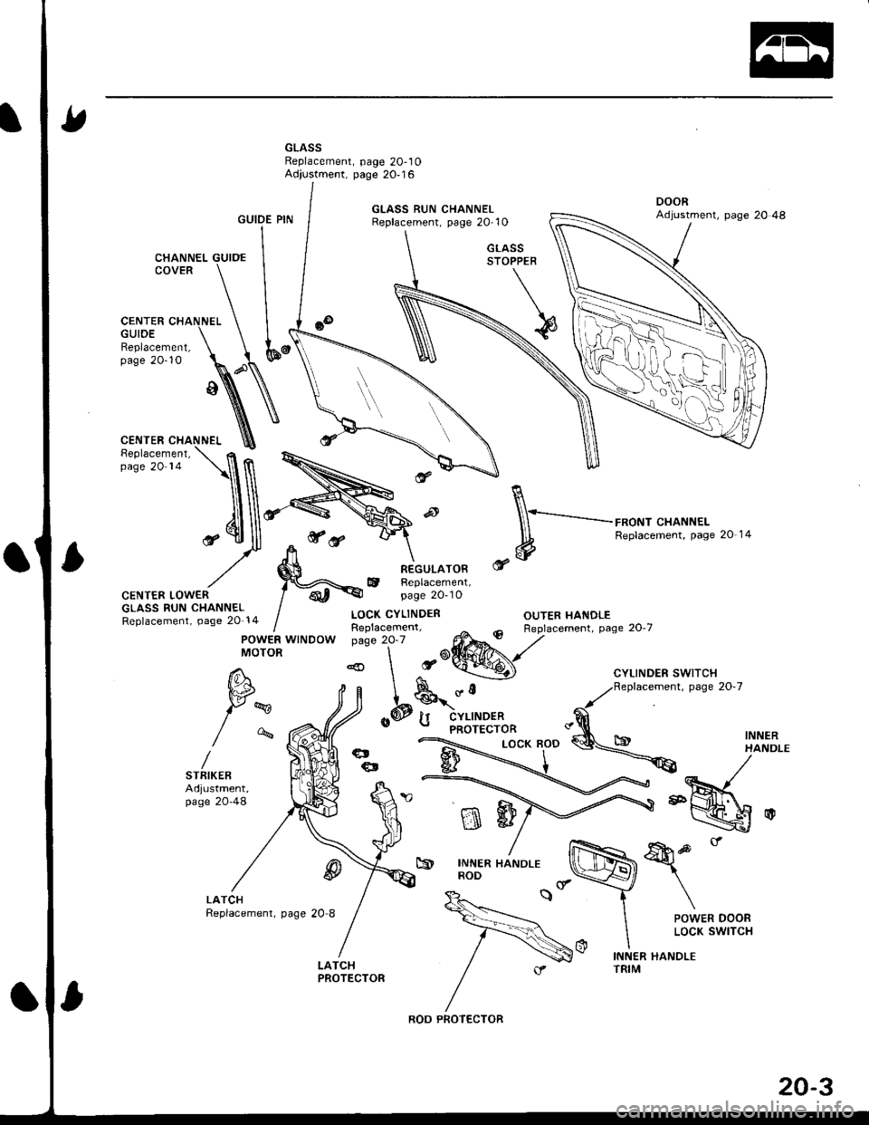
GLASSReplacement, page 20,10Adjustment, page 20-16
GUIDE PIN
CENTER CHANNELGUIDE
,**ry
R
\-_-..........-..-.-,*oNr .HANNEL
* #
Replacemenr. pase 20 14
OUTER HANDLE
mw
&p.'
\
POWER DOORLOCK SWITCH
c9INNER HANDLEROD
INNER HANDLETRIM
Replacement,page 20-10
CENTER LOWERGLASS RUN CHANNELReplacement, page 20-14
@
LOCK CYLINDER
REGULATORReplacement,page 2O-10
POWER WINDOWMOTOR
W
/-%
STFIKERAdjustment,page 20-48
@
ROD PROTECTOR
20-3
Page 819 of 1681
Doors
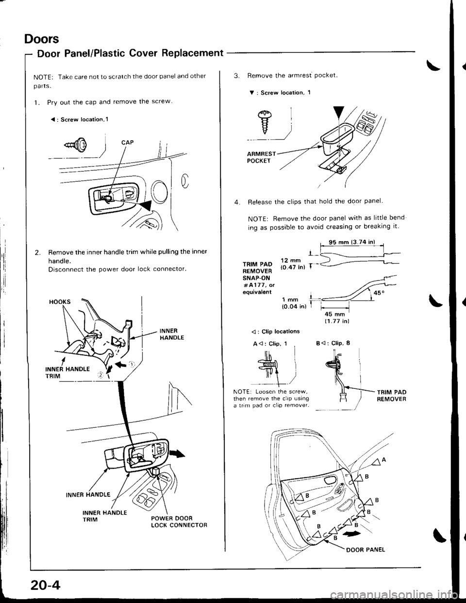
Door Panel/Plastic Cover Replacement
NOTE: Take care not to scratch the door panel and other
parts.
1. Pry out the cap and remove the screw
<: Screw location,l
Remove the inner handle trim while pulling the inner
handle.
Disconnect the power door lock connector.
'l
I
i
20-4
3.Remove the armrest Pocket.
v : Screw location, I
/eF\
YIv//
ARMRESTPOCKET
4. Release the clips that hold the door panel.
NOTE: Remove the door panel with as little bend
ing as possible to avoid creasing or breaking it'
95 mm {3.74 inl
nYLf*P to.ci int r-
-L<------=-r-
132\. .-2=---REMOVERSNAP-ON#4177, orequivalent
11.77 in)
<: Clip locations
TRIM PADREMOVERthen remove the clip usinga trim pad or clip remover-
Page 820 of 1681
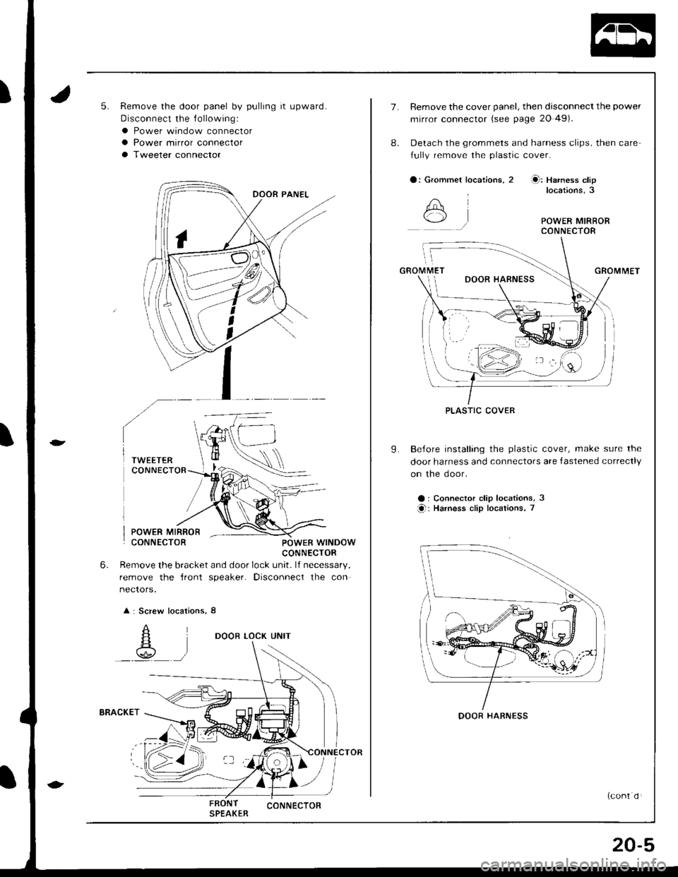
5.Remove the door panel by pulling it upward.
Disconnect the f ollowing:
a Power window connectora Power mirror connector
a Tweeter connector
POWER MIRRORCONNECTORPOWEB WINDOWCONNECTOR
Remove the bracket and door lock unit. lf necessary,
remove the {ront speaker. Disconnect the con
nectors.
: Screw locations, 8
DOOR LOCK UNIT
FRONT CONNECTORSPEAKER
6.
PLASTIC COVER
7.Remove the cover panel, then disconnect the power
mirror connector (see page 20 49)
Detach the grommets and harness clips, then care
fully remove the plastic cover.
a: Grommet locat;ons, 2 Q: Harness cliplocations,3
GROMMET
BeJore installing the plastic cover, make sure the
door harness and connectors are {astened correctly
on the door.
a : Connector clip locations, 3
O: Harness clip locations, 7
8.
A
9.
DOOR HABNESS
20-5