HONDA INTEGRA 1998 4.G Workshop Manual
Manufacturer: HONDA, Model Year: 1998, Model line: INTEGRA, Model: HONDA INTEGRA 1998 4.GPages: 1681, PDF Size: 54.22 MB
Page 901 of 1681
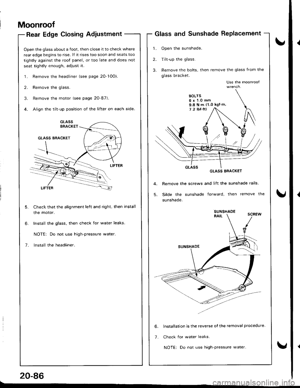
Moonroof
Rear Edge Closing Adjustment
Open the glass about a foot, then close it to check where
rear edge begins to rise. l,f it rises too soon and seats too
tightly against the root panel, or too late and does not
seat tightly enough, adjust it.
1. Remove the headliner (see page 20-1O0).
2. Remove the glass.
3. Remove the motor (see page 20'87).
4. Align the tilt-up position of the lifter on each side.
Check that the alignment left and right, then install
the motor.
Install the glass, then check for water leaks.
NOTE: Do not use high-pressure water.
lnstall the headliner.
20-86
Glass and Sunshade RePlacement
1. Open the sunshade.
2. Tilt-up the glass.
3. Remove the bolts, then remove the glass lrom the
glass bracket.
Use the moonroof
GLASS ERACKET
Remove the screws and lift the sunshade rails
Silde the sunshade forward, then remove the
sunsnaqe.
SUNSHADERAIL
lnstallation is the reverse ofthe removal procedure.
Check for water leaks.
NOTE: Do not use high-pressure water.
9.8 N m (1.0 kgl m,
6.
7.
Page 902 of 1681
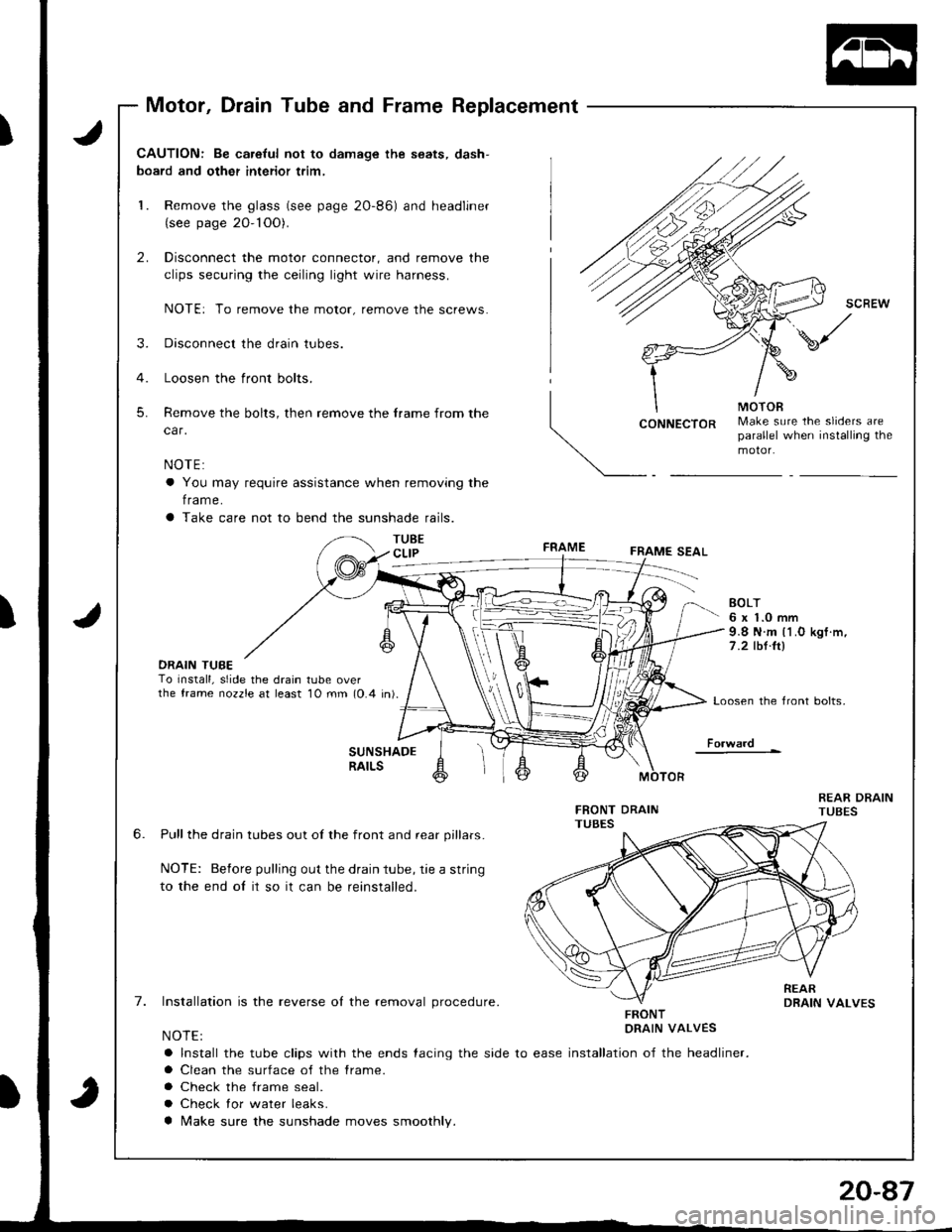
Motor, Drain Tube and Frame Replacement
J
J
CAUTION: Be ca.eful not to damage the seats, dash-
board and other interior trim,
1. Remove the glass (see page 2O-86) and headliner(see page 20- 1OO).
2. Disconnect the motor connector, and remove the
clips securing the ceiling light wire harness.
NOTE: To remove the motor, remove the screws.
3. Disconnect the drain tubes.
4. Loosen the front bolts.
5. Remove the bolts, then remove the frame from the
car.
NOTE:
a You may require assistance when removing the
f rame.
a Take care not to bend the sunshade rails.
TUBECLIP
CONNECTORMake sure the sliders areparallel when installing themotor.
FRAMEFRAME SEAL
DRAIN TUBETo Install, slide the drain tube overthe frame nozzle at least 10 mm (0.4 in).
EOLT6 x 1.0 mm9.8 N.m l1.O kgf .m,
7 .2 tbt.ltl
Loosen the front bolts,
Fo.ward
6.
7.
SUNSHADERAILS
Pull the drain tubes out of the front and rear pillars.
NOTE: Before pulling out the drain tube, rie a string
to the end oI it so it can be reinstalled.
Installation is the reverse ol the removal procedure.
NOTE:
a Install the tube clips with the ends {acing the side to ease
a Clean the surface of the frame.
a Check the frame seal.
a Check lor water leaks.
a Make sure the sunshade moves smoothly.
FRONTDRAIN VALVES
installation of the headliner.
Page 903 of 1681
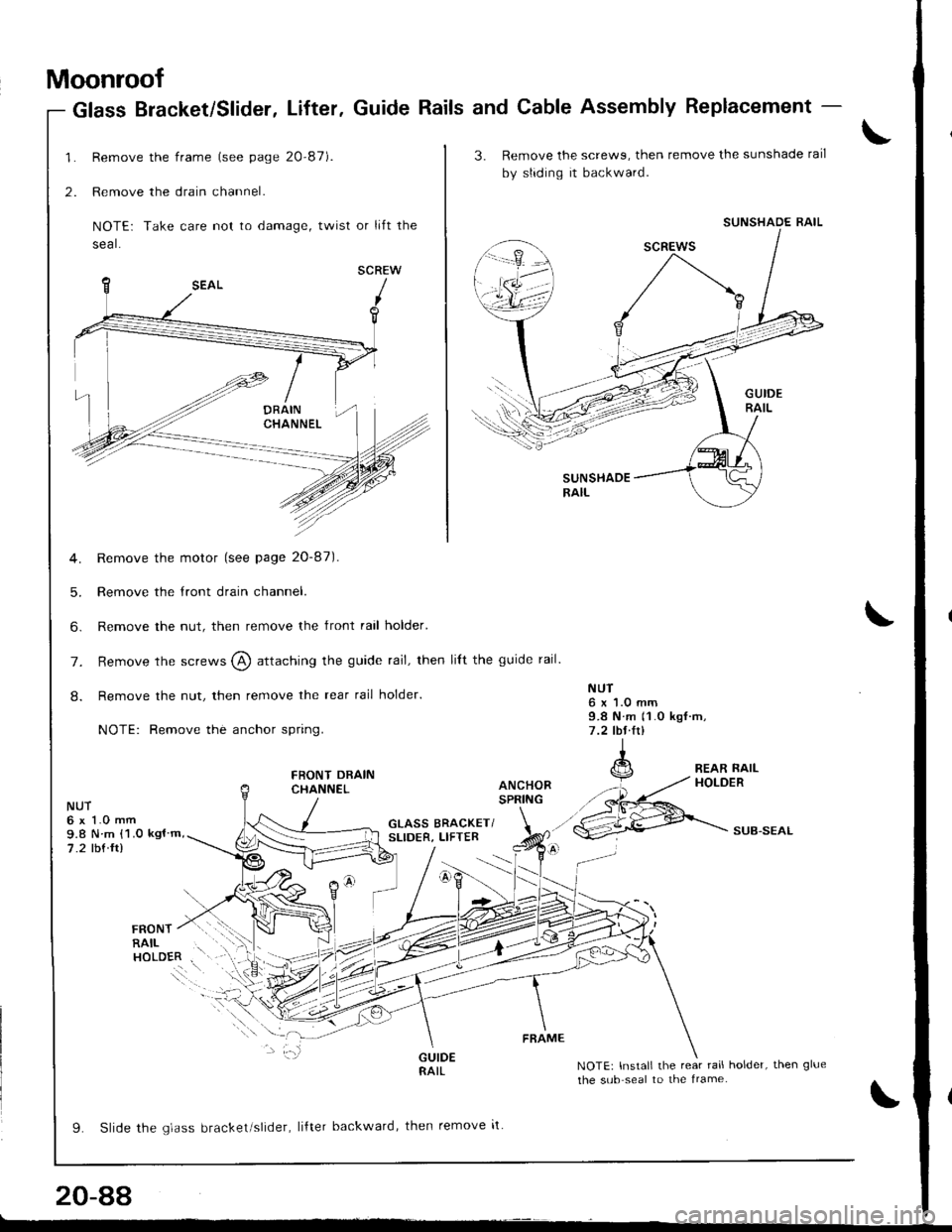
Moonroof
Remove the frame (see page 20-87).
Remove the drain channel.
NOTE: Take care not to damage, twist or lift the
seal.
SCREW
Remove the motor (see page 20-87).
Remove the tront drain channel.
Remove the nut, then remove the front rail holder'
Glass Bracket/Slider, Lifter. Guide Rails and Cable Assembly Replacement -
1.
2.
5.
6.
NUT6x1.0mm9.8 N m 11.0 kgf rrt,7 .2 lbl.lrl
GLASS BRACKET/SLIDER, LIFTERSUB.SEAL
rnorur / r.l .i:'r
RAIL . ',.;.
"o.ol.. i\
9. Slide rhe qldss brackel slrder, liftel backward, then remove it
NOTE: Install the rear rail holder, then glue
the sub seal to the lrame.
FRAME
20-88
3. Remove the screwg, then remove the sunshade rail
by sliding it backward.
SUNSHADERAIL
SUNSHADE RAIL
7. Remove the screws @ attaching the guide rail, then lilt the guide rail.
8. Remove the nut, then remove the rear rail holder.
NOTE: Remove the anchor spring.
FRONT DRAINCHANNEL
NUT6 x 1.0 mm9.8 N m {1.0 kgl m,
7.2 tbf ft)
L-
Page 904 of 1681
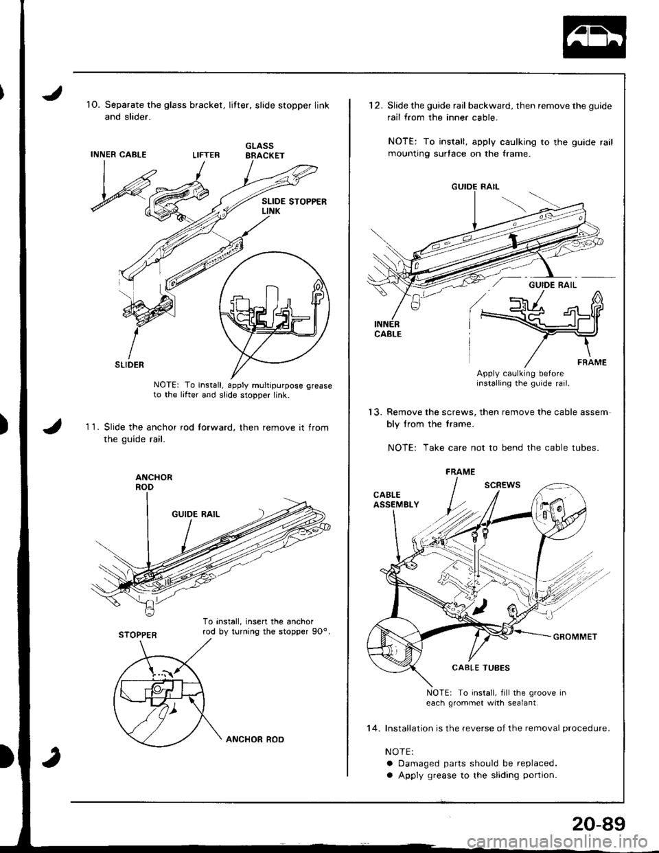
1O. Separate the glass bracket,
and slider.
INNER CABLE
litt€r, slide stopper link
GLASSBRACKET
11.
SLIDER
NOTE: To install, apply multipurpose greaseto the lifter and slide stopper link.
Slide the anchor rod forward, then remove it from
the guide rail.
STOPPER
To install, insert the anchorrod by turnjng the stopper 9Oo.
ANCHOR ROD
14.
20-89
'12.Slide the guide rail backward, then remove the guide
rail from the inner cable.
NOTE: To install, apply caulking to the guide rail
mounting surtace on the frame.
Apply caolking beforeinstalling the guide rail.
'13. Remove the screws, then remove the cable assem
bly trom the f rame.
NOTE: Take care not to bend the cable tubes.
NOTE: To install, fill the groove Ineach grommet with sealant.
Installation is the reverse of the removal procedure.
NOTE:
a Damaged parts should be replaced.
a Apply grease to the sliding portion.
FRAME
Page 905 of 1681
Moonroof
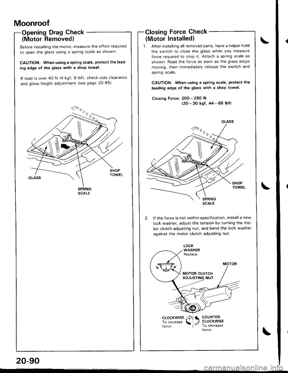
Opening Drag Check
(Motor Removedl
Before installing the motor, measure the effort required
to open the glass using a spring scale as shown.
CAUTION: When using a spring scale, protecl the lead-
ing edge ot the glass with a shop towel.
lf load is over 40 N (4 kgl, 9 lbfi, check side clearance
and glass height adjustment (see page 20-85)
Closing Force Check
{Motor Installed}
'1 . Alter installing all removed parts, have a helper hold
the switch to close the glass while you measure
Jorce required to stop it. Attach a spring scale as
shown. Read the lorce as soon as the glass stops
moving, then immediately release the switch and
spring scale.
CAUTION: when using a spring scale, protecl the
leading edge oI the glass with a shop towel.
Closing Force: 200-290 N
(20-30 ksf,44-66 lbtl
lf the force is not within specitication, install a new
lock washer, adiust the tension by turnlng the mo-
tor clutch adjusting nut, and bend the lock washer
against the motor clutch adjusting nut.
GLASS
\
clocKwrsE /?l a COUNTER-
To Increase \1, CLOCKWISE
force I lo oecreaseforce
20-90
--
Page 906 of 1681
Interior Trim
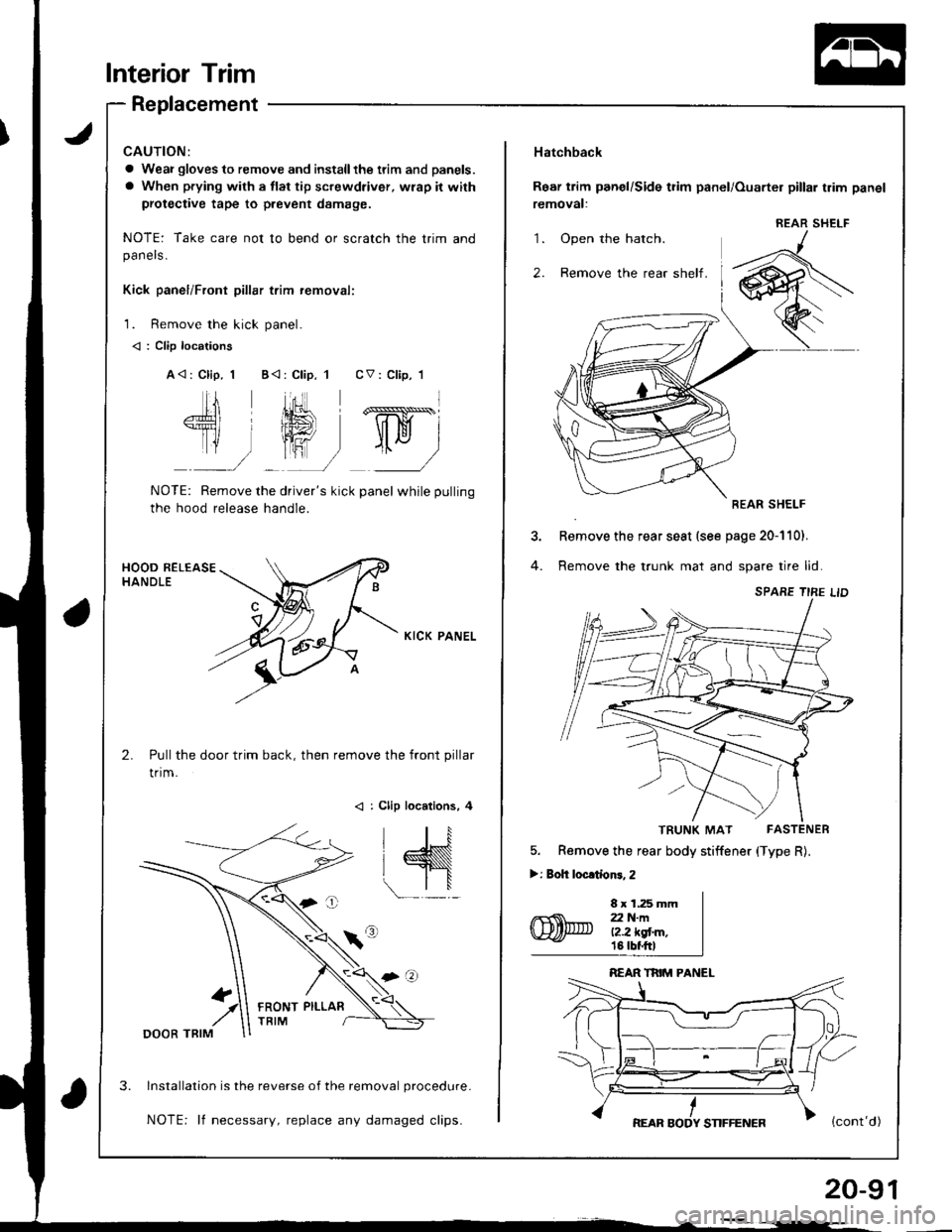
Replacement
a Weai gloves to remove and installthe ttim and panels.
a When prying with a flat tip screwdriver, wrap it with
protective tape to prevent damage.
NOTE: Take care not to bend or scratch the trim andpanels.
Kick panel/Front pillar trim removali
1. Remove the kick panel.
< : Clip locations
A<: Clip, 1 B<:Clip, 1 CV: Clip,'l
fl,ffi,ry
NOTE: Remove the driver's kick panel while pulling
the hood release handle.
KICK PANEL
Pull the door trim back, then remove the front pillar
trim.
< : Clip locations, 4
lnstallation is the reverse of the removal procedure.
NOTE: lf necessary, replace any damaged clips.
FRONT PILLAR
'1.
2.
Hatchback
Rear trim panel/Side t?im panel/Ouarter pillar trim panel
removal:
REAR SHELF
Remove the rear seat (see page 20-110).
Remove the trunk mat and spare tire lid
TRUNK MAT FASTENER
5. Remove the rear body stiffener (Type R).
>: Boh locltionr, 2
8 x 1.25 mmZ2 N-ml?.2 kgt m,18 tbf.ftl
REAR SHELF
20-91
Page 907 of 1681
lnterior Trim
Replacement (cont'd)
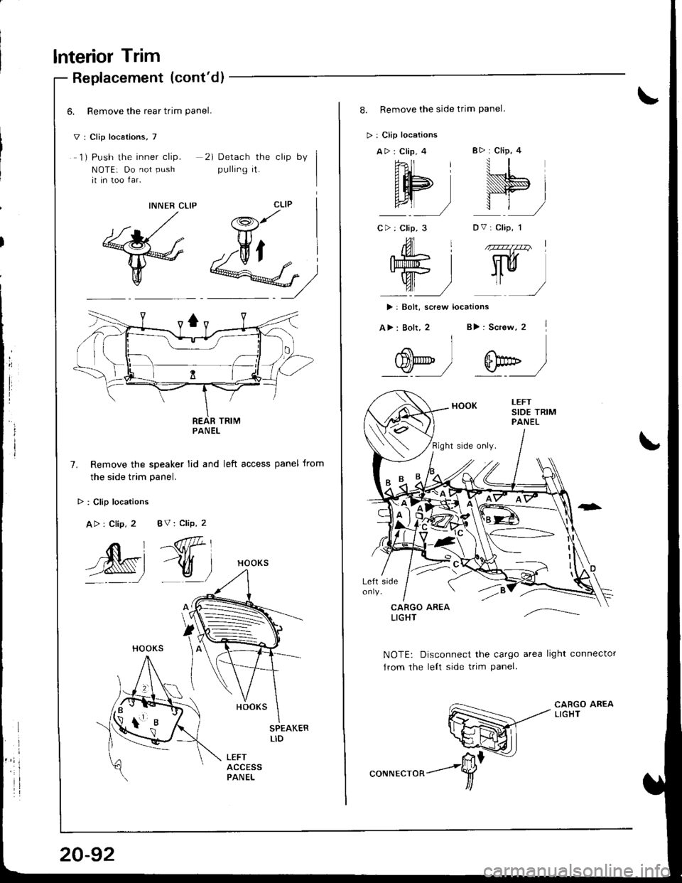
6. Remove the rear trim Panel.
V: Clip locations, 7
1) Push the inner clip.
NOTE: Do not PUshii in too far.
2) Detach the clip by
pulling it.
CLIPINNER CLIP
@M)
Remove the speaker lid and left access panel from
the side trim Danel.
> : Clip locations
Atr : Clip, 2
,^*i--_ l
HOOKS
HOOKS
HOOKS
SPEAKERLID
LEFTACCESSPANEL
PANEL
BV: Clip, 2
-@P,,
-v_)
.1
.oK=
tLh-
8. Remove the side trim Panel
> : Clip locations
A>: Clip, 4 B> : CliP, 4
hll rll
AH sl
g) t)
C>: Clip, 3 DV: clip, 1
ill 1 zz77z7v I
WI Wy'/"_/
>: Bolt, screw locations
A>: Bolt, 2 B): Screw, 2 |
I.4 .\
w) w__)
NOTE: Disconnect the cargo area light connector
Jrom the lelt side trim Panel.
CARGO AREALIGHT
Page 908 of 1681
9.
10.
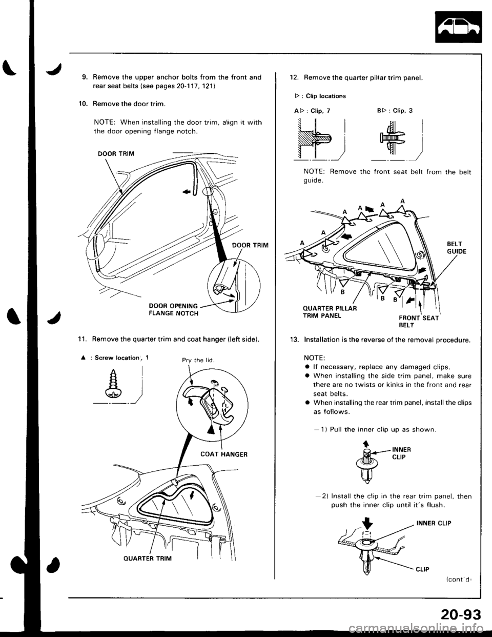
Remove the upper anchor bolts from the front and
rear seat belts (see pages 20-1 '17, 121)
Remove the door trim.
NOTE: When installing the door trim, align it with
the door opening flange notch.
Remove the quarter trim and coat hanger (left side).
: Screw location, 1
11.
lPry the lid.
12. Remove the quarter pillar trim panel.
> : Clip locations
A> : Clip, 7B>: Clip, 3
W;
.ML
W
NOTE: Remove the lront seat belt lrom the beltgurde-
BELT
'13. Installation is the reverse of the removal procedure.
NOTE:
a lf necessary, replace any damaged clips.
a When installing the side trim panel, make sure
there are no twists or kinks in the front and rear
seat belts.
a When installing the rear trim panel, install the clips
as follows.
1) Pull the inner clip up as shown.
tQ---INNER
/dm!r. cLrP
\7
u
2) Install the clip in the rear trim panel, then
push the inner clip until it's tlush.
INNER CLIP
(cont d
20-93
Page 909 of 1681
lnterior Trim
II
I
)
,/lCENTER PILLARLOWER TRIM
w
Replacement (cont'dl
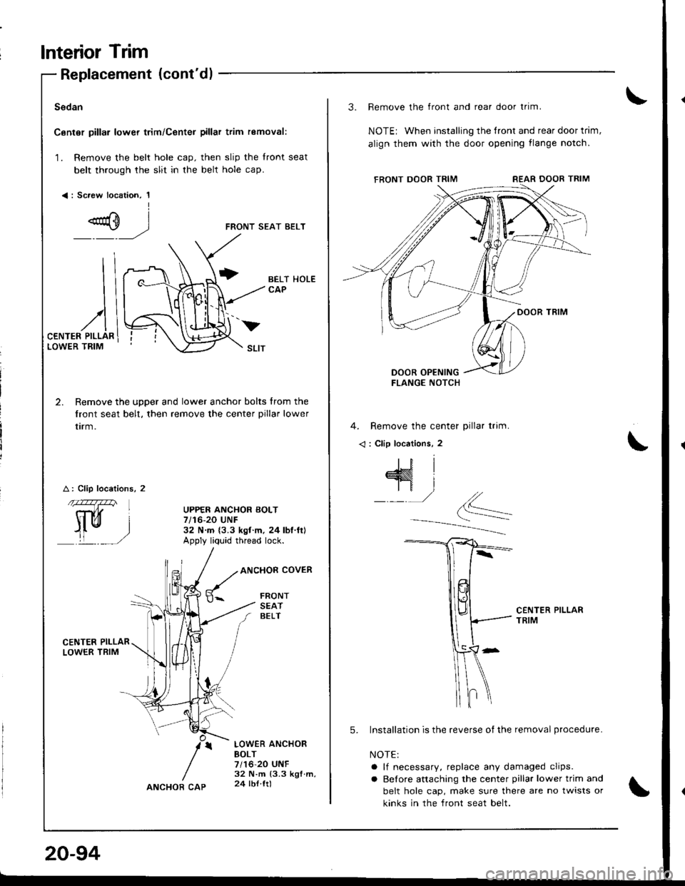
Sedan
Canter pillar lower trim/Center pillar trim removal:
1. Remove the belt hole cap. then slip the front seat
belt through the slit in the belt hole cap.
<: Sc.ew location, 1I
FRONT SEAT BELT
2. Remove the upper and lower anchor bolts from the
front seat belt, then remove the center pillar lower
trrm.
A: Clip locations, 2
CENTER PII-LARLOWER TRIM
BELT HOLECAP
UPPER ANCHOR BOLT7/16-20 UNF32 N.m {3.3 ksf.m. 24lbl.ft}Apply liq'rid thread lock.
ANCHOR COVER
FRONTSEATBELT
LOWER ANCHOBBOLT7/16-20 UNF32 N.m (3.3 kgf.m,24 lbl ttl
v
20-94
ANCHOR CAP
3. Remove the front and rear door trim.
NOTEr When installing the tront and rear door trim,
align them with the door opening flange notch,
4. Remove the center pillar trim.
< : Clip locations, 2
CENTER PILLARTRIM
5. Installation is the reverse of the removal procedure.
NOTE:
a lf necessary, replace any damaged clips.
a Before attaching the center pillar lower trim and
belt hole cap, make sure there are no twists or
kinks in the front seat belt.
Page 910 of 1681
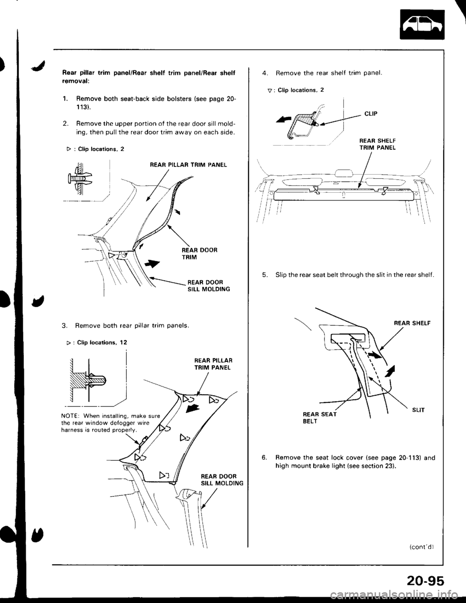
Rear pillar trim panel/Rsar shelf trim panel/Real shelt
removal:
1. Remove both seat-back side bolsters {see page 20-
113).
2. Remove the upper portion of the rear door sill mold-
ing, then pull the rear door trim away on each side.
> : Clip locations, 2
REAR PILLAR TRIM PANEL
SII-I MOLDING
3. Remove both rear pillar trim panels.
> | Clip locations, 12
NOTE: When installing, make surethe rear window defogger wireharness is routed properly.
1
I
,
4. Remove the rear shell trim panel.
V: Clip locations, 2
5. Slip the rear seat belt through the slit in the rear shelf.
REAR SHELF
Remove the seat lock cover (see page 20 113) and
high mount brake light (see section 23).
20-95