HONDA INTEGRA 1998 4.G Workshop Manual
Manufacturer: HONDA, Model Year: 1998, Model line: INTEGRA, Model: HONDA INTEGRA 1998 4.GPages: 1681, PDF Size: 54.22 MB
Page 861 of 1681
Doors
Glass Adjustment (cont'dl
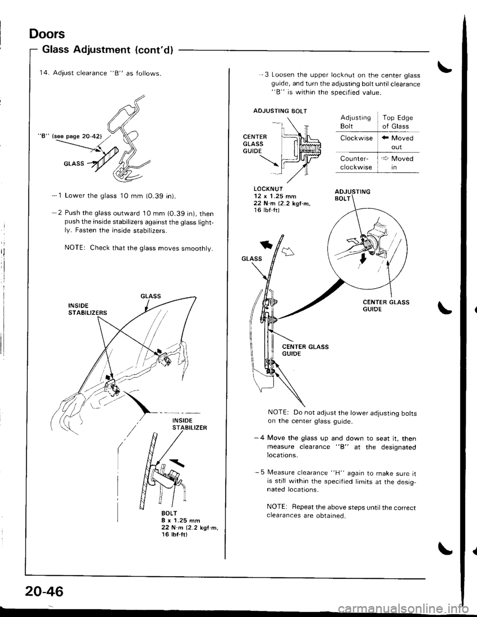
'14. Adiust clearance "B" as Jollows.
"8" lsee page 20-421
- 1 Lower the glass 1O mm (0.39 in).
2 Push the glass outward 10 mm 10.39 in), thenpush the inside stabilizers against the glass light-ly. Fasten the inside stabrIzers.
NOTEr Check that rhe glass moves smoothly.
BOLT8 x 1.25 mm22 N.m (2.2 kgf.m,'t6 tbt.fr)
20-46
-
-.\
CENTER [L\LGLAss lilffiGUTDE I li$lliun
\fiJrtrlAl-,/"
.-3 Loosen the upper locknut on the center glassguide, and turn the adjusting bolt until clearance"B" is within the specified value.
ADJUSTING BOLT
LOCKNUT
22 N.m 12.2 kgt tn,16 lb{.ttl
*
GLASS
NOTE: Do not adjust the lower adjusting boltson the center glass guide.
-4 Move the glass up and down to seat jt, then
measure clearance "B" at the designatedlocations.
- 5 Measure clearance "H" again to make sure itis still within the specified limits ar the desig,nated locations.
NOTE: Repeat the above steps until the correctclearances are obtained.
Top Edge
of Glass
Page 862 of 1681
15.
to,
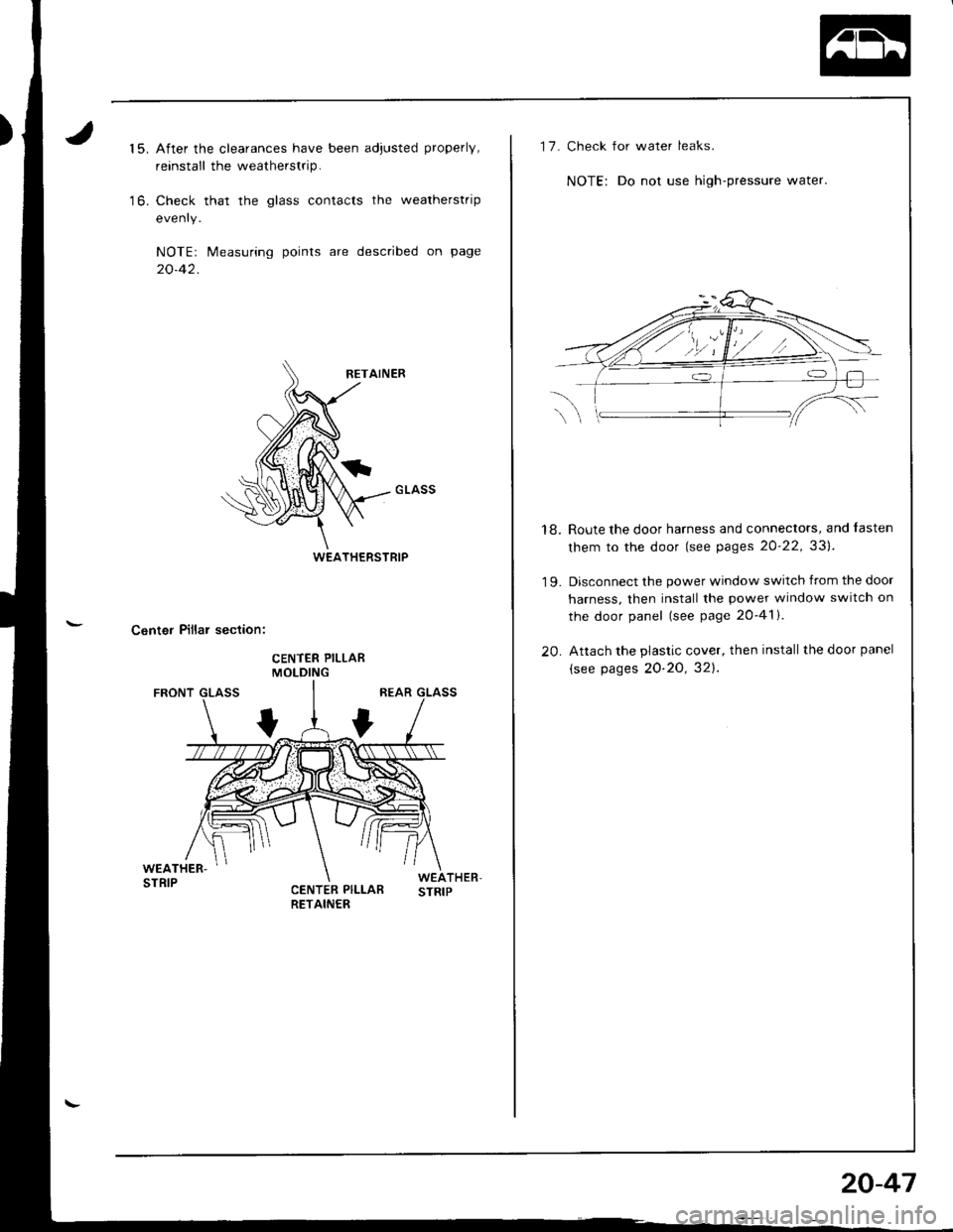
After the clearances have been adjusted properly,
reinstall the weatherstrip.
Check that the glass contacts the weatherstrip
evenry.
NOTEr Measuring points are described on page
20-42.
Center Pillar section:
WEATHERSTRIP
17.Check for water leaks.
NOTE: Do not use high-pressure water.
18. Route the door harness and connectors, and lasten
them to the door (see pages 20'22,331.
'19. Disconnect the power window switch from the door
harness, then install the power window switch on
the door panel (see page 20-41).
20. Attach the plastic cover, then install the door panel
(see pages 2O'2o, 321.
20-47
Page 863 of 1681
Doors
Position Adjustment
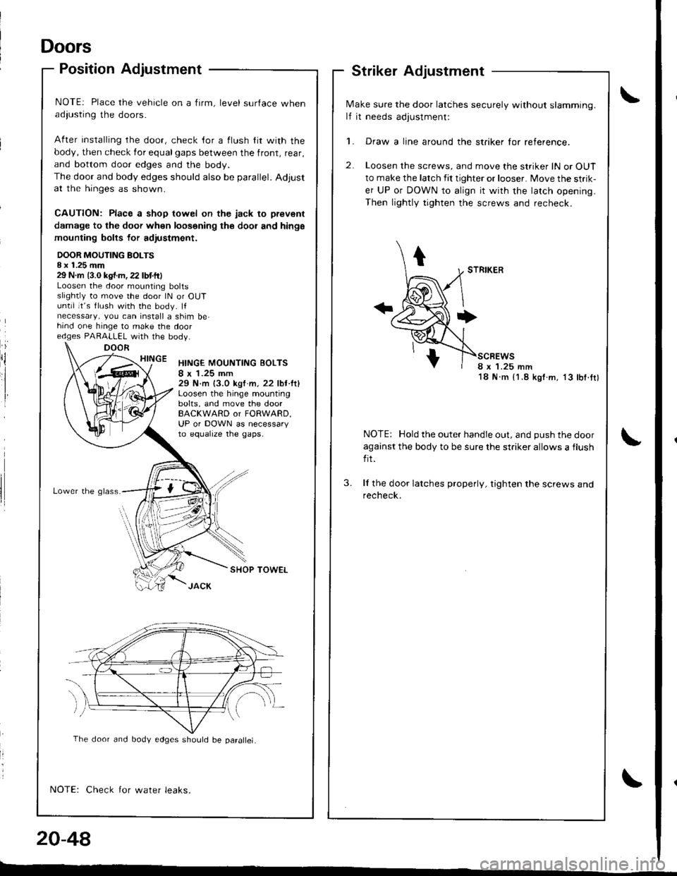
NOTE: Place the vehicle on a firm, level surface whenadiusting the doors.
After installing rhe door, check {or a flush lir with the
body, then check for equalgaps between the front, rear,
and bottom door edges and the body.
The door and body edges should also be parallel. Adjustat the hinges as shown.
CAUTION: Place a shop towel on the jack to prevenl
damage to the doof when loosening the dool and hinge
mounting bolts for adiustmont.
DOOR MOUTING BOLTSI x 1.25 mm29 N.m (3.0 kgt.m,22 lbtft)Loosen the door mounting boltsslightly to move the door lN or OUTuntil it's flush with the body. lfnecessary, you can install a shim be-hind one hinge to make the dooredges PARALLEL with the bodV.
HINGEHINGE MOUNTING BOLTS8 x 1.25 mm29 N.m (3.0 kgf m, 22 lbt.lt)Loosen the hinge mountingbolts, and move the doorBACKWARD or FORWARD,UP or DOWN as necessaryto equalrze tne gaps,
Lower the g lass.
SHOP TOWEL
Check for water leaks.
.iDOOR
N,4ake sure the door latihes securely without slamming.
lf it needs adjustment:
1. Draw a line around the striker lor reference.
2. Loosen the screws, and move the striker lN or OUT
to make the latch fit tighter or looser. Move the strik-
er UP or DOWN to align it with the latch opening.
Then lightly tighten the screws and recheck.
scBEws8 x '1.25 mm18 N.m {1.8 kgf.m. 13 lbf.tt}
NOTE: Hold the outer handle out, and push the door
against the body to be sure the striker allows a flush
fit.
ll the door latches properly, tighten the screws andrecheck.
3.
20-48
The door and body edges should be parallel.
-"
Page 864 of 1681
Mirrors
2.
Power Mirror Replacement
Hatchback
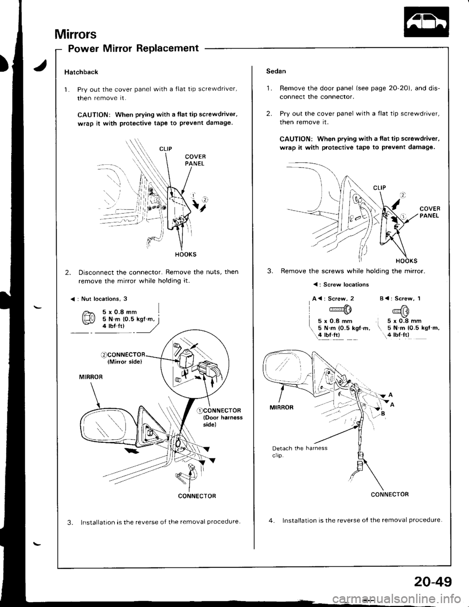
1. Pry out the cover panel with a Ilat tip screwdriver,
then remove it.
CAUTION: When piying with a tlat tip screwdriver,
wrap it with protgctive tape to prevent damage.
Disconnect the connector. Remove the nuts, then
remove the mirror while holding it.
< : Nut locations, 3
(Mirror side)
MIRROR
ocoNNECTOR(Ooor harnessside)
CONNECTOR
3. Installation is the reverse of the removal procedure.
HOOKS
5xo.8mm I
*l.
Sedan
1. Remove the door panel (see page 20-201, and dis-
connect the connector.
2. Pry out the cover panel with a flat tip screwdriver,
then remove rt.
CAUTION: When prying with a tlat tip screwdriver.
wrap it with protective tape to prevent damage.
COVEBPANEL
3. Remove the screws while holding the mirror.
< : Screw locations
A<: Screw, 2
qu
5xO.8mm
5 N.m {O.5 kgf.m, \..'llYJ1l
5x0.8mm5 N.m 10.5 kgl m,...4 tbt.tt)
CONNECTOR
4. Installation is the reverse ot the removal procedure.
B<: Screw, 1
20-49
Page 865 of 1681
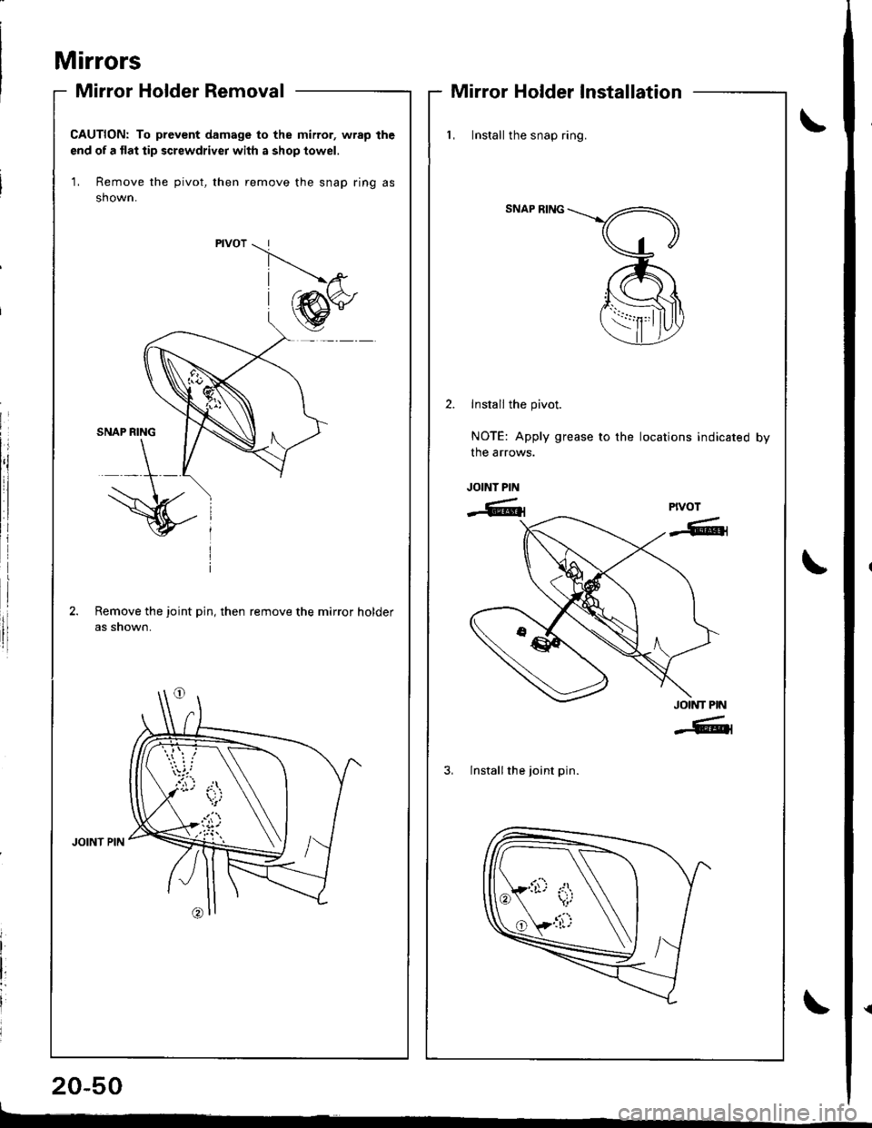
Mirrors
Mirror Holder Removal
20-50
Mirror Holder Installation
CAUTION: To prevent damage to the mirror, wrap the
end of a flat tip screwdriver with a shop towel.
1, Remove the pivot, then remove the snap ring as
shown.
Remove the joint pin, then remove the mirror holder
as snown.
_.'ta,i
{i'}
l, Install the snap ring.
SNAP RING
Install the pivot.
NOTE: Apply grease to the locations indicated by
the arrows.
JOINT PIN
-6lrPIVOT
-6t1
JOINT PIN
-6tl
3, lnstall the joint pin.
Page 866 of 1681
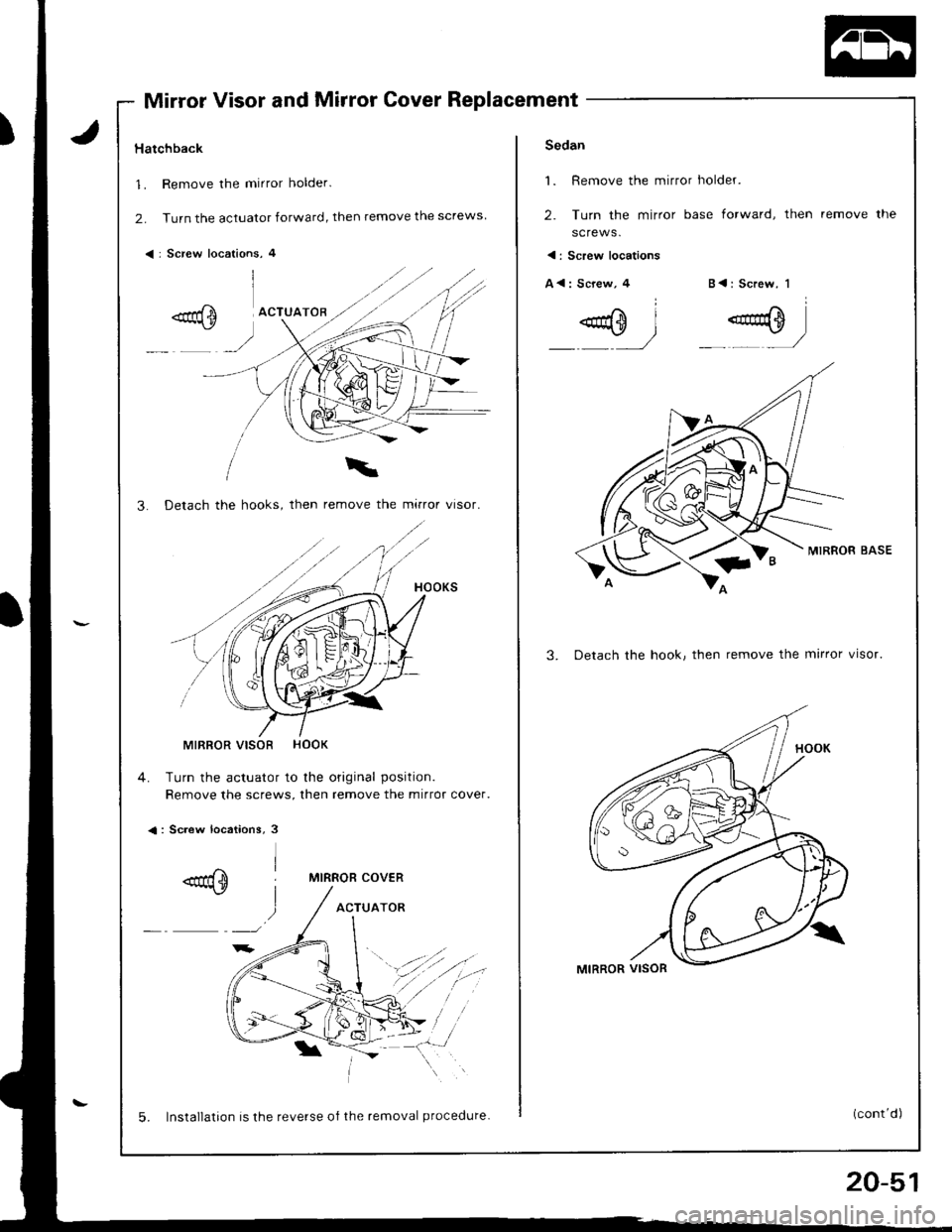
Mirror Visor and Mirror Cover Replacement
Hatchback
1. Remove the mirror holder.
2. Turn the actuator forward, then remove the screws
< : Screw locations, 4
3. Detach the hooks, then remove the mirror visor.
MIRROR VISOR HOOK
4. Turn the actuator to the original position.
Remove the screws, then remove the mirror cover.
<: Screw locations, 3
MIRROR COVER
ACTUATOR
5. Installation is the reverse of the removal procedure.
20-51
Sedan
1. Remove the mirror holder.
2. Turn the mirror base forward, then
screws.
remove the
< : Screw locations
A<: Screw,4B<: Screw, 1
MIRROR BASE
3. Detach the hook, then remove the mirror visor.
Page 867 of 1681
![HONDA INTEGRA 1998 4.G Workshop Manual Replacement (contd)
4. Remove the actuator, then remove the screws.
<: Screw locations
A<: Screw, 3 B<: Screw, 2C { : Screw, 1
.aqm I- r/
.0=-l .g}_,,]
5.Turn the mirror base as shown, then remove HONDA INTEGRA 1998 4.G Workshop Manual Replacement (contd)
4. Remove the actuator, then remove the screws.
<: Screw locations
A<: Screw, 3 B<: Screw, 2C { : Screw, 1
.aqm I- r/
.0=-l .g}_,,]
5.Turn the mirror base as shown, then remove](/img/13/6069/w960_6069-866.png)
Replacement (cont'd)
4. Remove the actuator, then remove the screws.
<: Screw locations
A<: Screw, 3 B<: Screw, 2C { : Screw, 1
.aqm I- r'/
'.0=-l .g}_,,]
5.Turn the mirror base as shown, then remove Ine mtr
ror cover
MIRROR AASE
6. Installation is the reverse oI the removal procedure.
ACTUATOR
MIRROR COVEB
Mirrors
Mirror Visor and Mirror CoverRearview Mirror Replacement
:
rl
rl
I
20-52
L
1. Pry the cover off using the end of a flat tip screw-
drive r.
CAUTION: To prevent damage to the mirror and
cover, wrap the end ol the screwdriver with a shop
towel.
2. Remove the screws, then remove the rearview
mirror.
REARVIEWMIRROR
3. lnstallation is the reverse of the removal orocedure.
SHOP TOWEL
Page 868 of 1681
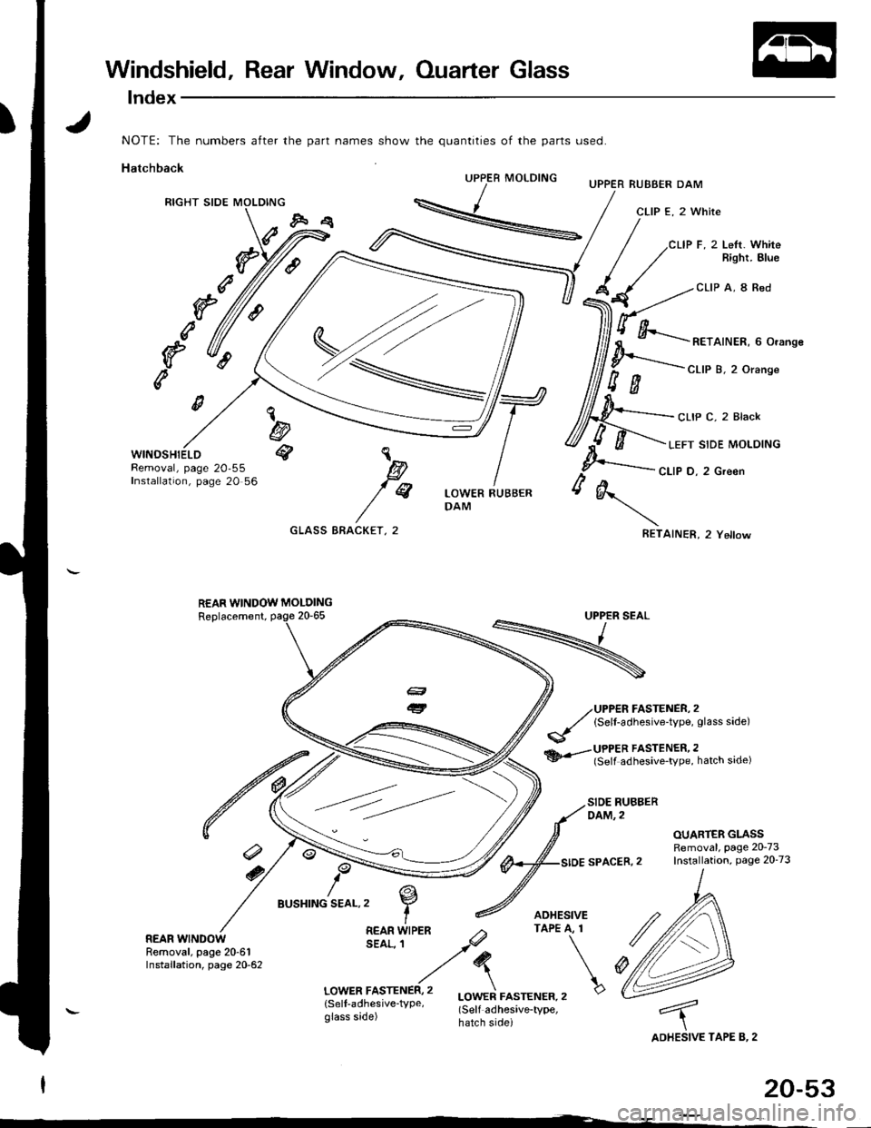
Windshield, Rear Window, Ouarter Glass
lndex
part names show the quantities of the parts Lrsed.
UPPER MOLDINGUPPER RUBBER DAM
CLIP E, 2 White
CLIP F, 2 Lett. WhiteBight. Blue
CLIP A, 8 Red
c
f(
RETAINER, 6 Orange
CLIP B, 2 Orange
CLIP C, 2 Black
LEFT SIDE MOLDING
CLIP D, 2 Green
AINER, 2 Yellow
WINOSHIELDRemoval, page 20,55Installation, page 20 56
REAR
GLASS BRACKET, 2
,^
,r"
A
RET
a
REAR WINDOW MOLDING
UPPER FASTENER, 2(Self-adhesive-type, glass side)
UPPER FASTENER,2(Self adhesive_type, hatch side)
SIDE RUBBERDAM, 2
OUARTER GLASSRemoval, Page 20-73
SPACER,2 Installation, Page 20-73
TAPE B, 2ADHESIVE
/
Ar-/
I
BUSHING SEAL.2
Removal, page 20-61Installation, page 20-62
NOTE: The numbers after the
Hatchback
RIGHT SIDE MOLDING
'l
@q
a
e,
Page 869 of 1681
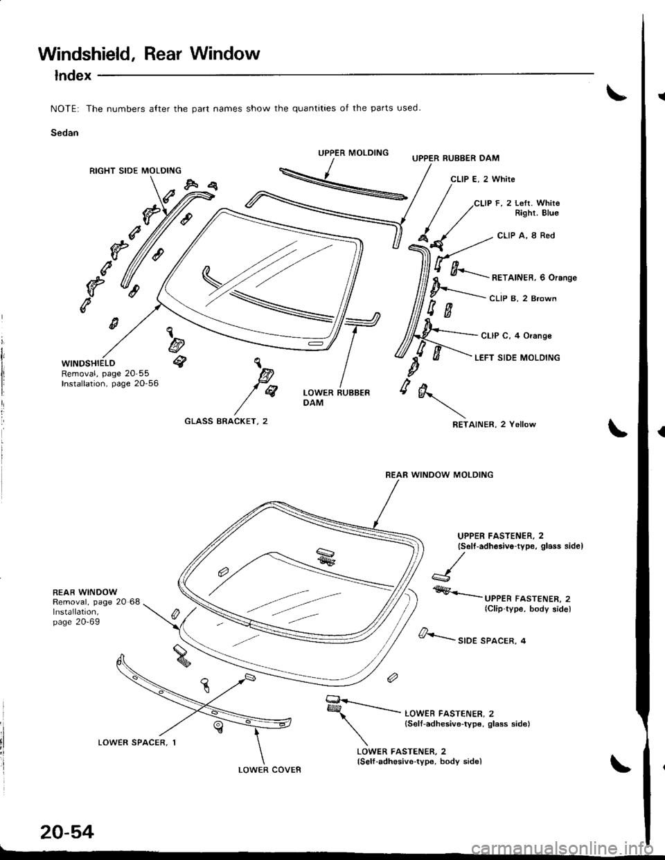
Windshield, Rear Window
lndex
NOTE: The numbers alter the part names show the quantities of the parts used.
Sedan
UPPER MOLDING
RIGHT SIDE MOLDING
g
e
e
WINDSHIELDRemoval, page 20-55Installation, page 20-56
bq
BEAR WINDOWRemoval, page 20 68Installation,page 20-69
UPPER RUBBER DAM
CLIP E, 2 White
cLlP F, 2 Lefr. WhireRight. Elue
CLIP A, 8 Red
\
B)
fqLOWER RUBBERDAM
A
\
RET
g
REAR WINDOW MOLDING
GLASS BRACKET, 2AINER, 2 Yellow
UPPER FASTENER, 2(Self -adhesivo-type, glass side)
#,Krrr*
FA.TENER, 2(Clip-type, body side)
LOWER COVER
20-54
&....-r,o, sPAcER, 4
q*-------..- LowEB FA'TENER, 2
{Self-adhesive-typ€,slasssid€)
LOWER FASTENER, 2(Self-adhosive-type, body sidel
Page 870 of 1681
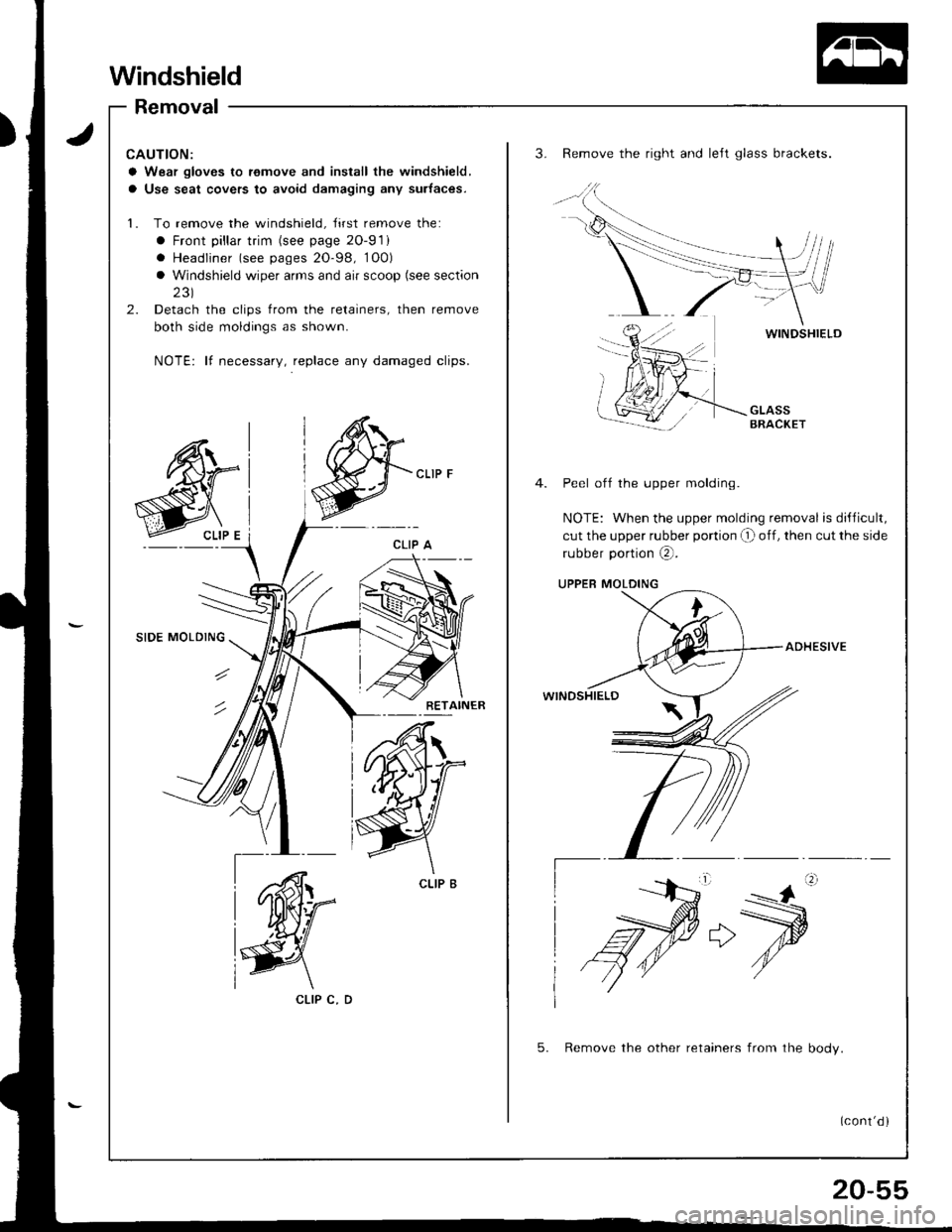
Windshield
Removal
CAUTION:
a Wear gloves to remove and inslall the windshield,
a Use seat covers to avoid damaging any surtaces.
1. To remove the windshield, Jirst remove the:
a Front pillar trim (see page 2O-91)
. Headliner (see pages 20-98, 1O0)
a Windshield wiper arms and air scoop (see section
231
2. Detach the clips from the retainers, then remove
both side moldings as shown.
NOTE: lf necessary, replace any damaged clips.
3. Remove the right and left glass brackets.
WINOSHIELD
Peel off the upper molding.
NOTE: When the upper molding removal is dillicult,
cut the upper rubber portion O off, then cut the side
rubber portion @.
UPPER MOLDING
ADHESIVE
WINDSHIELD
5. Remove the other retainers from the bodv.
CLIP C, D
(cont'd )