HONDA INTEGRA 1998 4.G Workshop Manual
INTEGRA 1998 4.G
HONDA
HONDA
https://www.carmanualsonline.info/img/13/6069/w960_6069-0.png
HONDA INTEGRA 1998 4.G Workshop Manual
Trending: fuse box diagram, park assist, throttle valve, diagram, wiper blades, fuel additives, coolant capacity
Page 911 of 1681
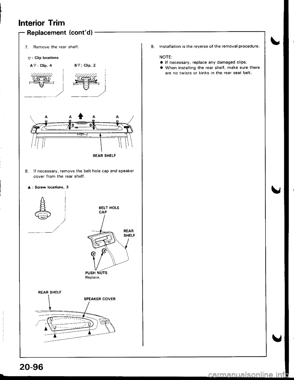
lnterior Trim
V : Clip locaiions
AV : Clip, 4
A\-=:-1.,/
Replacement (cont'd)
7. Remove the rear shelI.
BV: Clip, 2
*, . '
\o.=lt. lffif i=-E:
ru: j
,rt -- t/
8. lf necessary, remove the belt hole cap and speaker
cover from the rear shelf.
: Screw locations, 3
BELT HOLECAP
PUSH
REAR SHELF
20-96
9.lnstallation is the reverse of the removal procedure.
NOTE:
a It necessary, replace any damaged clips.
a When installing the rear shelf, make sure there
are no twists or kinks in the rear seat belt.
Page 912 of 1681
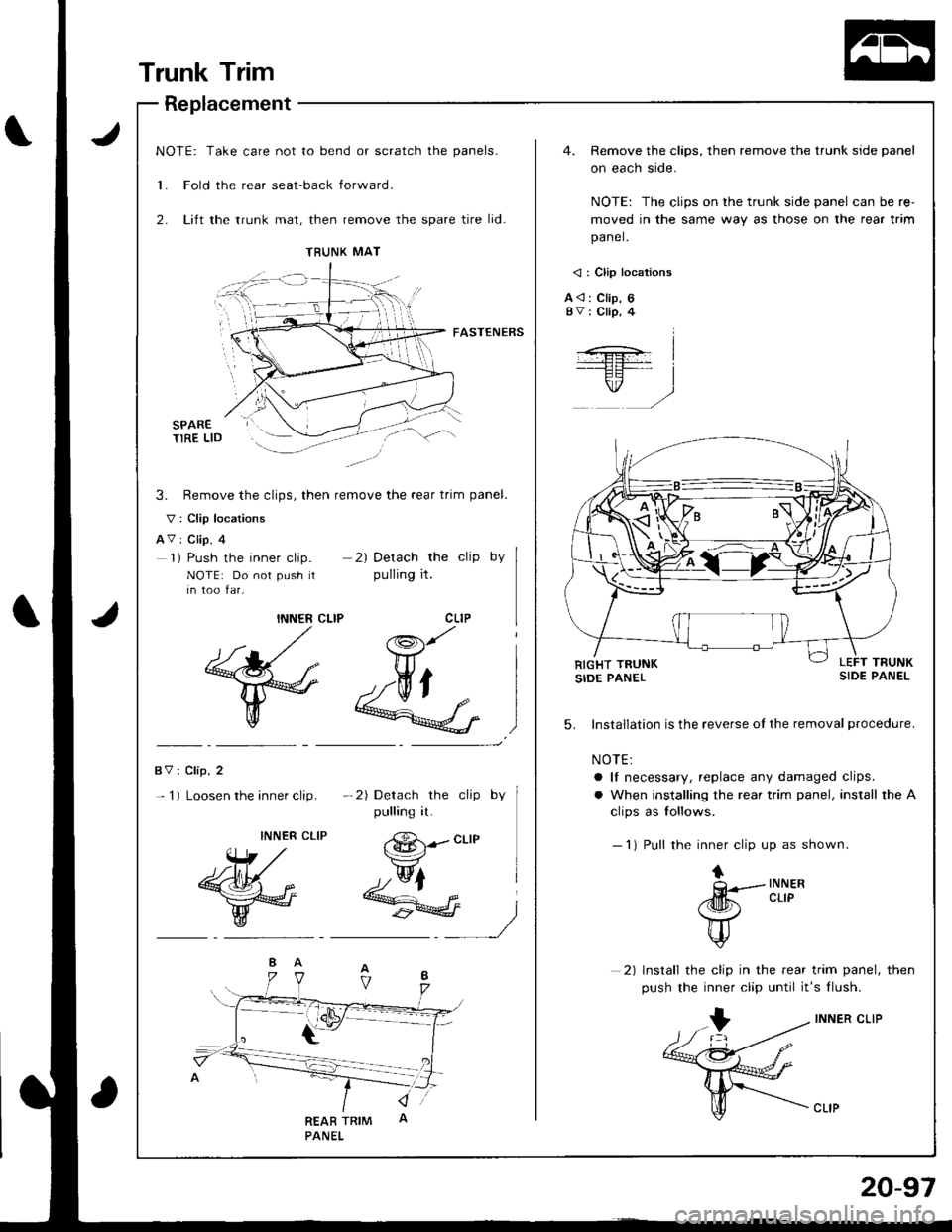
NOTE: Take care not to bend or scratch the panels.
1. Fold the rear seat-back forward.
2. Lift the trunk mat, then remove the spare tire lid-
4. Remove the clips, then remove the trunk side panel
on each side.
NOTE: The clips on the trunk side panel can be re-
moved in the same way as those on the rear trim
panel.
< : Clip locations
A<: Clip, 6BV : Clip, 4
FASTENERS
3. Remove the clips, then remove the rear trim panel.
V: Clip locations
AV: Clip, 4'l ) Push the inner clip.
NOTE: Do not push rtin too far,
2) Detach the clip by
pulling it.
INNER CLIP
ffi
co.r/ I
&l5.
BV: Clip, 2
- 1) Loosen the inner clip.-2) Detach the clip by
pulling it.
Installation is the reverse of the removal procedure.
NOTE:
a It necessary, replace any damaged clips.
a When installing the rear trim panel, install the A
clips as follows.
- 1) Pull the inner clip up as shown.INNER
Wr ,/
&M*
W
@1--crte
&
+INNERCLIPff
Y
2) lnstall the clip in the rear trim panel, then
push the inner clip until it's flush.
INNER CLIP
TBUNK MAT
Trunk Trim
Replacement
20-97
Page 913 of 1681
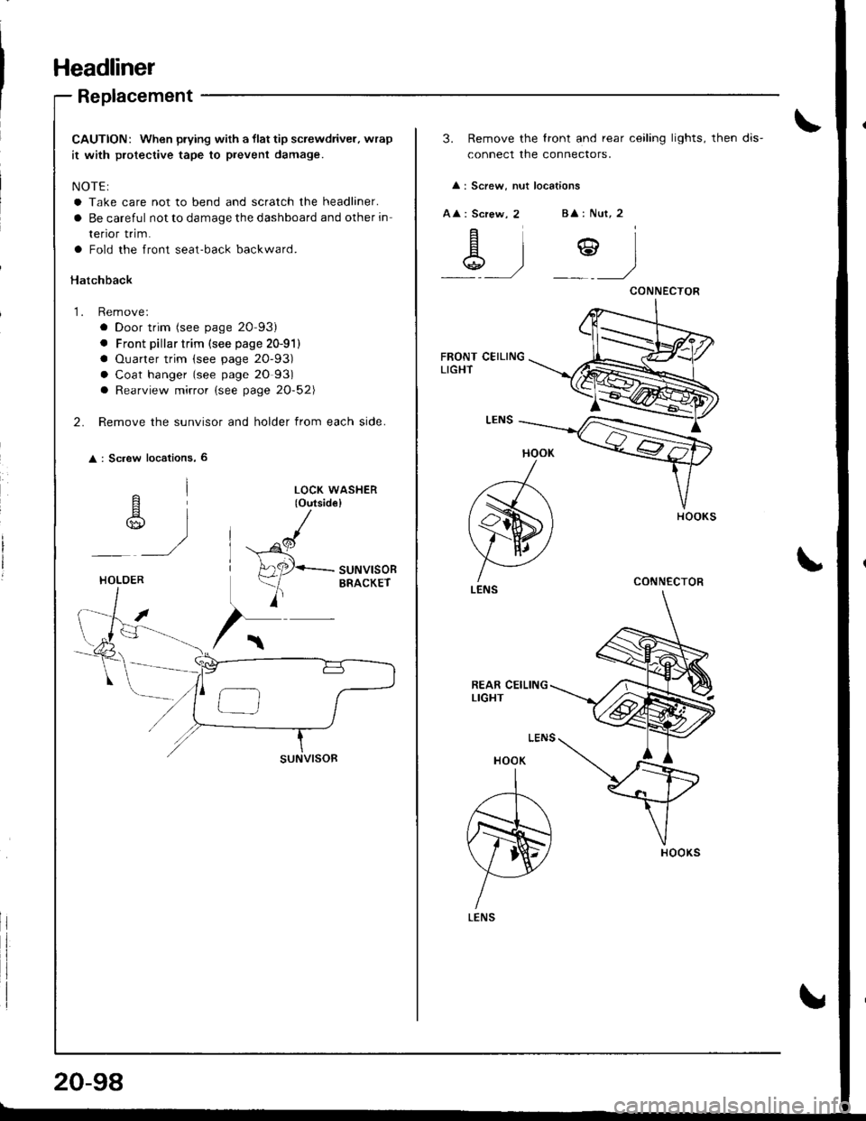
Headliner
Replacement
CAUTION: When prying with a llat tip screwdriver. wrap
it with protective tape to prevent damage.
NOTE:
a Take care not to bend and scratch the headliner.
a Be careful not to damage the dashboard and other in
renor rr|m.
a Fold the front seat-back backward.
Hatchback
1. Remove:
a Door trim (see page 20-93)
. Front pillar trim (see page 20-91)
a Ouarter trim (see page 20-93)
a Coat hanger (see page 20 93)
a Rearview mirror (see page 20-52\
2. Remove the sunvisor and holder from each side.
: Sc.ew locations, 6
^l
r$,,
)
LOCK WASHER(o{rtsid€}
^cl
H
A2P-suNvlsoR
)
ERACKErHOLOER
20-98
3. Remove the lront and rear ceiling lights, then dis-
connect the connectors.
: Screw, nut locations
A : Screw, 2B : Nut, 2
\g .)Y)
HOOK
)
(s)
V AI ./
LENS
HOOK
A
N)
YLENS
CONNECTOR
CONNECTOR
Page 914 of 1681
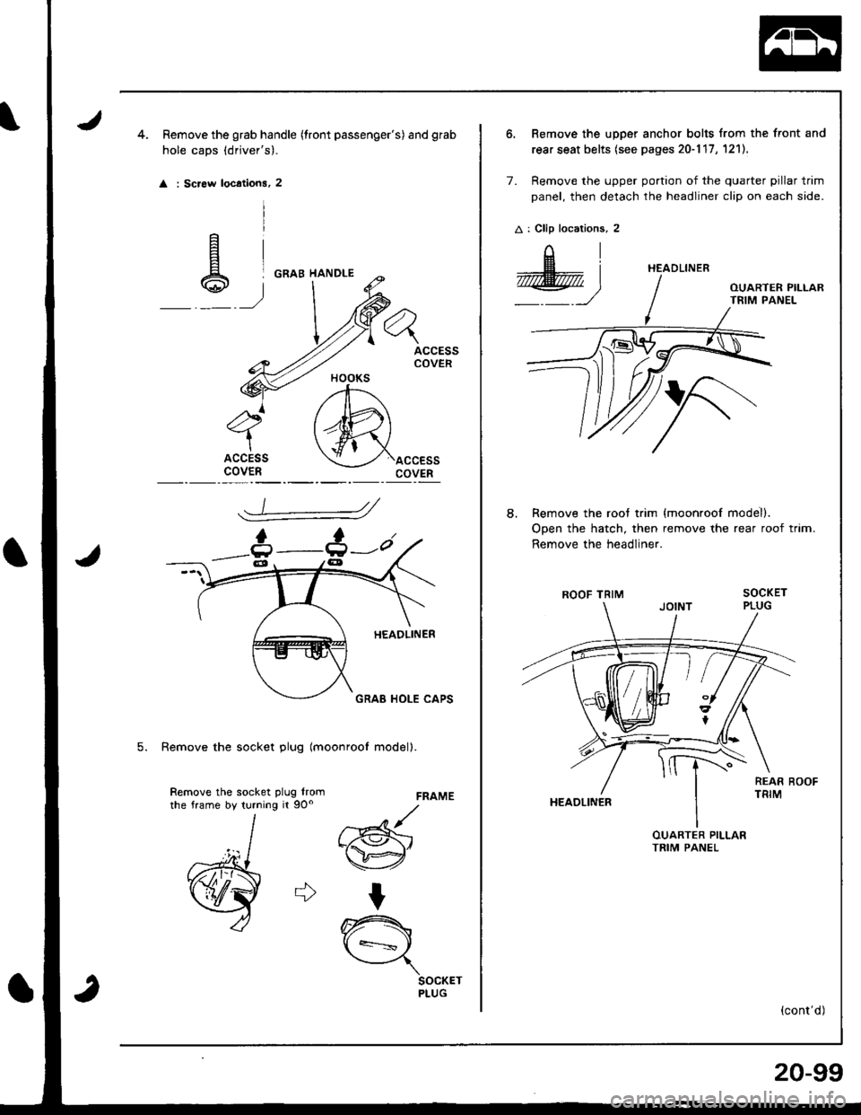
Remove the grab handle (tront passenger's) and gfab
hole caps (drjver's).
: Screw locations, 2
ACCESSCOVER
ACCESScovEnaccEssCOVER
FRAME
d
w"
t
A
\={
SOCKETPLUG
5. Remove the socket plug lmoonroof modell.
Remove the socket plug lromrhe frame by turning it 9Oo
6. Remove the upper anchor bolts from the front and
rear seat belts (see pages 20-117 , 1211.
7. Remove the upper portion of the quarter pillar trim
panel, then detach the headliner clip on each side.
A : Clip locations, 2
AI
@)
Remove the roof trim
Open the hatch, then
Remove the headliner.
ROOF TRIM
HEAOLINER
{moonroof model).
remove the rear roof trim.
(cont'd)
HEADLINER
8.
20-99
Page 915 of 1681
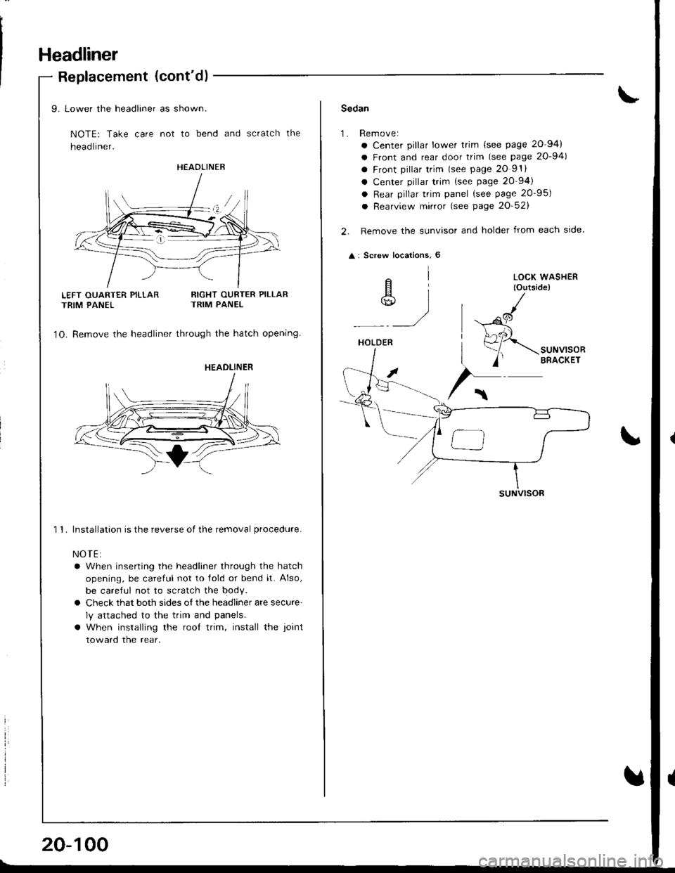
Headliner
Replacement (cont'd)
LEFT OUARTER PILLARTRIM PANEL
9. Lower the headliner as shown.
NOTE: Take care not to bend and scratch the
head liner.
RIGHT OURTER PILLARTRIM PANEL
1O. Remove the headliner through the hatch opening
1 1. Installation is the reverse of the removal procedure.
NOTE:
a When inserting the headliner through the hatch
opening, be careful not to lold or bend it. Also,
be careful not to scratch the body.
a Check that both sides o{ the headliner are secure'
ly attached to the trim and panels.
a When installing the rool trim, install the ioint
toward the rear.
HEAOLINER
HEADLINER
20-100
Sedan
1.Rem ove:
a Center pillar lower trim {see page 20-94)
a Front and rear door trim (see page 20-94)
a Front pillar trim lsee page 20 9'.
a Center pillar trim {see page 20 94)
a Rear pillar trim panel (see page 20-95)
a Rearview mirror (see page 20 52)
Remove the sunvisor and holder from each side.
: Screw locations, 6
elA]*)
HOLDER
suNVlsoR
LOCK WASHER
lOutside)
,al
(
Page 916 of 1681
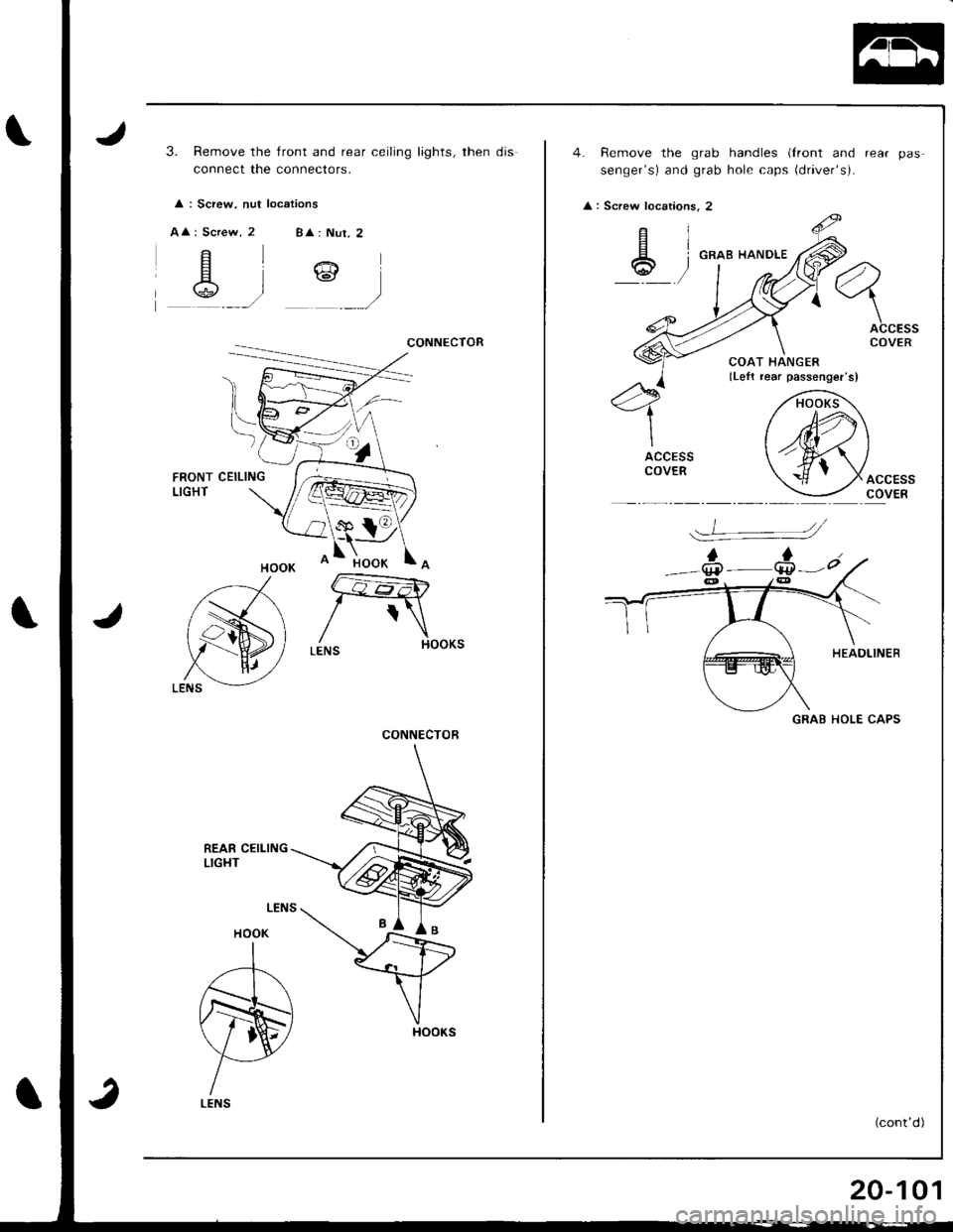
3. Remove the front and rear ceiling lights, then djs
connect the connectofs.
: Screw, nut locations
AA
CONNECTOR
FRONTLIGHTCEILING
REAR CEILINGLIGHT
HOOK
A
N
LENS
CONNECTOR
Remove the grab handles (Iront and
senger's) and grab holF caps {dl|ver'sr.
GRAB HANDLE
GRAE HOLE CAPS
Screw locations.
ciEI
6t
J-.
20-101
Page 917 of 1681
Headliner
Replacement (cont'd)
5.
6.
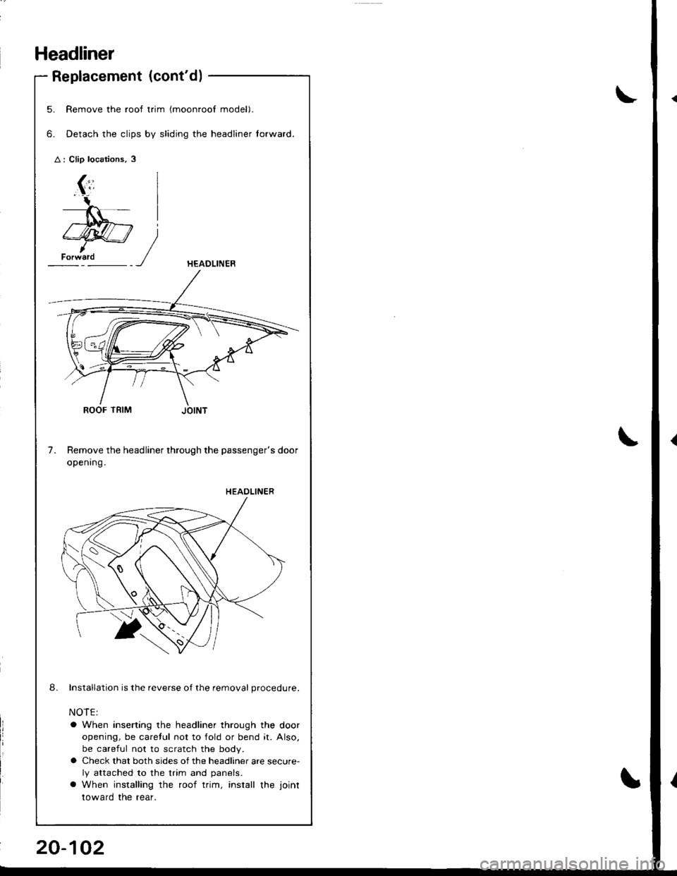
Remove the roof trim (moonroof model).
Detach the clips by sliding the headliner torward.
ROOF TRIM
Remove the headliner through the passenger's door
openrng.
Installation is the reverse of the removal procedure.
NOTE:
a When inserting the headliner through the door
opening, be caretul not to fold or bend it. Also,
be careful not to scratch the body.
o Check that both sides of the headliner are secure-
ly attached to the trim and panels.
a When installing the roof trim, install the joint
toward the rear.
)
7.
8.
HEAOLINER
HEAOLINER
Page 918 of 1681
Seats
FrontSeatRemcival
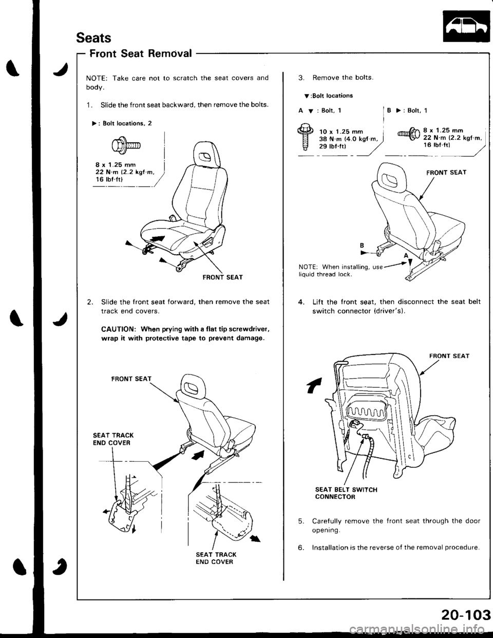
NOTE: Take care not to scratch the seat covers and
oooy.
1 . Slide the front seat backward, then remove the bolts.
>: Bolt locations, 2
3. Remove the bolts.
v:Bolt locations
A V: Bolt, 1I >:Bolr, 1
10 x 1.25 mm l38 N.m (4.0 kgJ m, J,":: J
8 x 1.25 mm22 N.m {2.2 kgt m,
:u",: -/
8 x 1.25 mm I22 N'm 12.2 kst m. )16 rbf.rt)_ /
NOTE: When installing, usey'
--RONT SEAT
2. Slide the front seat forward, then remove the seat
track end covers.
CAUTION: When p.ying with I llat tip screwdliver,
wrap it with protective tape to prevent damage.
liq0id thread lock.
Lift the lront seat, then disconnect the seat
switch connector {driver's).
belt
SEAT TRACKENO COVER
SEAT BELT SWITCHCONNECTOR
5. Carelully remove the front seat through the door
opening.
6. Installation is the reverse of the removal procedure.
Page 919 of 1681
Seats
Front Seat Replacement
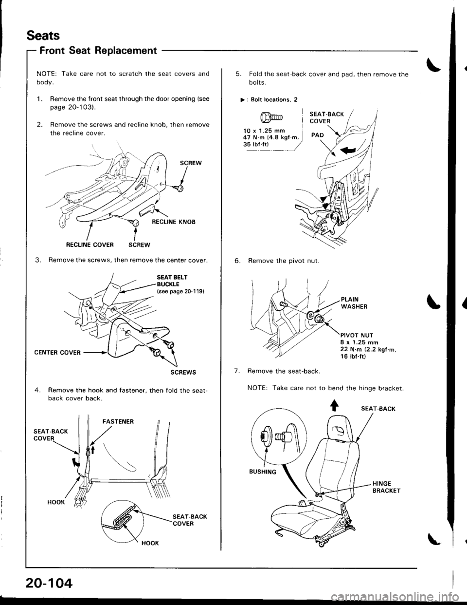
CENTER COVER
NOTEr Take care not to scratch the seat covers and
oooy.
l. Remove the front seat through the door opening (see
page 20-'103).
2. Remove the screws and recline knob, then remove
the recline cover.
SCREW
l-{O
BECLINE KNOB
3. Remove the screws, then remove the center cover.
SEAT BELTBUCKLE(see page 20-119)
scREws
4. Remove the hook and fastener, then fold the seat-back cover back.
RECLINE COVER SCREW
20-104
5. Fold the seat-back Qover and pad, then remove the
bo lts.
>: Boli locations, 2
SEAT.EACKCOVER
PAD
6. Remove the pivot nut.
PLAINWASHER
PIVOT NUT8 x 1.25 mm22 N.n (2.2 kgt m,'t 6 tbt.ttl
Remove the seat-back.
NOTE: Take care not to bend the hinge bracket.
10 x 1.25 mm47 N.m 14.8 kgf.m,3!'oli1 /
7.
+ sEAr-BAcK
-A\
@ )\
f\
Page 920 of 1681
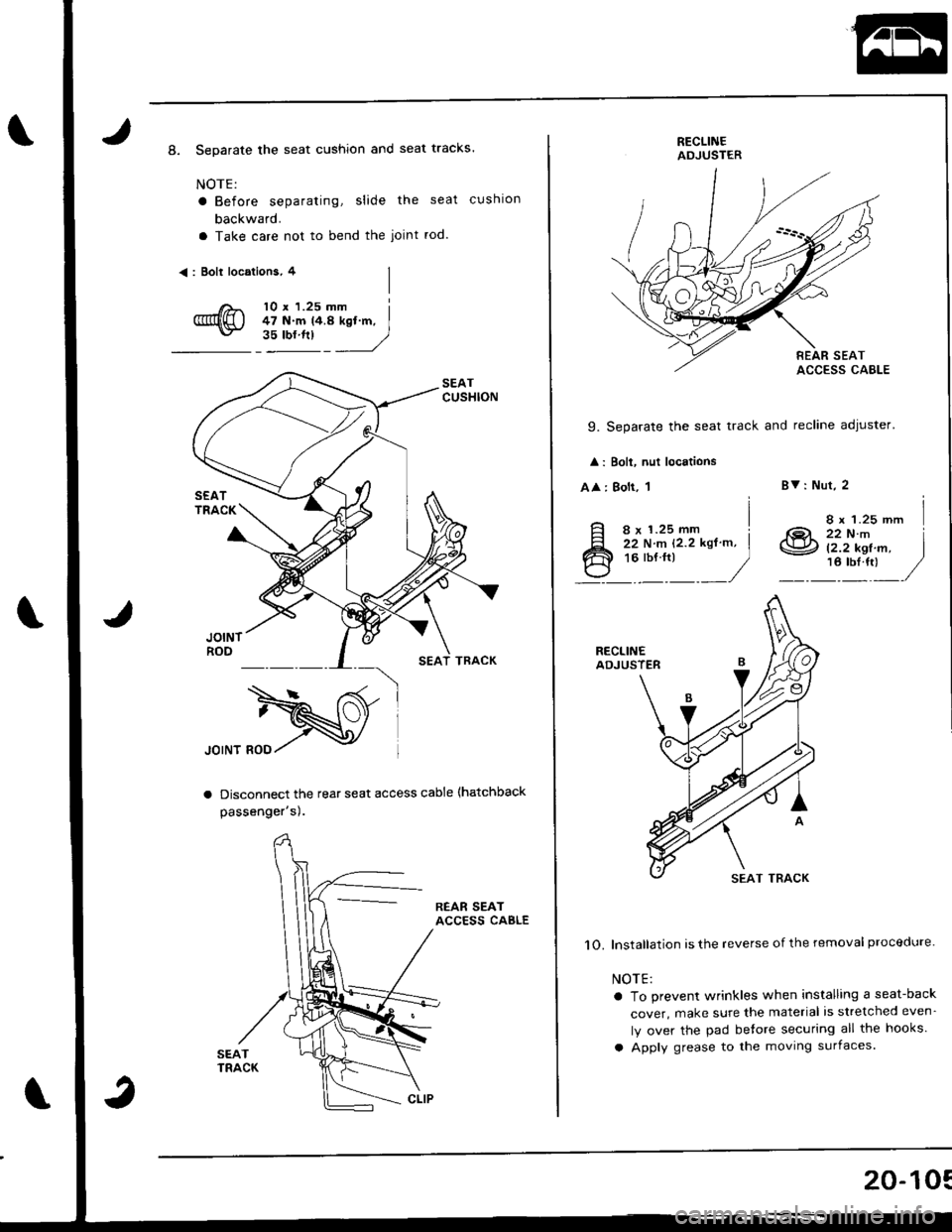
8. Separate the seat cushion and seat tracks.
NOTE:
a Before separating, slide the seat cushlon
backward.
a Take care not to bend the joint rod.
<: Bolt locations, 4
10 r 1.25 mm i47 N.m t4.a kd.m, I"::'^ _*_L
Disconnect the rear seat access cable (hatchback
passenger sl.
REAR SEATACCESS CAELE
RECLINEADJUSTER
9. Separate the seat track and recline adjuster'
: Boli, nut locations
AA : Bolt, 1
iI8 x 1.25 mm !ii rrr.- rz.z ror'., I**:_
_/
BV: Nut, 2
8 t 1.25 mm
.1QL zz ttt.-\S2 (2.2 kef m.16 tbl.ttl
I
RECLINEADJUSTER
1O. lnstallation is the reverse of the removal proceclure.
NOTE:
a To prevent wrinkles when installing a seat-back
cover, make sure the material is stretched even-
ly over the pad betore securing all the hooks.
a Apply grease to the moving surfaces.
20-10:
Trending: oil cap, coolant reservoir, center console, bulb, oil, check transmission fluid, OBD port
