clock Hyundai Matrix 2003 Owner's Guide
[x] Cancel search | Manufacturer: HYUNDAI, Model Year: 2003, Model line: Matrix, Model: Hyundai Matrix 2003Pages: 312, PDF Size: 4.1 MB
Page 146 of 312

DO-IT-YOURSELF MAINTENANCE 6-13
G100B02A-AAT
To Check the Maunal Transaxle Fluid Level
SSA6100B
Park the car on level ground with the engine off.
1. Using a wrench of the correct size, loosen the oil filler plug by turning it counterclock- wise and remove it with your fingers.
2. Use your finger or suitable tool to feel inside the hole. The oil level should be at its bottomedge. If it is not, check for leaks beforeadding oil. To refill the transaxle or bring theoil level up,add oil slowly until it reaches theproper level. Do not overfill. G110A01A-AAT
CHECKING THE TRANSAXLE FLUID (AUTOMATIC)
Transaxle fluid in the automatic transaxle should be checked at those intervals specified in thevehicle maintenance schedule in Section 5. G110B03A-AAT
Recommended Fluid Your Hyundai automatic transaxle is specially designed to operate with DIAMOND ATF SP- III
or SK ATF SP- III. Damage caused by a
nonspecified fluid is not covered by your newvehicle limited warranty. G110C01FC-GAT
Transaxle Fluid Capacity
The fluid capacity of the automatic transaxle is
6.1 liters (1.6 DOHC)/6.7 liters (1.8 DOHC).
WARNING: The transaxle fluid level should be checked
when the engine is at normal operating tem- perature. This means that the engine, radia-tor, exhaust system etc., are very hot. Exer-cise great care not to burn yourself duringthis procedure.
Filler plugG110A01E
Transaxle lubricant in the manual transaxle should
be checked at those intervals specified in the vehicle maintenance schedule in Section 5. Recommended Oil
Use only HYUNDAI GENUINE PARTS MTF
75W/90 (API GL-4) in the manual transaxle.Manual Transaxle Oil Capacity
The oil capacity of the manual transaxle is 2.15
liters (2.27 U.S. quarts). G100A03A-GAT
CHECKING THE TRANSAXLE OIL (MANUAL)Drain plug
o The washer lever should not be pulled
and the washer should not be operated if the washer reservoir is empty. This candamage the washer fluid pump. WARNING: It is always better to check the transaxle oil
level when the engine is cool or cold. If the engine is hot, you should exercise greatcaution to avoid burning yourself on hotengine or exhaust parts. 3. Replace the plug and washer, screw it in
with your fingers and then tighten securelywith the wrench.
Page 170 of 312

INDEX10-1
Cargo Area
Cover ............................................................................. 1-52
Cassette Tape Player Operation (H220, H280).1-68 ~ 1-69, 1-80 ~ 1-81 Catalytic Converter .................................................................... 7-1 ~ 7-2
CD Auto Changer ............................................................................. 1-52
CD Auto Changer (H260, H280) ...................... 1-75 ~ 1-76, 1-84 ~ 1-85
Child-Protector Rear Door Lock ......................................................... 1-5
Child Restraint System .......................................................... 1-17 ~ 1-22
Cigarette Lighter ................................................................................ 1-42
Clock ...................................................................................... 1-41 ~ 1-42
Clutch Checking fluid ............................................................................... 6-16
Pedal free play ............................................................................. 6-17
Combination Light Headlight flasher ........................................................................... 1-39
Headlight switch ............................................................................ 1-38
High-beam switch .......................................................................... 1-39
Lane change signal ....................................................................... 1-38
Turn signal operation .................................................................... 1-38
Compact Disc Player Operation (H260, H280) .1-73 ~ 1-74, 1-82 ~ 1-83Cooling Fans ..................................................................................... 6-21
Corrosion Protection
Cleaning the interior ........................................................................ 4-3
Protecting your Hyundai from corrosion ................ ......................... 4-1
Washing and waxing ....................................................................... 4-2
DDefrosting/Defogging .............................................................. 1-58 ~ 1-59
Door Central door lock ............................................................................. 1-6
Door locks ....................................................................................... 1-4Locking and unlocking front doors with a key ....................... 1-4 ~ 1-5
Drink Holder ........................................................................... 1-42 ~ 1-43
Drive Belts ............................................................................... 6-17, 6-19
ZK000A1-G 10. INDEX
A Accessory Tray ................................................................................. 1-50
Air Bag ................................................................................... 1-24 ~ 1-28
Air Cleaner Filter ............................................................................... 6-12
Air Conditioning Care .............................................................................................. 6-16
Operation ....................................................................................... 6-16
Switch ............................................................................................ 1-60
Air Filter ............................................................................................ 1-61
Antenna ............................................................................................. 1-89
Ashtray .............................................................................................. 1-42
Auto Fuel Cut Switch ........................................................................ 1-53
BBattery ...................................................................................... 2-11, 6-20
Brake Anti-lock system ..................................................................... 2-8 ~ 2-9
Checking the brakes ..................................................................... 6-15
Fluid ............................................................................................... 6-16
Pedal clearance ............................................................................ 6-18
Pedal free play .............................................................................. 6-18
Practices ................................................................................ 2-7 ~ 2-8
Brake Pad Wear Warning Sound ..................................................... 1-34
Brake Traction Control System .......................................................... 2-9
Breaking-In your new Hyundai ........................................................... 1-2
Bulbs Wattage ................................................................................... 6-25
C Care of Cassette Tapes ........................................................ 1-87 ~ 1-88
Care of Disc ...................................................................................... 1-87
10
Page 205 of 312

CONTROLS AND EQUIPMENT
1- 24
YT10355A
WARNING:
o Do not install a child restraint system in the front passenger seat position.
A child restraint system must never be placed in the front seat. The infant orchild could be severely injured by anairbag deployment in case of an accident.
o Extreme Hazard! Do not use a rearward facing child restraint on a seat pro-tected by an airbag in front of it!
o Modification to SRS components or wir- ing, including the addition of any kindof badges to the pad covers or modifi-cations to the body structure, can ad-versely affect SRS performance and leadto possible injury.
WARNING:
o For best protection from the side airbag
system and to avoid being injured is by the deploying side impact airbag, both front seat occupants should sit in an upright position with the seat belt prop-erly fastened. The driver's hands shouldbe placed on the steering wheel at the9:00 and 3:00 o'clock positions. Thepassenger's arms and hands should beplaced in their laps.
o Do not use any accessory seat covers.
o Use of seat covers could reduce or prevent the effectiveness of the system.
o Do not install any accessories on the side or near the side impact airbag.
o Do not use excessive force on the side of the seat.
o Do not place any objects over the airbag or between the airbag and yourself. B240C03Y-GAT SRS Care The SRS is virtually maintenance-free and there are no parts you can safely service byyourself. The entire SRS system must beinspected by an authorized Hyundai dealer in10 years after the date that the vehicle wasmanufactured. Any work on the SRS system, such as remov- ing, installing, repairing, or any work on thesteering wheel must be performed by a quali-fied Hyundai technician. Improper handling ofthe SRS system may result in serious per-sonal injury.
HFC2092-DSide airbag sensor
o Do not place any objects (an umbrella,
bag, etc.) between the front door and the front seat. Such objects may be-come dangerous projectiles and causeinjury if the supplemental side impactair bag inflates.
o To prevent unexpected deployment of the side impact air bag that may resultin personal injury, avoid impact to theside airbag sensor when the ignitionkey is on.
Page 208 of 312

1- 27
CONTROLS AND EQUIPMENT
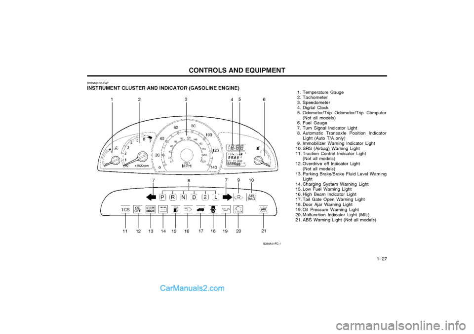
B260A01FC-EAT INSTRUMENT CLUSTER AND INDICATOR (GASOLINE ENGINE) 1. Temperature Gauge
2. Tachometer
3. Speedometer
4. Digital Clock
5. Odometer/Trip Odometer/Trip Computer
(Not all models)
6. Fuel Gauge
7. Turn Signal Indicator Light
8. Automatic Transaxle Position Indicator Light (Auto T/A only)
9. Immobilizer Warning Indicator Light
10. SRS (Airbag) Warning Light
11. Traction Control Indicator Light (Not all models)
12. Overdrive off Indicator Light (Not all models)
13. Parking Brake/Brake Fluid Level Warning Light
14. Charging System Warning Light
15. Low Fuel Warning Light
16. High Beam Indicator Light
17. Tail Gate Open Warning Light
18. Door Ajar Warning Light
19. Oil Pressure Warning Light
20. Malfunction Indicator Light (MIL)
21. ABS Warning Light (Not all models)
B260A01FC-1
1
2 3
45
6
7 8 910
11 12 13 14 15 16 17 18
1920 21
7
Page 209 of 312

CONTROLS AND EQUIPMENT
1- 28
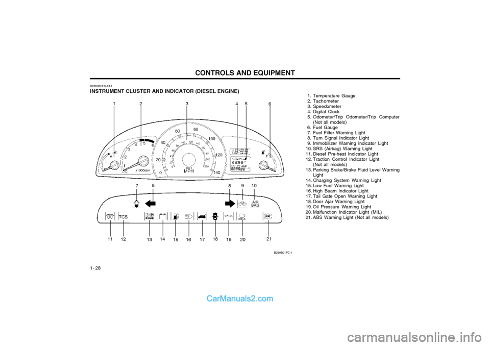
B260B01FC-EAT INSTRUMENT CLUSTER AND INDICATOR (DIESEL ENGINE) 1. Temperature Gauge
2. Tachometer
3. Speedometer
4. Digital Clock
5. Odometer/Trip Odometer/Trip Computer
(Not all models)
6. Fuel Gauge
7. Fuel Filter Warning Light
8. Turn Signal Indicator Light
9. Immobilizer Warning Indicator Light
10. SRS (Airbag) Warning Light
11. Diesel Pre-heat Indicator Light
12. Traction Control Indicator Light
(Not all models)
13. Parking Brake/Brake Fluid Level Warning Light
14. Charging System Warning Light
15. Low Fuel Warning Light
16. High Beam Indicator Light
17. Tail Gate Open Warning Light
18. Door Ajar Warning Light
19. Oil Pressure Warning Light
20. Malfunction Indicator Light (MIL)
21. ABS Warning Light (Not all models)
B260B01FC-1
1 23 4 5
6
7 8
910
8
11 12
1314
15 16 17 18
19 20 21
Page 220 of 312

1- 39
CONTROLS AND EQUIPMENTSB290A02-F CIGAR LIGHTER For the cigar lighter to work, the key must be in the "ACC" or the "ON" position.To use the cigar lighter, push the lighter all theway into its socket. When the element isheated, the lighter will pop out into the "ready"position. Do not hold the cigar lighter at the depressed position which may result in damage to thevehicle wiring or an electrical fire. If it is necessary to replace the cigarette lighter, use only a genuine Hyundai replace-ment part. CAUTION: Do not use electric accessories or equip- ment other than the Hyundai genuine partsin the socket. The front ashtray may be opened by pulling itup by its top edge. To remove the ashtray toempty or clean it, pull the cover up all the wayout. The ashtray light will only illuminate whenthe external lights are on.
B430A01FC-GAT FRONT ASHTRAY
There are three control buttons for the digital clock. Their functions are: HOUR - Push "H" to advance the hour indicat-
ed. MIN - Push "M" to advance the minute indicat-
ed.RESET - Push "R" to reset minutes to ":00" to
facilitate resetting the clock to the correct time. When this is done: Pressing "R" between 10 : 30 and 11 : 29 changes the readout to 11 : 00. Pressing "R" between 11 : 30 and 12 : 29 changes the readout to 12 : 00.
B400A01A-AAT DIGITAL CLOCK
B420A01FC-DHFC2091HFC2056-D
Page 223 of 312

CONTROLS AND EQUIPMENT
1- 42
SB330C1-E Tilting the Sunroof System The sunroof can be tilted and closed by de-
pressing the button indicated. Release the button when the sunroof reaches the up posi-tion.
NOTE: The sunroof should not be opened when
water or standing rain is on the roof panel. Driving the vehicle for a short distance willallow the water to disperse naturally atwhich point the sunroof may be opened.
2. Turn the hexagonal bolts with a socketwrench counterclockwise to remove thefront overhead console.
3. Insert the hexagonal head wrench pro- vided with the vehicle into the socket. Thiswrench can be found in the vehicle's lug-gage room or glove box.
B460D01FC-EAT
Manual Operation of Sunroof
HFC1036
If the sunroof fails to operate:
1. Remove the rectangular plastic interior light lens in the front overhead console.
HFC1037
4. Turn the wrench clockwise to open or counterclockwise to close.
CAUTION:
o Do not open the sunroof in severe cold
temperature or when it is covered with ice or snow.
o Periodically remove any dirt that may have accumulated on the guide rails.
WARNING:
o Ensure that the sunroof and guide rails are clear of obstructions before closing the sunroof and ensure that nothingmay become entrapped between thesunroof panel and the vehicle bodywhilst the sunroof is being closed.
o Do not stand up or extend any portion of your body out of the opening whilstthe vehicle is moving.
HFC2022HFC1038
Page 242 of 312

1- 61
CONTROLS AND EQUIPMENT
B870D01FC-GAT ANTENNA Roof Antenna
Your car uses a roof antenna to receive both AM and FM broadcast signals. This antenna is a removable type. To remove the antenna, turn the antenna counterclock-wise. To install the antenna, turn the antennaclockwise. CAUTION:
o Be sure to remove the antenna before washing the car in an automatic car wash or it may be damaged.
o Before entering a place with a low height clearance, be sure to adjust the roofantenna low.
o When reinstalling your antenna, it is important that it is fully tightened toensure proper reception.
HFC2100
Page 248 of 312

DRIVING YOUR HYUNDAI
2- 6 The shift points as shown above are recom-
mended for optimum fuel economy and per- formance. SC100A1-F
RECOMMENDED SHIFT POINTS
Shift
from-to
1-2 2-33-4 4-5 Recommended
mph (km/h)
15 (20)25 (40) 35 (55)45 (75)
C090A01FC-D
C090A01A-GAT
AUTOMATIC TRANSAXLE
The highly efficient Hyundai automatic transaxle has four forward speeds and onereverse speed. It has a conventional shiftpattern as shown in the illustration. At night,with the first position of the multi-functionswitch, the appropriate symbol on the shiftpattern indicator will be illuminated accordingto the range selected. CAUTION: Never shift into "R" or "P" position while the vehicle is moving. NOTE: Depress the brake pedal and push the button when shifting. Push the button when shifting.The selector lever can be shifted free- ly.
SC090D1-F To Remove the Ignition Key
1. Turn the ignition key to the "ACC" position.
2. Simultaneously push and turn the ignitionkey counterclockwise from the "ACC" posi- tion to the "LOCK" position.
3. The key can be removed in the "LOCK" position.
C070C01E
LOCK
ACC
ON
START
Page 261 of 312

IN CASE OF EMERGENCY
3-4
SD070A1-E
CHANGING A FLAT TYRE
It is of the utmost importance that care is exercised when changing road wheels. En-sure that the parking brake is set and that thegear shift lever is in reverse (P, if the vehiclehas automatic transaxle).
D060A01FC-D
D060K01FC-EAT
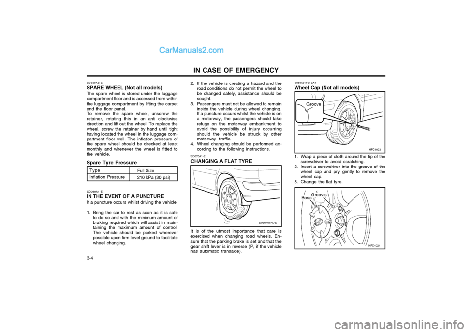
Wheel Cap (Not all models)
HFC4024
1. Wrap a piece of cloth around the tip of the
screwdriver to avoid scratching.
2. Insert a screwdriver into the groove of the wheel cap and pry gently to remove the wheel cap.
3. Change the flat tyre. HFC4023
Groove
BossGroove
SD060A1-E
IN THE EVENT OF A PUNCTURE If a puncture occurs whilst driving the vehicle:
1. Bring the car to rest as soon as it is safe to do so and with the minimum amount of braking required which will assist in main-taining the maximum amount of control.The vehicle should be parked whereverpossible upon firm level ground to facilitatewheel changing.
SD050A2-E SPARE WHEEL (Not all models) The spare wheel is stored under the luggage compartment floor and is accessed from withinthe luggage compartment by lifting the carpetand the floor panel. To remove the spare wheel, unscrew the retainer, rotating this in an anti clockwisedirection and lift out the wheel. To replace thewheel, screw the retainer by hand until tighthaving located the wheel in the luggage com-partment floor well. The inflation pressure ofthe spare wheel should be checked at leastmonthly and whenever the wheel is fitted tothe vehicle.
Spare Tyre Pressure
Type Inflation Pressure Full Size210 kPa (30 psi)
2. If the vehicle is creating a hazard and the
road conditions do not permit the wheel to be changed safely, assistance should besought.
3. Passengers must not be allowed to remain inside the vehicle during wheel changing.If a puncture occurs whilst the vehicle is ona motorway, the passengers should takerefuge on the motorway embankment toavoid the possibility of injury occurringshould the vehicle be struck by othermotorway traffic.
4. Wheel changing should be performed ac- cording to the following instructions.