INFINITI M35 2006 Factory Service Manual
M35 2006
INFINITI
INFINITI
https://www.carmanualsonline.info/img/42/57023/w960_57023-0.png
INFINITI M35 2006 Factory Service Manual
Trending: dimensions, start stop button, Crankshaft Position Sensor, fuel pump, navigation system, oil change, maintenance schedule
Page 1481 of 5621
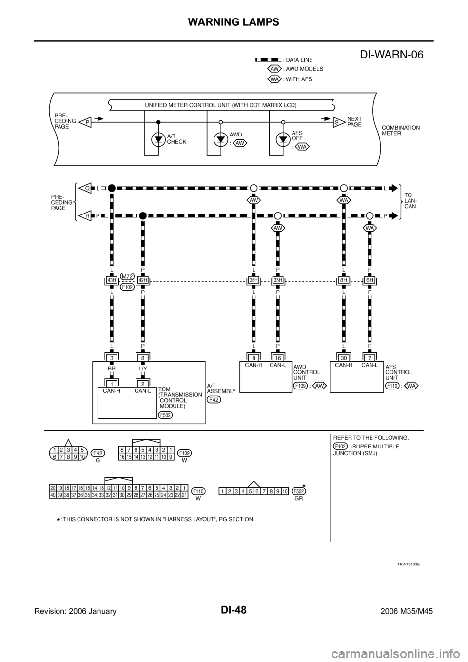
DI-48
WARNING LAMPS
Revision: 2006 January2006 M35/M45
TKWT3432E
Page 1482 of 5621
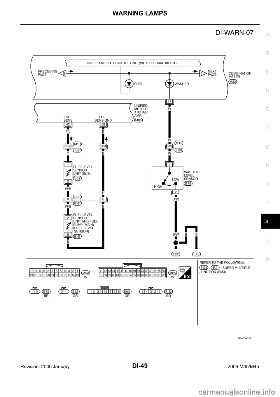
WARNING LAMPS
DI-49
C
D
E
F
G
H
I
J
L
MA
B
DI
Revision: 2006 January2006 M35/M45
TKWT3433E
Page 1483 of 5621
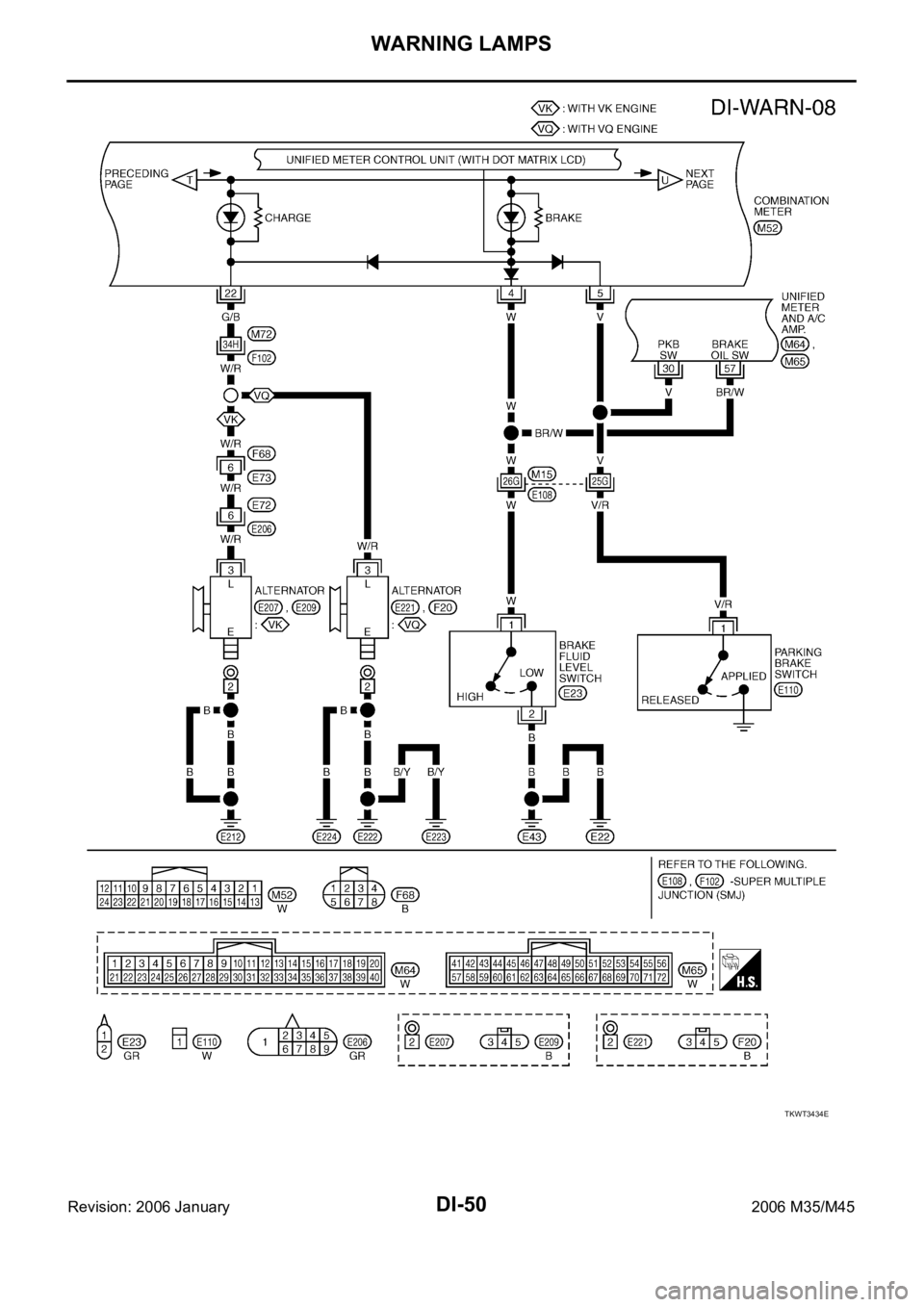
DI-50
WARNING LAMPS
Revision: 2006 January2006 M35/M45
TKWT3434E
Page 1484 of 5621
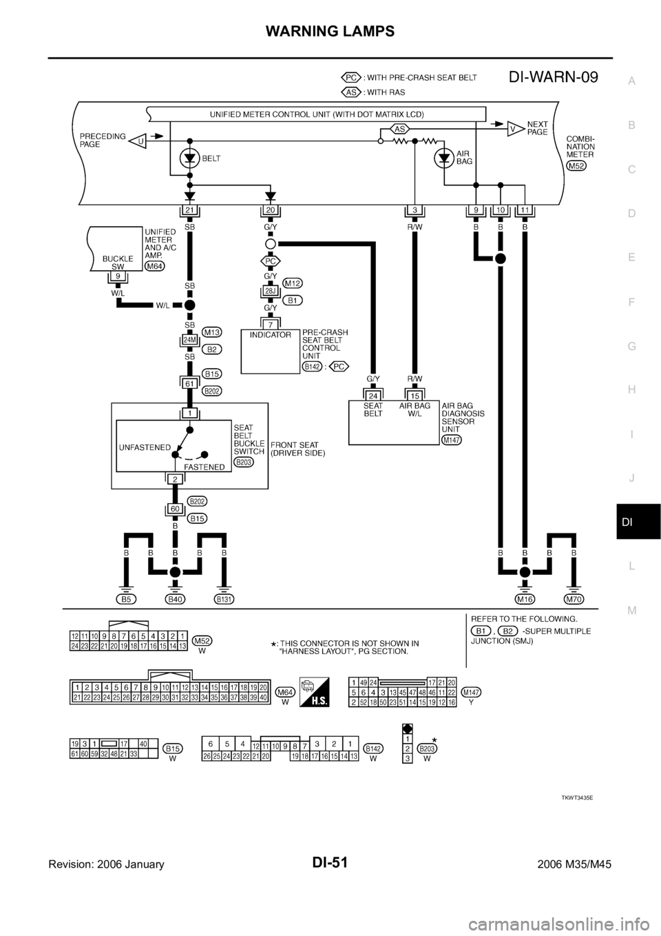
WARNING LAMPS
DI-51
C
D
E
F
G
H
I
J
L
MA
B
DI
Revision: 2006 January2006 M35/M45
TKWT3435E
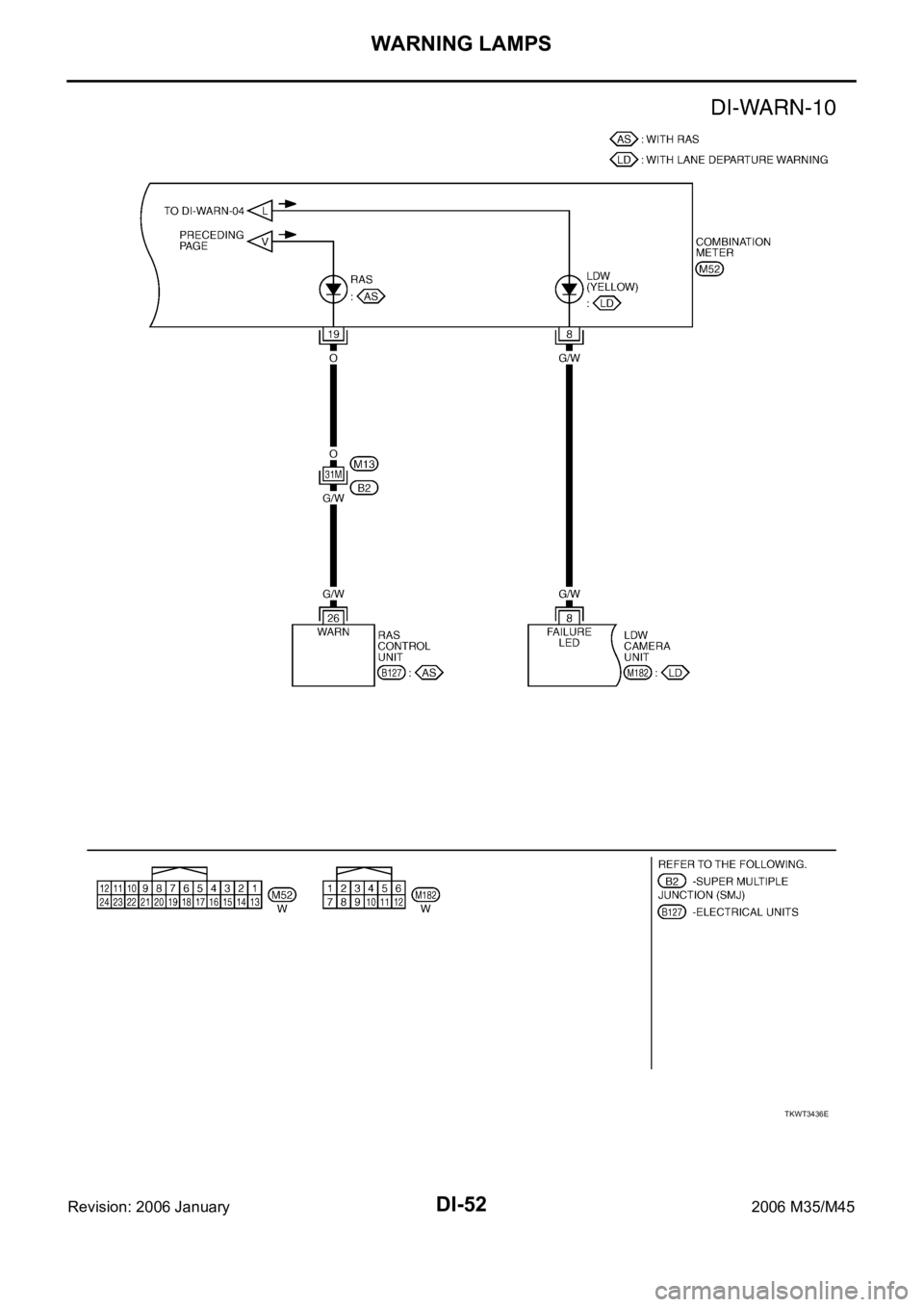
Page 1485 of 5621
DI-52
WARNING LAMPS
Revision: 2006 January2006 M35/M45
TKWT3436E
Page 1486 of 5621

WARNING LAMPS
DI-53
C
D
E
F
G
H
I
J
L
MA
B
DI
Revision: 2006 January2006 M35/M45
Oil Pressure Warning Lamp Stays Off (Ignition Switch ON)NKS003US
1. CHECK OPERATION OF OIL PRESSURE WARNING LAMP
Activate IPDM E/R auto active test. Refer to PG-24, "
Auto Active Test" .
Does oil pressure warning lamp is blinking?
YES >> GO TO 2.
NO >> GO TO 4.
2. CHECK OIL PRESSURE SWITCH CIRCUIT
1. Turn ignition switch OFF.
2. Disconnect IPDM E/R connector and oil pressure switch con-
nector.
3. Check continuity between IPDM E/R harness connector (A) and
oil pressure switch harness connector (B).
OK or NG
OK >> GO TO 3.
NG >> Repair harness or connector.
3. CHECK OIL PRESSURE SWITCH
Check oil pressure switch. Refer to DI-55, "
OIL PRESSURE SWITCH" .
OK or NG
OK >> Replace IPDM E/R. Refer to PG-31, "Removal and Installation of IPDM E/R" .
NG >> Replace oil pressure switch.
4. CHECK UNIFIED METER AND A/C AMP. (CONSULT-II)
Perform self-diagnosis of unified meter and A/C amp. Refer to DI-31, "
CONSULT-II Function (METER A/C
AMP)" .
Self
-diagnostic results content
No malfunction detected>> GO TO 5.
Malfunction detected>> Check applicable parts, and repair or replace corresponding parts.
5. CHECK UNIFIED METER AND A/C AMP. INPUT SIGNAL
1. Select “METER A/C AMP” on CONSULT-II.
2. Operate ignition switch with “OIL W/L” of “DATA MONITOR” and
check operation status.
OK or NG
OK >> Replace combination meter.
NG >> GO TO 6.
AB
Continuity
Connector Terminal Connector Terminal
E9 52 F21 1 Yes
PKIB7657E
“OIL W/L”
When ignition switch is in ON
position (Engine stopped): ON
When engine running : OFF
PKIA2064E
Page 1487 of 5621

DI-54
WARNING LAMPS
Revision: 2006 January2006 M35/M45
6. CHECK BCM INPUT SIGNAL
1. Select “SIGNAL BUFFER” of “BCM” on CONSULT-II.
2. Operate ignition switch with “OIL PRESS SW” of “DATA MONI-
TOR” and check operate status.
OK or NG
OK >> Replace BCM. Refer to BCS-17, "Removal and Installa-
tion of BCM" .
NG >> Replace IPDM E/R. Refer to PG-31, "
Removal and Installation of IPDM E/R" .
Oil Pressure Warning Lamp Does Not Turn Off (Oil Pressure Is Normal)NKS003UT
NOTE:
For oil pressure inspection, refer to LU-8, "
OIL PRESSURE CHECK" (VQ35DE) or LU-26, "OIL PRESSURE
CHECK" (VK45DE).
1. CHECK OPERATION OF OIL PRESSURE WARNING LAMP
Activate IPDM E/R auto active test. Refer to PG-24, "
Auto Active Test" .
Does oil pressure warning lamp is blinking?
YES >> GO TO 2.
NO >> GO TO 5.
2. CHECK IPDM E/R OUTPUT SIGNAL
1. Turn ignition switch OFF.
2. Disconnect oil pressure switch connector.
3. Turn ignition switch ON.
4. Check voltage between oil pressure switch harness connector
and ground.
OK or NG
OK >> GO TO 3.
NG >> GO TO 4.
3. CHECK OIL PRESSURE SWITCH
1. Turn ignition switch OFF.
2. Check oil pressure switch. Refer to DI-55, "
OIL PRESSURE SWITCH" .
OK or NG
OK >> Replace IPDM E/R. Refer to PG-31, "Removal and Installation of IPDM E/R" .
NG >> Replace oil pressure switch.“OIL PRESS SW”
When ignition switch is in ON
position (Engine stopped): ON
When engine running : OFF
SKIA8709E
Terminals
Voltage (Approx.) (+)
(–)
Oil pressure switch
connectorTe r m i n a l
F21 1 Ground 12 V
PKIB7658E
Page 1488 of 5621

WARNING LAMPS
DI-55
C
D
E
F
G
H
I
J
L
MA
B
DI
Revision: 2006 January2006 M35/M45
4. CHECK OIL PRESSURE SWITCH CIRCUIT
1. Turn ignition switch OFF.
2. Disconnect IPDM E/R connector.
3. Check continuity between IPDM E/R harness connector and
ground.
OK or NG
OK >> Replace IPDM E/R. Refer to PG-31, "Removal and
Installation of IPDM E/R" .
NG >> Repair harness or connector.
5. CHECK IPDM E/R (CONSULT-II)
Perform self-diagnosis of IPDM E/R. Refer to PG-20, "
CONSULT-II Function (IPDM E/R)" .
Self
-diagnostic results content
No malfunction detected>> Replace combination meter.
Malfunction detected>> Check applicable parts, and repair or replace corresponding parts.
Electrical Component InspectionNKS003UU
OIL PRESSURE SWITCH
Check continuity between oil pressure switch and ground.
IPDM E/R connector Terminal
GroundContinuity
E9 52 No
PKIB7659E
Condition
Oil pressure [kPa (kg/cm2 , psi)]Continuity
Engine stopped Less than 29 (0.3, 4) Yes
Engine running More than 29 (0.3, 4) No
ELF0044D
Page 1489 of 5621

DI-56
A/T INDICATOR
Revision: 2006 January2006 M35/M45
A/T INDICATORPFP:24814
System DescriptionNKS003UV
A/T position is displayed in the dot matrix LCD in the combination meter.
MANUAL MODE
Unified meter and A/C amp. inputs manual mode signal and shift-up/down signal from A/T device (manual
mode switch), and transmits the signals to TCM with CAN communication.
TCM processes manual mode signal and shift-up/down signal, and transmits manual mode indicator sig-
nal and A/T position indicator signal to unified meter and A/C amp. with CAN communication.
Unified meter and A/C amp. transmits manual mode indicator signal and A/T position indicator signal to
combination meter with the communication line.
Combination meter indicates A/T gear position and manual mode indicator, when receiving manual mode
indicator signal and A/T position indicator signal.
NOT MANUAL MODE
Unified meter and A/C amp. inputs not manual mode signal from A/T device (manual mode switch), and
transmits the signals to TCM with CAN communication.
TCM transmits A/T position indicator signal to unified meter and A/C amp. with CAN communication.
Unified meter and A/C amp. transmits A/T position indicator signal to combination meter with the commu-
nication line.
Combination meter indicates A/T shift position when receiving A/T position indicator signal.
PKIB7660E
Page 1490 of 5621
A/T INDICATOR
DI-57
C
D
E
F
G
H
I
J
L
MA
B
DI
Revision: 2006 January2006 M35/M45
Wiring Diagram — AT/IND —NKS003UW
TKWT3438E
Trending: remove seats, ECO mode, power steering, washer fluid, headlights, sport mode, warning light
