INFINITI M35 2006 Factory Service Manual
Manufacturer: INFINITI, Model Year: 2006, Model line: M35, Model: INFINITI M35 2006Pages: 5621, PDF Size: 65.56 MB
Page 461 of 5621

ATC-14
PRECAUTIONS
Revision: 2006 January2006 M35/M45
SERVICE HOSES
Be certain that the service hoses display the markings described
(colored hose with black stripe). All hoses must include positive shut-
off devices (either manual or automatic) near the end of the hoses
opposite to the manifold gauge.
SERVICE COUPLERS
Never attempt to connect HFC-134a (R-134a) service couplers to a
CFC-12 (R-12) A/C system. The HFC-134a (R-134a) couplers will
not properly connect to the CFC-12 (R-12) system. However, if an
improper connection is attempted, discharging and contamination
may occur.
REFRIGERANT WEIGHT SCALE
Verify that no refrigerant other than HFC-134a (R-134a) and speci-
fied lubricants have been used with the scale. If the scale controls
refrigerant flow electronically, the hose fitting must be 1/2
-16
ACME.
CHARGING CYLINDER
Using a charging cylinder is not recommended. Refrigerant may be vented into air from cylinder’s top valve
when filling the cylinder with refrigerant. Also, the accuracy of the cylinder is generally less than that of an
electrical scale or of quality recycle/recharge equipment.
RHA272D
Shut-off valve rotation A/C service valve
Clockwise Open
Counterclockwise Close
RHA273D
RHA274D
Page 462 of 5621

PRECAUTIONS
ATC-15
C
D
E
F
G
H
I
K
L
MA
B
AT C
Revision: 2006 January2006 M35/M45
Precautions for Leak Detection DyeNJS000FV
The A/C system contains a fluorescent leak detection dye used for locating refrigerant leaks. An ultraviolet
(UV) lamp is required to illuminate the dye when inspecting for leaks.
Always wear fluorescence enhancing UV safety goggles to protect your eyes and enhance the visibility of
the fluorescent dye.
The fluorescent dye leak detector is not a replacement for an electrical leak detector. The fluorescent dye
leak detector should be used in conjunction with an electrical leak detector (SST: J-41995) to pin-point
refrigerant leaks.
For the purpose of safety and customer’s satisfaction, read and follow all manufacture’s operating instruc-
tions and precautions prior to performing the work.
A compressor shaft seal should not necessarily be repaired because of dye seepage. The compressor
shaft seal should only be repaired after confirming the leak with an electrical leak detector (SST: J-41995).
Always remove any remaining dye from the leak area after repairs are completed to avoid a misdiagnosis
during a future service.
Never allow dye to come into contact with painted body panels or interior components. If dye is spilled,
clean immediately with the approved dye cleaner. Fluorescent dye left on a surface for an extended period
of time cannot be removed.
Never spray the fluorescent dye cleaning agent on hot surfaces (engine exhaust manifold, etc.).
Never use more than one refrigerant dye bottle (1/4 ounce /7.4 cc) per A/C system.
Leak detection dyes for HFC-134a (R-134a) and CFC-12 (R-12) A/C systems are different. Never use
HFC-134a (R-134a) leak detection dye in CFC-12 (R-12) A/C system, or CFC-12 (R-12) leak detection
dye in HFC-134a (R-134a) A/C system, or A/C system damage may result.
The fluorescent properties of the dye will remain for three years or a little over unless a compressor mal-
function occurs.
IDENTIFICATION
NOTE:
Vehicles with factory installed fluorescent dye have a green label.
Vehicles without factory installed fluorescent dye have a blue label.
IDENTIFICATION LABEL FOR VEHICLE
Vehicles with factory installed fluorescent dye have the identification label on the front side of hood.
Page 463 of 5621

ATC-16
PREPARATION
Revision: 2006 January2006 M35/M45
PREPARATIONPFP:00002
Special Service ToolsNJS000FW
The actual shapes of Kent-Moore tools may differ from those of special service tools illustrated here.
Tool number
(Kent-Moore No.)
Tool nameDescription
9253089908
(for high-pressure pipe 1)
(-)
9253089912
(for high-pressure flexible hose)
(-)
9253089916
(for low-pressure pipe 1 and
low-pressure flexible hose)
(-)
Disconnector tool set
(J-45815)Disconnect one-touch joint connection
SJIA1274E
Page 464 of 5621

PREPARATION
ATC-17
C
D
E
F
G
H
I
K
L
MA
B
AT C
Revision: 2006 January2006 M35/M45
HFC-134a (R-134a) Service Tools and EquipmentNJS000FX
Never mix HFC-134a (R-134a) refrigerant and/or its specified lubricant with CFC-12 (R-12) refrigerant and/or
its lubricant.
Separate and non-interchangeable service equipment must be used for handling each type of refrigerant/lubri-
cant.
Refrigerant container fittings, service hose fittings and service equipment fittings (equipment which handles
refrigerant and/or lubricant) are different between CFC-12 (R-12) and HFC-134a (R-134a). This is to avoid
mixed use of the refrigerants/lubricant.
Never use adapters that convert one size fitting to another: refrigerant/lubricant contamination occurs and
compressor malfunction may result.
Tool number
(Kent-Moore No.)
Tool nameDescription
HFC-134a (R-134a) refrigerantContainer color: Light blue
Container marking: HFC-134a (R-
134a)
Fitting size: Thread size
Large container 1/2 -16 ACME
Nissan A/C System Oil Type S
(DH-PS)Type: Polyalkylene glycol oil (PAG),
type S (DH-PS)
Application: HFC-134a (R-134a)
swash plate compressors (Nissan
only)
Capacity: 40 m (1.4 US fl oz., 1.4
Imp fl oz.)
(ACR2005-NI)
ACR5 A/C Service CenterFunction: Refrigerant recovery,
recycling and recharging
(J-41995)
Electrical A/C leak detectorPower supply:
DC 12 V (Battery terminal)
S-NT196
S-NT197
WJIA0293E
AHA281A
Page 465 of 5621

ATC-18
PREPARATION
Revision: 2006 January2006 M35/M45
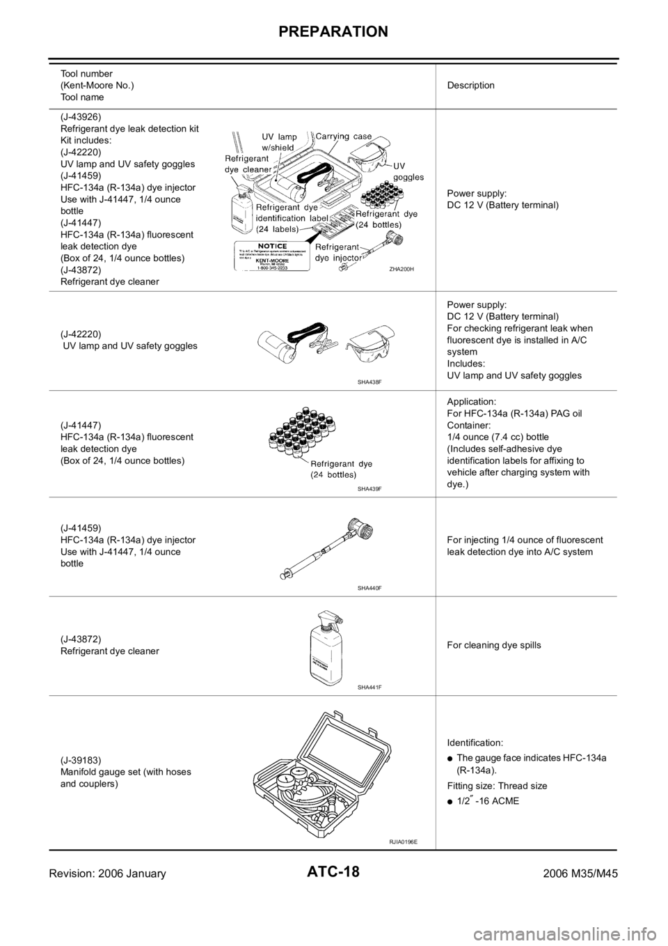
(J-43926)
Refrigerant dye leak detection kit
Kit includes:
(J-42220)
UV lamp and UV safety goggles
(J-41459)
HFC-134a (R-134a) dye injector
Use with J-41447, 1/4 ounce
bottle
(J-41447)
HFC-134a (R-134a) fluorescent
leak detection dye
(Box of 24, 1/4 ounce bottles)
(J-43872)
Refrigerant dye cleanerPower supply:
DC 12 V (Battery terminal)
(J-42220)
UV lamp and UV safety gogglesPower supply:
DC 12 V (Battery terminal)
For checking refrigerant leak when
fluorescent dye is installed in A/C
system
Includes:
UV lamp and UV safety goggles
(J-41447)
HFC-134a (R-134a) fluorescent
leak detection dye
(Box of 24, 1/4 ounce bottles)Application:
For HFC-134a (R-134a) PAG oil
Container:
1/4 ounce (7.4 cc) bottle
(Includes self-adhesive dye
identification labels for affixing to
vehicle after charging system with
dye.)
(J-41459)
HFC-134a (R-134a) dye injector
Use with J-41447, 1/4 ounce
bottleFor injecting 1/4 ounce of fluorescent
leak detection dye into A/C system
(J-43872)
Refrigerant dye cleanerFor cleaning dye spills
(J-39183)
Manifold gauge set (with hoses
and couplers)Identification:
The gauge face indicates HFC-134a
(R-134a).
Fitting size: Thread size
1/2 -16 ACME Tool number
(Kent-Moore No.)
Tool nameDescription
ZHA200H
SHA438F
SHA439F
SHA440F
SHA441F
RJIA0196E
Page 466 of 5621

PREPARATION
ATC-19
C
D
E
F
G
H
I
K
L
MA
B
AT C
Revision: 2006 January2006 M35/M45
Commercial Service ToolsNJS000FY
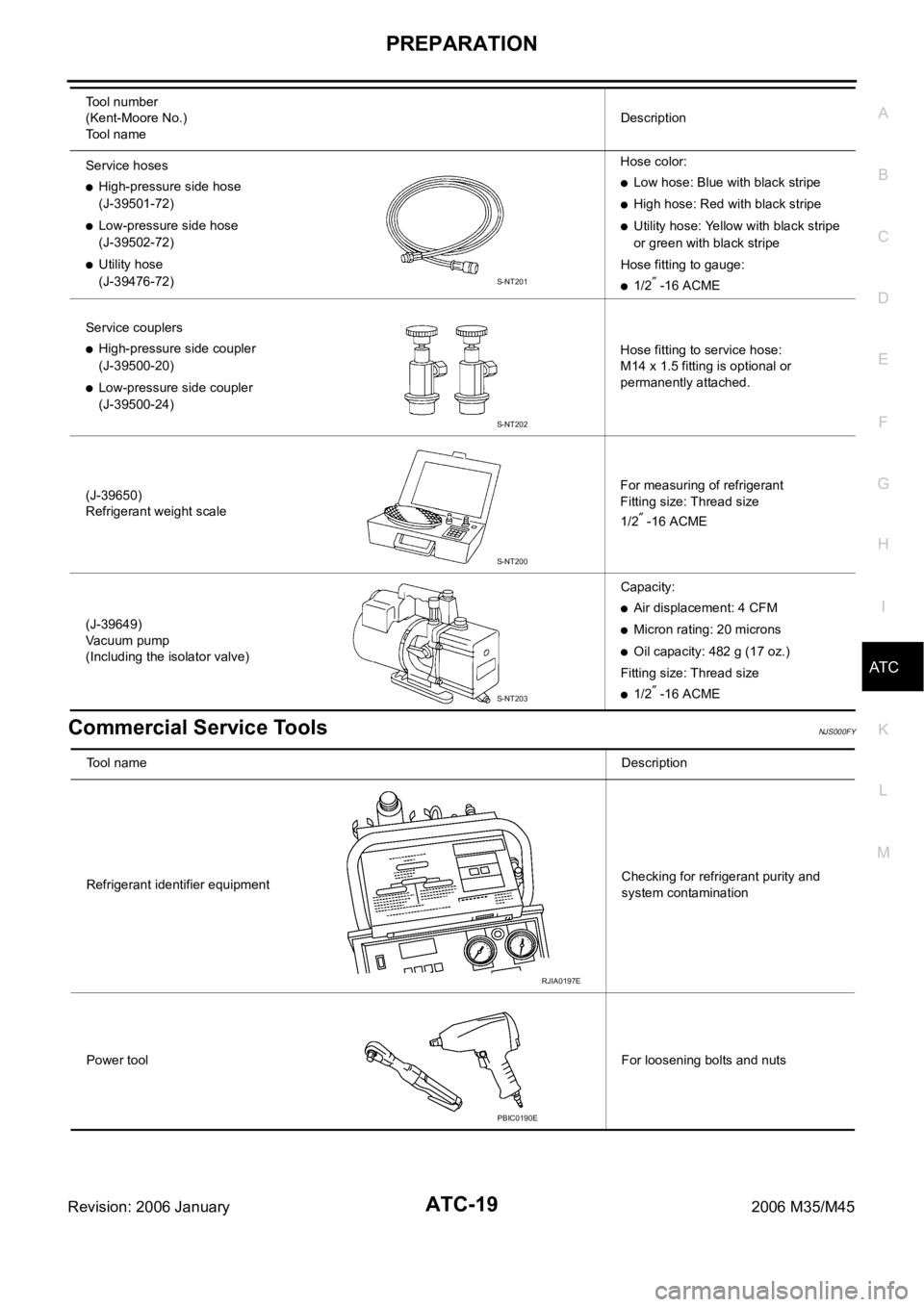
Service hoses
High-pressure side hose
(J-39501-72)
Low-pressure side hose
(J-39502-72)
Utility hose
(J-39476-72)Hose color:
Low hose: Blue with black stripe
High hose: Red with black stripe
Utility hose: Yellow with black stripe
or green with black stripe
Hose fitting to gauge:
1/2 -16 ACME
Service couplers
High-pressure side coupler
(J-39500-20)
Low-pressure side coupler
(J-39500-24)Hose fitting to service hose:
M14 x 1.5 fitting is optional or
permanently attached.
(J-39650)
Refrigerant weight scaleFor measuring of refrigerant
Fitting size: Thread size
1/2
-16 ACME
(J-39649)
Vacuum pump
(Including the isolator valve)Capacity:
Air displacement: 4 CFM
Micron rating: 20 microns
Oil capacity: 482 g (17 oz.)
Fitting size: Thread size
1/2 -16 ACME Tool number
(Kent-Moore No.)
Tool nameDescription
S-NT201
S-NT202
S-NT200
S-NT203
Tool nameDescription
Refrigerant identifier equipmentChecking for refrigerant purity and
system contamination
Power toolFor loosening bolts and nuts
RJIA0197E
PBIC0190E
Page 467 of 5621

ATC-20
REFRIGERATION SYSTEM
Revision: 2006 January2006 M35/M45
REFRIGERATION SYSTEMPFP:KA990
Refrigerant CycleNJS000FZ
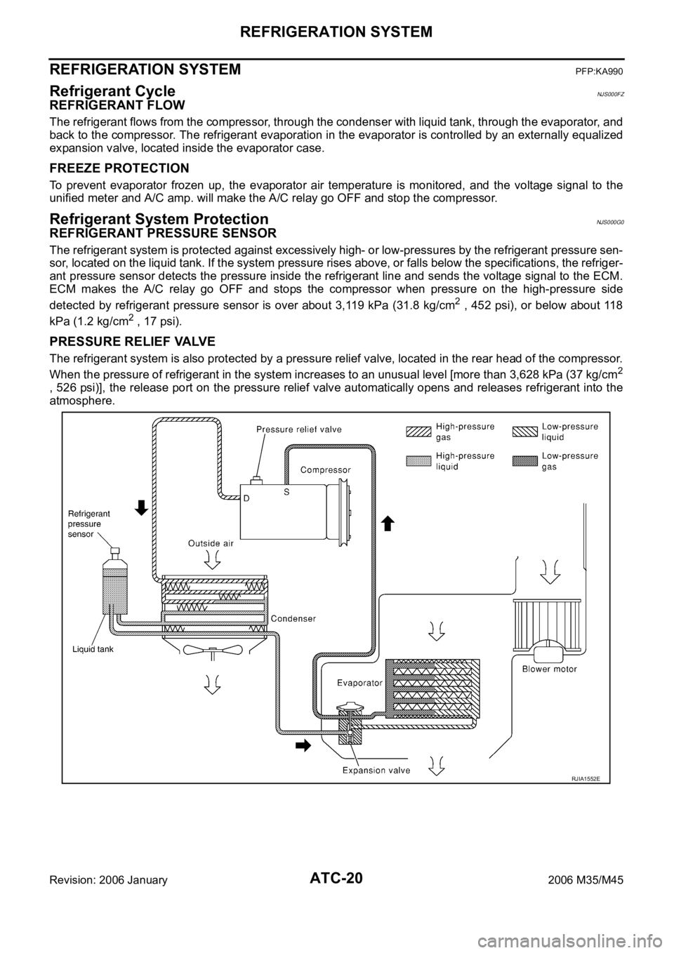
REFRIGERANT FLOW
The refrigerant flows from the compressor, through the condenser with liquid tank, through the evaporator, and
back to the compressor. The refrigerant evaporation in the evaporator is controlled by an externally equalized
expansion valve, located inside the evaporator case.
FREEZE PROTECTION
To prevent evaporator frozen up, the evaporator air temperature is monitored, and the voltage signal to the
unified meter and A/C amp. will make the A/C relay go OFF and stop the compressor.
Refrigerant System ProtectionNJS000G0
REFRIGERANT PRESSURE SENSOR
The refrigerant system is protected against excessively high- or low-pressures by the refrigerant pressure sen-
sor, located on the liquid tank. If the system pressure rises above, or falls below the specifications, the refriger-
ant pressure sensor detects the pressure inside the refrigerant line and sends the voltage signal to the ECM.
ECM makes the A/C relay go OFF and stops the compressor when pressure on the high-pressure side
detected by refrigerant pressure sensor is over about 3,119 kPa (31.8 kg/cm
2 , 452 psi), or below about 118
kPa (1.2 kg/cm
2 , 17 psi).
PRESSURE RELIEF VALVE
The refrigerant system is also protected by a pressure relief valve, located in the rear head of the compressor.
When the pressure of refrigerant in the system increases to an unusual level [more than 3,628 kPa (37 kg/cm
2
, 526 psi)], the release port on the pressure relief valve automatically opens and releases refrigerant into the
atmosphere.
RJIA1552E
Page 468 of 5621

REFRIGERATION SYSTEM
ATC-21
C
D
E
F
G
H
I
K
L
MA
B
AT C
Revision: 2006 January2006 M35/M45
Variable Displacement CompressorNJS000G1
GENERAL INFORMATION
1. The variable compressor provides refrigerant control under varying conditions. During cold winters, it may
not produce high refrigerant pressure discharge (compared to previous units) when used with air condi-
tioning systems.
2. For air conditioning systems with the compressor, the clutch remains engaged unless: the system main
switch, fan switch or ignition switch is turned OFF. When ambient (outside) temperatures are low or when
the amount of refrigerant is insufficient, the clutch is disengaged to protect the compressor.
Page 469 of 5621

ATC-22
REFRIGERATION SYSTEM
Revision: 2006 January2006 M35/M45
DESCRIPTION
General
The variable compressor is a swash plate type that changes piston stroke in response to the required cooling
capacity.
The tilt of the swash plate allows the piston’s stroke to change so that refrigerant discharge continuously
change from approx. 0 to 171 cm
3 (0 to 10.4 cu in).
RJIA4209E
Page 470 of 5621

REFRIGERATION SYSTEM
ATC-23
C
D
E
F
G
H
I
K
L
MA
B
AT C
Revision: 2006 January2006 M35/M45
Operation
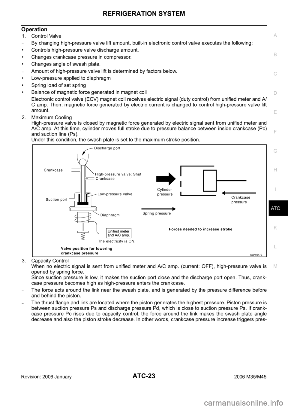
1. Control Valve
–By changing high-pressure valve lift amount, built-in electronic control valve executes the following:
• Controls high-pressure valve discharge amount.
• Changes crankcase pressure in compressor.
• Changes angle of swash plate.
–Amount of high-pressure valve lift is determined by factors below.
• Low-pressure applied to diaphragm
• Spring load of set spring
• Balance of magnetic force generated in magnet coil
–Electronic control valve (ECV) magnet coil receives electric signal (duty control) from unified meter and A/
C amp. Then, magnetic force generated by electric current is changed to control high-pressure valve lift
amount.
2. Maximum Cooling
High-pressure valve is closed by magnetic force generated by electric signal sent from unified meter and
A/C amp. At this time, cylinder moves full stroke due to pressure balance between inside crankcase (Pc)
and suction line (Ps).
Under this condition, the swash plate is set to the maximum stroke position.
3. Capacity Control
When no electric signal is sent from unified meter and A/C amp. (current: OFF), high-pressure valve is
opened by spring force.
Since suction pressure is low, it makes the suction port close and the discharge port open. Thus, crank-
case pressure becomes high as high-pressure enters the crankcase.
–The force acts around the link near the swash plate, and is generated by the pressure difference before
and behind the piston.
–The thrust flange and link are located where the piston generates the highest pressure. Piston pressure is
between suction pressure Ps and discharge pressure Pd, which is close to suction pressure Ps. If crank-
case pressure Pc rises due to capacity control, the force around the link makes the swash plate angle
decrease and also the piston stroke decrease. In other words, crankcase pressure increase triggers pres-
SJIA0547E