service INFINITI QX4 2001 Factory Service Manual
[x] Cancel search | Manufacturer: INFINITI, Model Year: 2001, Model line: QX4, Model: INFINITI QX4 2001Pages: 2395, PDF Size: 43.2 MB
Page 1189 of 2395

Supplemental Restraint System (SRS) ªAIR
BAGº and ªSEAT BELT PRE-TENSIONERº
NBEL0001The Supplemental Restraint System such as ªAIR BAGº and ªSEAT BELT PRE-TENSIONERº used along with
a seat belt, helps to reduce the risk or severity of injury to the driver and front passenger for certain types of
collision. The SRS system composition which is available to INFINITI QX4 is as follows:
IFor a frontal collision
The Supplemental Restraint System consists of driver air bag module (located in the center of the steer-
ing wheel), front passenger air bag module (located on the instrument panel on passenger side), seat belt
pre-tensioners, a diagnosis sensor unit, warning lamp, wiring harness and spiral cable.
IFor a side collision
The Supplemental Restraint System consists of side air bag module (located in the outer side of front seat),
satellite sensor, diagnosis sensor unit (one of components of air bags for a frontal collision), wiring harness,
warning lamp (one of components of air bags for a frontal collision).
Information necessary to service the system safely is included in theRS sectionof this Service Manual.
WARNING:
ITo avoid rendering the SRS inoperative, which could increase the risk of personal injury or death
in the event of a collision which would result in air bag inflation, all maintenance must be performed
by an authorized INFINITI dealer.
IImproper maintenance, including incorrect removal and installation of the SRS, can lead to per-
sonal injury caused by unintentional activation of the system. For removal of Spiral Cable and Air
Bag Module, see the RS section.
IDo not use electrical test equipment on any circuit related to the SRS unless instructed to in this
Service Manual. Spiral cable and wiring harnesses covered with yellow insulation tape either just
before the harness connectors or for the complete harness are related to the SRS.
Wiring Diagrams and Trouble DiagnosisNBEL0002When you read wiring diagrams, refer to the following:
IGI-11, ªHOW TO READ WIRING DIAGRAMSº
IEL-9, ªPOWER SUPPLY ROUTINGº for power distribution circuit
When you perform trouble diagnosis, refer to the following:
IGI-35, ªHOW TO FOLLOW TEST GROUPS IN TROUBLE DIAGNOSESº
IGI-24, ªHOW TO PERFORM EFFICIENT DIAGNOSIS FOR AN ELECTRICAL INCIDENTº
Check for any Service bulletins before servicing the vehicle.
PRECAUTIONS
Supplemental Restraint System (SRS) ªAIR BAGº and ªSEAT BELT PRE-TENSIONERº
EL-4
Page 1225 of 2395

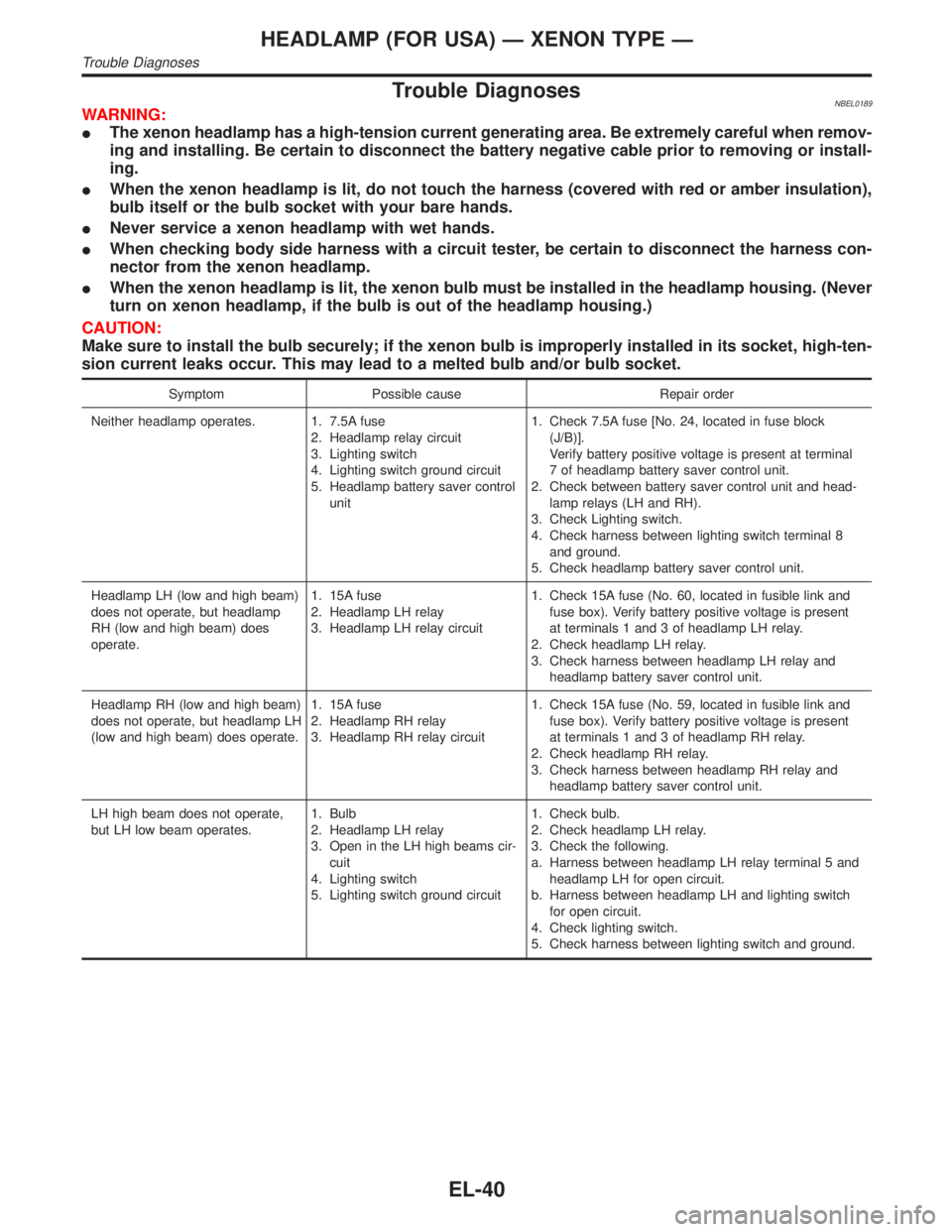
Trouble DiagnosesNBEL0189WARNING:
IThe xenon headlamp has a high-tension current generating area. Be extremely careful when remov-
ing and installing. Be certain to disconnect the battery negative cable prior to removing or install-
ing.
IWhen the xenon headlamp is lit, do not touch the harness (covered with red or amber insulation),
bulb itself or the bulb socket with your bare hands.
INever service a xenon headlamp with wet hands.
IWhen checking body side harness with a circuit tester, be certain to disconnect the harness con-
nector from the xenon headlamp.
IWhen the xenon headlamp is lit, the xenon bulb must be installed in the headlamp housing. (Never
turn on xenon headlamp, if the bulb is out of the headlamp housing.)
CAUTION:
Make sure to install the bulb securely; if the xenon bulb is improperly installed in its socket, high-ten-
sion current leaks occur. This may lead to a melted bulb and/or bulb socket.
Symptom Possible cause Repair order
Neither headlamp operates. 1. 7.5A fuse
2. Headlamp relay circuit
3. Lighting switch
4. Lighting switch ground circuit
5. Headlamp battery saver control
unit1. Check 7.5A fuse [No. 24, located in fuse block
(J/B)].
Verify battery positive voltage is present at terminal
7 of headlamp battery saver control unit.
2. Check between battery saver control unit and head-
lamp relays (LH and RH).
3. Check Lighting switch.
4. Check harness between lighting switch terminal 8
and ground.
5. Check headlamp battery saver control unit.
Headlamp LH (low and high beam)
does not operate, but headlamp
RH (low and high beam) does
operate.1. 15A fuse
2. Headlamp LH relay
3. Headlamp LH relay circuit1. Check 15A fuse (No. 60, located in fusible link and
fuse box). Verify battery positive voltage is present
at terminals 1 and 3 of headlamp LH relay.
2. Check headlamp LH relay.
3. Check harness between headlamp LH relay and
headlamp battery saver control unit.
Headlamp RH (low and high beam)
does not operate, but headlamp LH
(low and high beam) does operate.1. 15A fuse
2. Headlamp RH relay
3. Headlamp RH relay circuit1. Check 15A fuse (No. 59, located in fusible link and
fuse box). Verify battery positive voltage is present
at terminals 1 and 3 of headlamp RH relay.
2. Check headlamp RH relay.
3. Check harness between headlamp RH relay and
headlamp battery saver control unit.
LH high beam does not operate,
but LH low beam operates.1. Bulb
2. Headlamp LH relay
3. Open in the LH high beams cir-
cuit
4. Lighting switch
5. Lighting switch ground circuit1. Check bulb.
2. Check headlamp LH relay.
3. Check the following.
a. Harness between headlamp LH relay terminal 5 and
headlamp LH for open circuit.
b. Harness between headlamp LH and lighting switch
for open circuit.
4. Check lighting switch.
5. Check harness between lighting switch and ground.
HEADLAMP (FOR USA) Ð XENON TYPE Ð
Trouble Diagnoses
EL-40
Page 1228 of 2395

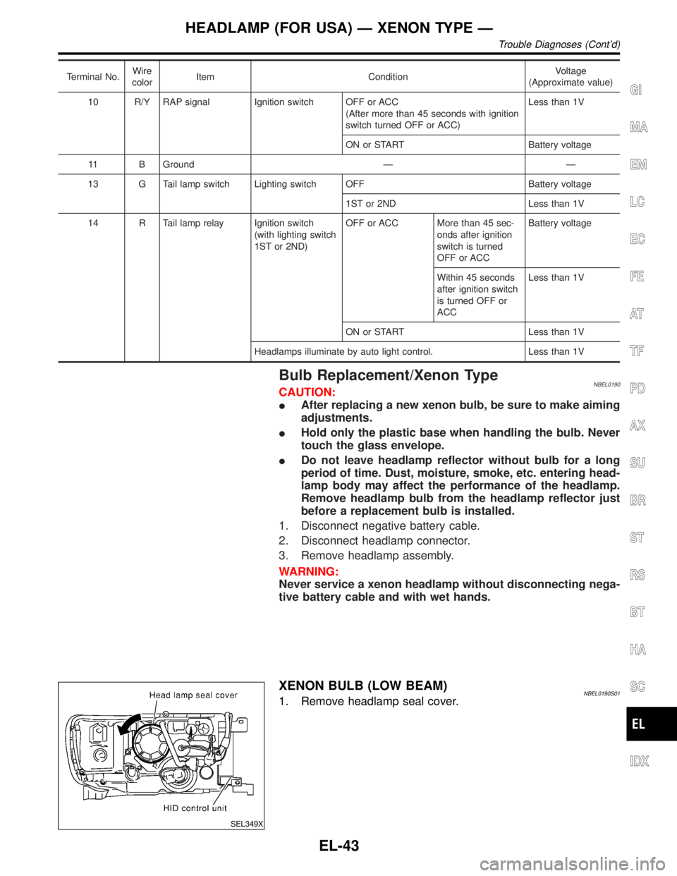
Terminal No.Wire
colorItem ConditionVoltage
(Approximate value)
10 R/Y RAP signal Ignition switch OFF or ACC
(After more than 45 seconds with ignition
switch turned OFF or ACC)Less than 1V
ON or START Battery voltage
11 B Ground Ð Ð
13 G Tail lamp switch Lighting switch OFF Battery voltage
1ST or 2ND Less than 1V
14 R Tail lamp relay Ignition switch
(with lighting switch
1ST or 2ND)OFF or ACC More than 45 sec-
onds after ignition
switch is turned
OFF or ACCBattery voltage
Within 45 seconds
after ignition switch
is turned OFF or
ACCLess than 1V
ON or START Less than 1V
Headlamps illuminate by auto light control. Less than 1V
Bulb Replacement/Xenon TypeNBEL0190CAUTION:
IAfter replacing a new xenon bulb, be sure to make aiming
adjustments.
IHold only the plastic base when handling the bulb. Never
touch the glass envelope.
IDo not leave headlamp reflector without bulb for a long
period of time. Dust, moisture, smoke, etc. entering head-
lamp body may affect the performance of the headlamp.
Remove headlamp bulb from the headlamp reflector just
before a replacement bulb is installed.
1. Disconnect negative battery cable.
2. Disconnect headlamp connector.
3. Remove headlamp assembly.
WARNING:
Never service a xenon headlamp without disconnecting nega-
tive battery cable and with wet hands.
SEL349X
XENON BULB (LOW BEAM)NBEL0190S011. Remove headlamp seal cover.
GI
MA
EM
LC
EC
FE
AT
TF
PD
AX
SU
BR
ST
RS
BT
HA
SC
IDX
HEADLAMP (FOR USA) Ð XENON TYPE Ð
Trouble Diagnoses (Cont'd)
EL-43
Page 1462 of 2395

Trouble DiagnosesNBEL0115SYMPTOM CHARTNBEL0115S01NOTE:
IAlways check remote controller battery before replacing
remote controller.
IThe panic alarm operation of multi-remote control system does
not activate with the ignition key inserted in the ignition key
cylinder.
Symptom Diagnoses/service procedureReference
page
(EL- )
All function of multi-remote control system do not
operate.1. Remote controller battery check 278
2. Power supply and ground circuit for control unit check 279
3. Replace romote controller. Refer to ID Code Entry Procedure. 291
The new ID of remote controller cannot be
entered.1. Remote controller battery check 278
2. Key switch (insert) check 282
3. Door switch check 281
4. Door lock/unlock switch LH check 283
5. Power supply and ground circuit for control unit check 279
6. Replace romote controller. Refer to ID Code Entry Procedure. 291
Door lock or unlock does not function.
(If the power door lock system does not operate
manually, check power door lock system. Refer to
EL-261.)1. Replace remote controller. Refer to ID Code Entry Procedure. 291
Hazard and horn reminder does not activate prop-
erly when pressing lock or unlock button of remote
controller.1. Harzard reminder check 285
2. Horn reminder check*
*: Horn chirp can be activated or deactivated.
First check the horn chirp setting. Refer to ªSystem Descriptionº,
EL-270.287
3. Door switch check 281
4. Replace remote controller. Refer to ID Code Entry Procedure. 291
Interior lamp operation does not activate properly. 1. Interior room lamp operation check 288
2. Door switch check 281
3. Front LH door unlock sensor check 284
Panic alarm (horn and headlamp) does not acti-
vate when panic alarm button is continuously
pressed.1. Theft warning operation check. Refer to ªPRELIMINALY
CHECKº in ªTHEFT WARNING SYSTEMº.306
2. Key switch (insert) check 282
3. Replace remote controller. Refer to ID Code Entry Procedure. 291
GI
MA
EM
LC
EC
FE
AT
TF
PD
AX
SU
BR
ST
RS
BT
HA
SC
IDX
MULTI-REMOTE CONTROL SYSTEM
Trouble Diagnoses
EL-277
Page 1511 of 2395

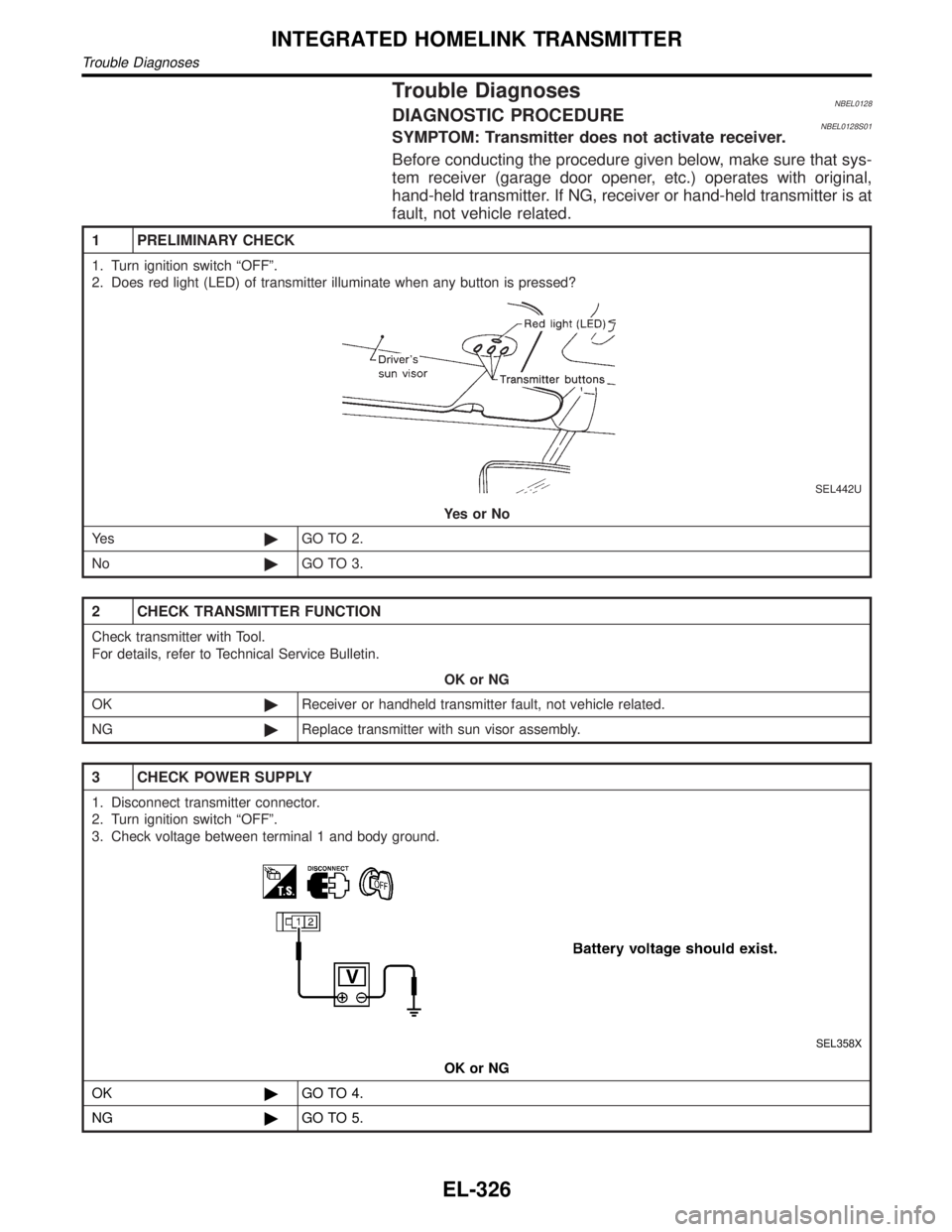
Trouble DiagnosesNBEL0128DIAGNOSTIC PROCEDURENBEL0128S01SYMPTOM: Transmitter does not activate receiver.
Before conducting the procedure given below, make sure that sys-
tem receiver (garage door opener, etc.) operates with original,
hand-held transmitter. If NG, receiver or hand-held transmitter is at
fault, not vehicle related.
1 PRELIMINARY CHECK
1. Turn ignition switch ªOFFº.
2. Does red light (LED) of transmitter illuminate when any button is pressed?
SEL442U
YesorNo
Ye s©GO TO 2.
No©GO TO 3.
2 CHECK TRANSMITTER FUNCTION
Check transmitter with Tool.
For details, refer to Technical Service Bulletin.
OK or NG
OK©Receiver or handheld transmitter fault, not vehicle related.
NG©Replace transmitter with sun visor assembly.
3 CHECK POWER SUPPLY
1. Disconnect transmitter connector.
2. Turn ignition switch ªOFFº.
3. Check voltage between terminal 1 and body ground.
SEL358X
OK or NG
OK©GO TO 4.
NG©GO TO 5.
INTEGRATED HOMELINK TRANSMITTER
Trouble Diagnoses
EL-326
Page 1516 of 2395

SEL331X
CONSULT-IINBEL0223CONSULT-II INSPECTION PROCEDURENBEL0223S011. Turn ignition switch OFF.
2. Insert IVIS (NATS) program card into CONSULT-II.
: Program card
NATS (UEN99A)
3. Connect CONSULT-II to data link connector.
SEL762W
4. Turn ignition switch ON.
5. Touch ªSTARTº.
SEL851W
6. Select ªNATS V.5.0º.
SEL363X
7. Perform each diagnostic test mode according to each service
procedure.
For further information, see the CONSULT-II Operation
Manual, IVIS/NVIS.
CONSULT-II DIAGNOSTIC TEST MODE FUNCTIONNBEL0223S02
CONSULT-II DIAGNOSTIC TEST
MODEDescription
C/U INITIALIZATION When replacing any of the following three components, C/U initialization and re-registration
of all IVIS (NATS) ignition keys are necessary.
[IVIS (NATS) ignition key/IMMU/ECM]
SELF-DIAG RESULTS Detected items (screen terms) are as shown in the chart EL-332.
GI
MA
EM
LC
EC
FE
AT
TF
PD
AX
SU
BR
ST
RS
BT
HA
SC
IDX
IVIS (INFINITI VEHICLE IMMOBILIZER SYSTEM Ð NATS)
CONSULT-II
EL-331
Page 1533 of 2395

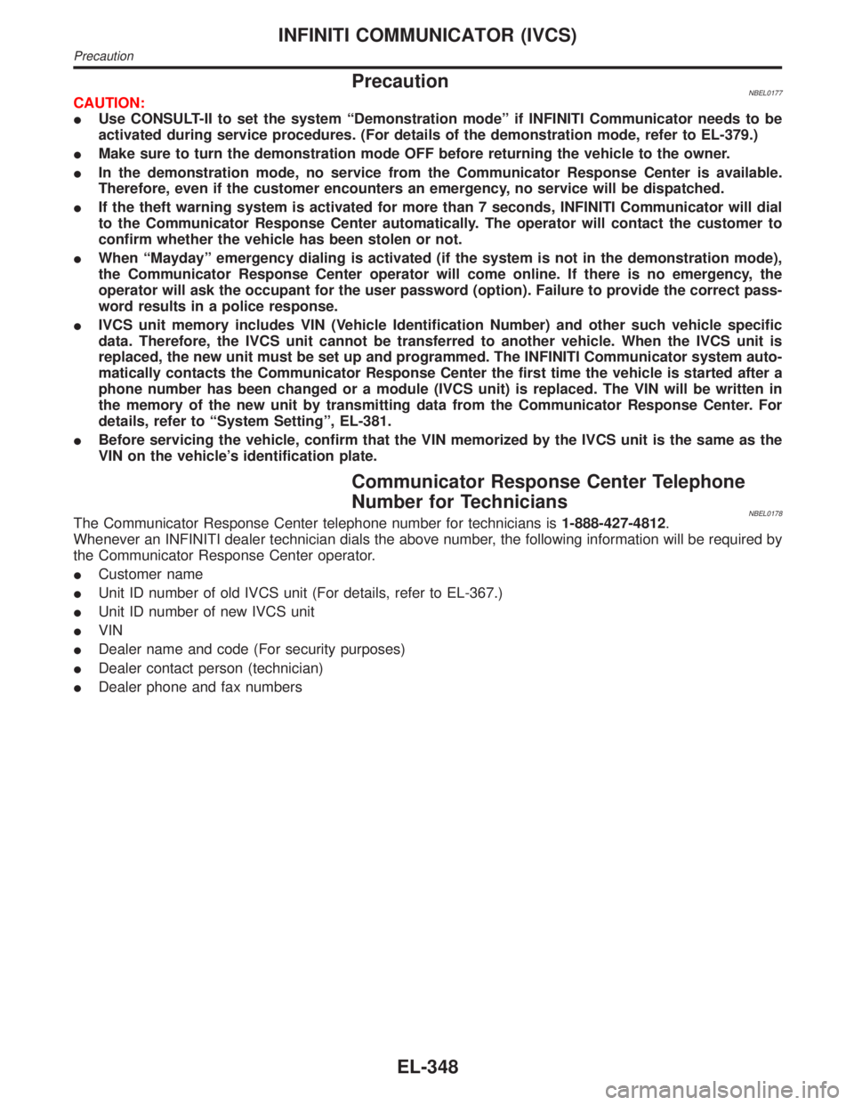
PrecautionNBEL0177CAUTION:
IUse CONSULT-II to set the system ªDemonstration modeº if INFINITI Communicator needs to be
activated during service procedures. (For details of the demonstration mode, refer to EL-379.)
IMake sure to turn the demonstration mode OFF before returning the vehicle to the owner.
IIn the demonstration mode, no service from the Communicator Response Center is available.
Therefore, even if the customer encounters an emergency, no service will be dispatched.
IIf the theft warning system is activated for more than 7 seconds, INFINITI Communicator will dial
to the Communicator Response Center automatically. The operator will contact the customer to
confirm whether the vehicle has been stolen or not.
IWhen ªMaydayº emergency dialing is activated (if the system is not in the demonstration mode),
the Communicator Response Center operator will come online. If there is no emergency, the
operator will ask the occupant for the user password (option). Failure to provide the correct pass-
word results in a police response.
IIVCS unit memory includes VIN (Vehicle Identification Number) and other such vehicle specific
data. Therefore, the IVCS unit cannot be transferred to another vehicle. When the IVCS unit is
replaced, the new unit must be set up and programmed. The INFINITI Communicator system auto-
matically contacts the Communicator Response Center the first time the vehicle is started after a
phone number has been changed or a module (IVCS unit) is replaced. The VIN will be written in
the memory of the new unit by transmitting data from the Communicator Response Center. For
details, refer to ªSystem Settingº, EL-381.
IBefore servicing the vehicle, confirm that the VIN memorized by the IVCS unit is the same as the
VIN on the vehicle's identification plate.
Communicator Response Center Telephone
Number for Technicians
NBEL0178The Communicator Response Center telephone number for technicians is1-888-427-4812.
Whenever an INFINITI dealer technician dials the above number, the following information will be required by
the Communicator Response Center operator.
ICustomer name
IUnit ID number of old IVCS unit (For details, refer to EL-367.)
IUnit ID number of new IVCS unit
IVIN
IDealer name and code (For security purposes)
IDealer contact person (technician)
IDealer phone and fax numbers
INFINITI COMMUNICATOR (IVCS)
Precaution
EL-348
Page 1536 of 2395

SYSTEM LIMITATIONSNBEL0180S03Service AreaNBEL0180S0301Depending on the cellular provider chosen, service is provided in
the 48 contiguous states. Service is not available in Alaska, Hawaii,
Canada, or Mexico. The Communicator Response Center will not
be able to locate the customer's vehicle outside of the continental
United States.
Inoperative if Cellular Phone is Inactive or InoperativeNBEL0180S0302INFINITI Communicator will be inoperative if the customer does not
have an active account with cellular provider, since INFINITI Com-
municator relies on the cellular network. When the INFINITI Com-
municator system is outside of cellular service, the ªNO SERVICEº
indicator will illuminate. If you try to activate INFINITI
Communicator, the REQUEST will be cancelled. Cellular phone
transmission may become temporarily disabled, or interrupted by
environmental factors like tunnels, bridges, or tall buildings. In such
cases, INFINITI Communicator will re-dial up to four times. After
several failed attempts, the system will quit dialing and return to
normal mode.
Inoperative if The System is in The Demonstraiton
Mode
NBEL0180S0303The INFINITI Communicator system remains in the demonstration
mode until the setup procedures are completed. If the system is
activated in this mode, the Communicator Response Center will
recognize this operation as a demonstration and will not provide
any service. The system can be changed to the demonstration
mode by using CONSULT-II to check the system operation. Do not
forget to turn off the demonstration mode after confirmation.
BatteryNBEL0180S0304Since INFINITI Communicator is powered by the vehicle's battery,
if the battery is removed, damaged or discharged, the system will
not work.
Inopertive if Cellular System is BusyNBEL0180S0305When INFINITI Communicator tries to contact the Communicator
Response Center, but the cellular network is busy, the system
attempts to re-dial for up to two hours. This time varies greatly
depending on the cellular network and cellular signal strength. The
system resets to ready when the system completes the re-dialing
attempts.
RoamingNBEL0180S0306If the customer's cellular provider does not have a roaming agree-
ment with the provider where the vehicle locates, it may not be
possible to use the lines of a different cellular provider. Therefore,
it is impossible that INFINITI Communicator will contact the Com-
municator Response Center.
Special Cellular FeaturesNBEL0180S0307Some cellular carriers offer custom phone numbers that are
assigned a Personal Identification Number (PIN). The cellular
phone user is required to enter the PIN anytime a phone call is
made. The INFINITI Communicator system is not compatible with
the PIN feature. A PIN requirement on the cellular phone will cause
the INFINITI Communicator system to be inoperative.
Other special features such as call waiting, voice mail, call
forwarding, etc. can interfere with INFINITI Communicator system
operation.
GI
MA
EM
LC
EC
FE
AT
TF
PD
AX
SU
BR
ST
RS
BT
HA
SC
IDX
INFINITI COMMUNICATOR (IVCS)
System Description (Cont'd)
EL-351
Page 1537 of 2395

Cellular Airwave InterferenceNBEL0180S0308At times someone other than the Communicator Response Center
operator may be heard. This is caused by Cellular Airwave Inter-
ference and is not caused by an INFINITI Communicator system
malfunction.
Possibility of Positioning Capability DegradedNBEL0180S0309Vehicle positioning is accomplished using the GPS (Global Posi-
tioning System). If the signal from the GPS satellite is obstructed
by a tunnel or building, positioning capability may be degraded or
lost. In this case, the last valid position obtained before the obstruc-
tion is transmitted to the Communicator Response Center. The
precision is also influenced by the location of GPS satellites.
Once the battery cable is disconnected, it will take about 5 minutes
to determine the vehicle location. This is because the memory
related to GPS is lost when the battery cable is disconnected.
OPERATIONNBEL0180S04One Touch ªInformationº DialingNBEL0180S0401IIf the vehicle becomes disabled due to problems such as
engine trouble, press the ªInformationº switch to connect to the
Communicator Response Center and receive the desired ser-
vice.
IWhen the indicator lamp on the switch lights up, it means that
the system has started to contact the Communicator
Response Center. (Voice communication with Communicator
Response Center operator is not available while DATA is being
transmitted even if the indicator lamp is lit.)
IWhen the indicator lamp blinks, it means that the system is
preparing for cellular connection or attempting to re-dial.
One Touch ªMaydayº Emergency DialingNBEL0180S0402IWhen an emergency occurs, press the ªMaydayº emergency
switch to connect to the Communicator Response Center. With
this report, the Communicator Response Center recognizes
that an emergency has occurred and provides necessary ser-
vice.
IThe operator will request a password (if the customer chooses
to establish a password). If the wrong password or if no pass-
word is provided, the Communicator Response Center will
assume the customer is in a duress situation and dispatch
police.
IWhen no voice reply is heard from the vehicle or the sound
heard indicates an emergency situation, the Communicator
Response Center will have the police rush to the scene.
IOther operations are the same as service dialing.
Automatic Air Bag Inflation NotificationNBEL0180S0403IWhen an air bag inflates, the air bag diagnosis sensor unit
sends the air bag inflation signal to the IVCS unit, and the
system automatically dials the Communicator Response Cen-
ter to report the occurrence of an accident.
Stolen Vehicle TrackingNBEL0180S0404IWhen a vehicle is stolen, the owner can contact the Commu-
nicator Response Center to attempt to locate the stolen
vehicle. The Communicator Response Center will activate the
stolen vehicle tracking to locate the vehicle. If the Communi-
cator Response Center successfully locates the vehicle, they
will contact the police to provide the location.
INFINITI COMMUNICATOR (IVCS)
System Description (Cont'd)
EL-352
Page 1539 of 2395

DATA TRANSMITTINGNBEL0180S05When contact to the Communicator Response Center is made,
vehicle sends electrical data including type of activation (i.e., emer-
gency call or alarm notification), vehicle location, time, etc.
SLEEP/WAKE UP CONTROLNBEL0180S063 minutes after the ignition switch is turned OFF, the system goes
into the SLEEP MODE to save battery power supply. Communica-
tion with Communicator Response Center is not available in the
SLEEP MODE.
To wake up the system, perform either of the following operations.
ITurn Ignition switch ON.
IPull back door outside handle for more than 10 seconds.
(Operation for door unlock function)
SEL532V
INDICATOR LAMPS OPERATIONNBEL0180S07The system status is displayed as below by the indicator lamps.
Indicator Condition Description
MAYDAYBlinks.System is trying to acquire an available cellu-
lar channel by ªMaydayº switch operation.
Lights up.
(See NOTE.)System is connected to a cellular channel and
is communicating information to the Commu-
nicator Response Center.
INFORMA-
TIONBlinks.System is trying to acquire an available cellu-
lar channel by ªInformationº switch operation.
Lights up.
(See NOTE.)System is connected to a cellular channel and
is communicating information to the Commu-
nicator Response Center.
REDIALLights up. Re-dialing
Blinks. Waiting for re-dial
NO SERVICE Lights up.Out of CELLULAR PHONE service area or
signal is too weak.
NOTE:
IWhen connection to Communicator Response Center by
re-dial ends in failure, all the indicators are turned off.
IAll indicators illuminate for up to 30 seconds or more
when ignition switch is turned from OFF to ON and the
system performs a self check.
IIf both of MAYDAY and INFORMATION indicators do not
turn off 30 seconds or more after the ignition switch is
turned to ON, the system is malfunctioning.
AUTOMATIC RE-DIAL/AUTO RESET TO READYNBEL0180S08IWhen INFINITI Communicator tries to contact the Communi-
cator Response Center, but the cellular network is busy, the
system attempts to dial for up to 2 hours. This time varies
INFINITI COMMUNICATOR (IVCS)
System Description (Cont'd)
EL-354