service INFINITI QX4 2001 Factory Service Manual
[x] Cancel search | Manufacturer: INFINITI, Model Year: 2001, Model line: QX4, Model: INFINITI QX4 2001Pages: 2395, PDF Size: 43.2 MB
Page 937 of 2395

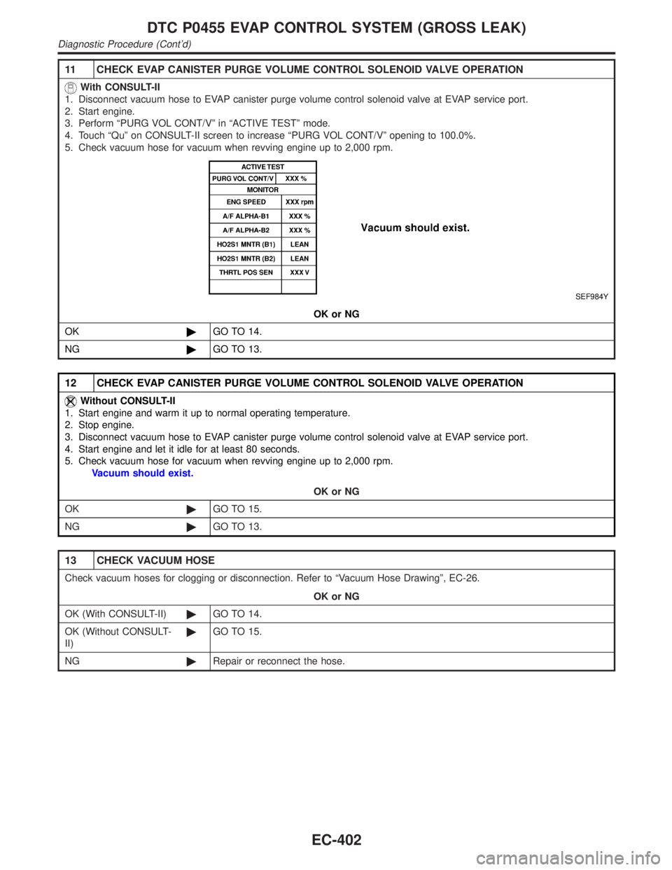
11 CHECK EVAP CANISTER PURGE VOLUME CONTROL SOLENOID VALVE OPERATION
With CONSULT-II
1. Disconnect vacuum hose to EVAP canister purge volume control solenoid valve at EVAP service port.
2. Start engine.
3. Perform ªPURG VOL CONT/Vº in ªACTIVE TESTº mode.
4. Touch ªQuº on CONSULT-II screen to increase ªPURG VOL CONT/Vº opening to 100.0%.
5. Check vacuum hose for vacuum when revving engine up to 2,000 rpm.
SEF984Y
OK or NG
OK©GO TO 14.
NG©GO TO 13.
12 CHECK EVAP CANISTER PURGE VOLUME CONTROL SOLENOID VALVE OPERATION
Without CONSULT-II
1. Start engine and warm it up to normal operating temperature.
2. Stop engine.
3. Disconnect vacuum hose to EVAP canister purge volume control solenoid valve at EVAP service port.
4. Start engine and let it idle for at least 80 seconds.
5. Check vacuum hose for vacuum when revving engine up to 2,000 rpm.
Vacuum should exist.
OK or NG
OK©GO TO 15.
NG©GO TO 13.
13 CHECK VACUUM HOSE
Check vacuum hoses for clogging or disconnection. Refer to ªVacuum Hose Drawingº, EC-26.
OK or NG
OK (With CONSULT-II)©GO TO 14.
OK (Without CONSULT-
II)©GO TO 15.
NG©Repair or reconnect the hose.
DTC P0455 EVAP CONTROL SYSTEM (GROSS LEAK)
Diagnostic Procedure (Cont'd)
EC-402
Page 1063 of 2395

place or refilling/draining fuel until the output voltage condition
of the ªFUEL LEVEL SEº meets within the range above and
leave the vehicle for more than 1 hour. Then start from step 1).
3) Turn ignition switch ªOFFº and wait at least 5 seconds.
4) Turn ignition switch ªONº.
5) Select ªEVAP VERY/SML LEAK P1441º of ªEVAPORATIVE
SYSTEMº in ªDTC WORK SUPPORTº mode with CONSULT-
II.
Follow the instruction displayed.
6) Make sure that ªOKº is displayed.
If ªNGº is displayed, refer to ªDiagnostic Procedureº, EC-529.
NOTE:
IIf the engine speed cannot be maintained within the range
displayed on CONSULT-II screen, go to ªBasic
inspectionº, EC-101.
IMake sure that EVAP hoses are connected to EVAP canis-
ter purge volume control solenoid valve properly.
OVERALL FUNCTION CHECKNBEC0317S05With GST
Use this procedure to check the overall function of the EVAP very
small leak function. During this check, a 1st trip DTC might not be
confirmed.
SEF462UA
CAUTION:
INever use compressed air, doing so may damage the
EVAP system.
IDo not start engine.
IDo not exceeded 4.12 kPa (0.042 kg/cm
2, 0.6 psi).
1) Attach the EVAP service port adapter securely to the EVAP
service port.
2) Set the pressure pump and a hose.
3) Also set a vacuum gauge via 3-way connector and a hose.
4) Turn ignition switch ªONº.
5) Connect GST and select mode 8.
6) Using mode 8 control the EVAP canister vent control valve
(close) and vacuum cut valve bypass valve (open).
7) Apply pressure and make sure the following conditions are
satisfied.
Pressure to be applied: 2.7 kPa (20 mmHg, 0.79 inHg)
Time to be waited after the pressure drawn in to the EVAP
system and the pressure to be dropped: 60 seconds and
the pressure should not be dropped more than 0.4 kPa (3
mmHg, 0.12 inHg)
If NG, go to diagnostic procedure, EC-529.
NOTE:
For more information, refer to GST instruction manual.
DTC P1441 EVAP CONTROL SYSTEM (VERY SMALL LEAK)
DTC Confirmation Procedure (Cont'd)
EC-528
Page 1066 of 2395

5 INSTALL THE PRESSURE PUMP
To locate the EVAP leak, install EVAP service port adapter and pressure pump to EVAP service port securely.
SEF983Y
SEF916U
NOTE:
Improper installation of the EVAP service port adapter to the EVAP service port may cause leaking.
Models with CONSULT-II©GO TO 6.
Models without CON-
SULT-II©GO TO 7.
GI
MA
EM
LC
FE
AT
TF
PD
AX
SU
BR
ST
RS
BT
HA
SC
EL
IDX
DTC P1441 EVAP CONTROL SYSTEM (VERY SMALL LEAK)
Diagnostic Procedure (Cont'd)
EC-531
Page 1068 of 2395

7 CHECK FOR EVAP LEAK
Without CONSULT-II
1. Turn ignition switch ªOFFº.
2. Apply 12 volts DC to EVAP canister vent control valve. The valve will close. (Continue to apply 12 volts until the end of
test.)
SEF598U
3. Apply 12 volts DC to vacuum cut valve bypass valve. The valve will open. (Continue to apply 12V until the end of test.)
SEF599U
4. Pressurize the EVAP line using pressure pump with 1.3 to 2.7 kPa (10 to 20 mmHg, 0.39 to 0.79 inHg), then remove
pump and EVAP service port adapter.
NOTE:
INever use compressed air or a high pressure pump.
IDo not exceed 4.12 kPa (0.042 kg/cm
2, 0.6 psi) of pressure in the system.
5. Using EVAP leak detector, locate the EVAP leak. For the leak detector, refer to the instruction manual for more details.
Refer to ªEVAPORATIVE EMISSION LINE DRAWINGº, EC-36.
SEF200U
OK or NG
OK©GO TO 8.
NG©Repair or replace.
GI
MA
EM
LC
FE
AT
TF
PD
AX
SU
BR
ST
RS
BT
HA
SC
EL
IDX
DTC P1441 EVAP CONTROL SYSTEM (VERY SMALL LEAK)
Diagnostic Procedure (Cont'd)
EC-533
Page 1070 of 2395

11 CHECK EVAP CANISTER
Weigh the EVAP canister with the EVAP canister vent control valve attached.
The weight should be less than 1.8 kg (4.0 lb).
OK or NG
OK (With CONSULT-II)©GO TO 13.
OK (Without CONSULT-
II)©GO TO 14.
NG©GO TO 12.
12 DETECT MALFUNCTIONING PART
Check the following.
IEVAP canister for damage
IEVAP hose between EVAP canister and water separator for clogging or poor connection
©Repair hose or replace EVAP canister.
13 CHECK EVAP CANISTER PURGE VOLUME CONTROL SOLENOID VALVE OPERATION
With CONSULT-II
1. Disconnect vacuum hose to EVAP canister purge volume control solenoid valve at EVAP service port.
2. Start engine.
3. Perform ªPURG VOL CONT/Vº in ªACTIVE TESTº mode.
4. Touch ªQuº on CONSULT-II screen to increase ªPURG VOL CONT/Vº opening to 100.0%.
5. Check vacuum hose for vacuum when revving engine up to 2,000 rpm.
SEF984Y
OK or NG
OK©GO TO 16.
NG©GO TO 15.
14 CHECK EVAP CANISTER PURGE VOLUME CONTROL SOLENOID VALVE OPERATION
Without CONSULT-II
1. Start engine and warm it up to normal operating temperature.
2. Stop engine.
3. Disconnect vacuum hose to EVAP canister purge volume control solenoid valve at EVAP service port.
4. Start engine and let it idle for at least 80 seconds.
5. Check vacuum hose for vacuum when revving engine up to 2,000 rpm.
Vacuum should exist.
OK or NG
OK©GO TO 17.
NG©GO TO 15.
GI
MA
EM
LC
FE
AT
TF
PD
AX
SU
BR
ST
RS
BT
HA
SC
EL
IDX
DTC P1441 EVAP CONTROL SYSTEM (VERY SMALL LEAK)
Diagnostic Procedure (Cont'd)
EC-535
Page 1099 of 2395

Diagnostic Procedure=NBEC0337
1 CHECK EVAP CANISTER
1. Turn ignition switch ªOFFº.
2. Check EVAP canister for cracks.
OK or NG
OK (With CONSULT-II)©GO TO 2.
OK (Without CONSULT-
II)©GO TO 3.
NG©Replace EVAP canister.
2 CHECK PURGE FLOW
With CONSULT-II
1. Disconnect vacuum hose connected to EVAP canister purge volume control solenoid valve at EVAP service port and
install vacuum gauge.
SEF983Y
2. Start engine and let it idle.
3. Select ªPURG VOL CONT/Vº in ªACTIVE TESTº mode with CONSULT-II.
4. Rev engine up to 2,000 rpm.
5. Touch ªQdº and ªQuº on CONSULT-II screen to adjust ªPURG VOL CONT/Vº opening and check vacuum existence.
SEF012Z
OK or NG
OK©GO TO 7.
NG©GO TO 4.
DTC P1447 EVAPORATIVE EMISSION (EVAP) CONTROL SYSTEM PURGE
FLOW MONITORING
Diagnostic Procedure
EC-564
Page 1100 of 2395

3 CHECK PURGE FLOW
Without CONSULT-II
1. Start engine and warm it up to normal operating temperature.
2. Stop engine.
3. Disconnect vacuum hose connected to EVAP canister purge volume control solenoid valve at EVAP service port and
install vacuum gauge.
SEF983Y
4. Start engine and let it idle for at least 80 seconds.
5. Check vacuum gauge indication when revving engine up to 2,000 rpm.
Vacuum should exist.
6. Release the accelerator pedal fully and let idle.
Vacuum should not exist.
OK or NG
OK©GO TO 7.
NG©GO TO 4.
4 CHECK EVAP PURGE LINE
1. Turn ignition switch ªOFFº.
2. Check EVAP purge line for improper connection or disconnection.
Refer to ªEVAPORATIVE EMISSION LINE DRAWINGº, EC-36.
OK or NG
OK (With CONSULT-II)©GO TO 5.
OK (Without CONSULT-
II)©GO TO 6.
NG©Repair it.
GI
MA
EM
LC
FE
AT
TF
PD
AX
SU
BR
ST
RS
BT
HA
SC
EL
IDX
DTC P1447 EVAPORATIVE EMISSION (EVAP) CONTROL SYSTEM PURGE
FLOW MONITORING
Diagnostic Procedure (Cont'd)
EC-565
Page 1101 of 2395

5 CHECK EVAP PURGE HOSE AND PURGE PORT
1. Disconnect purge hoses connected to EVAP service portAand EVAP canister purge volume control solenoid valveB.
SEF367U
2. Blow air into each hose and EVAP purge portC.
3. Check that air flows freely.
SEF368U
OK or NG
OK©GO TO 6.
NG©Repair or clean hoses and/or purge port.
6 CHECK EVAP CANISTER PURGE VOLUME CONTROL SOLENOID VALVE
With CONSULT-II
1. Start engine.
2. Perform ªPURG VOL CONT/Vº in ªACTIVE TESTº mode with CONSULT-II. Check that engine speed varies according
to the valve opening.
SEF985Y
OK or NG
OK©GO TO 8.
NG©GO TO 7.
DTC P1447 EVAPORATIVE EMISSION (EVAP) CONTROL SYSTEM PURGE
FLOW MONITORING
Diagnostic Procedure (Cont'd)
EC-566
Page 1184 of 2395

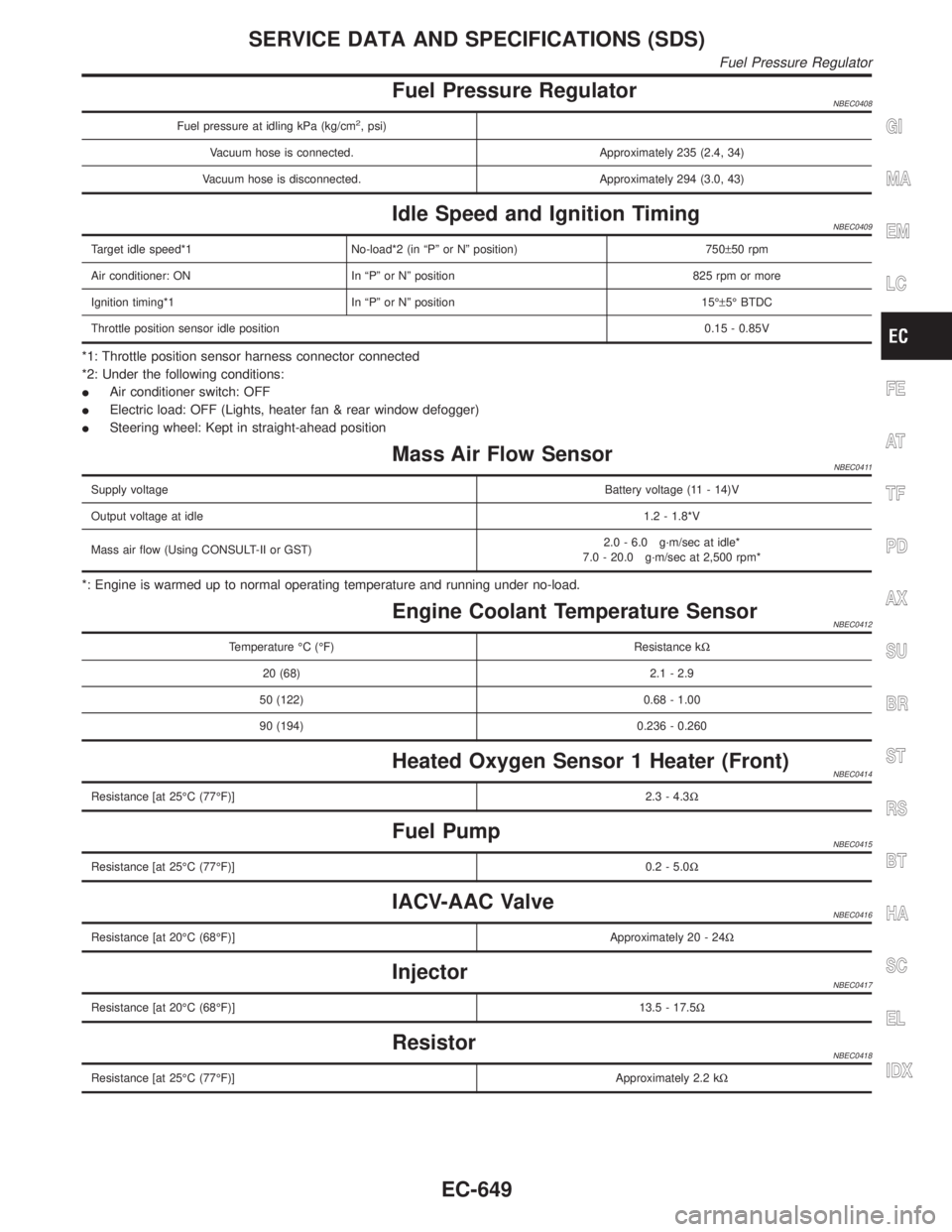
Fuel Pressure RegulatorNBEC0408
Fuel pressure at idling kPa (kg/cm2, psi)
Vacuum hose is connected. Approximately 235 (2.4, 34)
Vacuum hose is disconnected. Approximately 294 (3.0, 43)
Idle Speed and Ignition TimingNBEC0409
Target idle speed*1 No-load*2 (in ªPº or Nº position) 750±50 rpm
Air conditioner: ON In ªPº or Nº position 825 rpm or more
Ignition timing*1 In ªPº or Nº position 15ɱ5É BTDC
Throttle position sensor idle position0.15 - 0.85V
*1: Throttle position sensor harness connector connected
*2: Under the following conditions:
IAir conditioner switch: OFF
IElectric load: OFF (Lights, heater fan & rear window defogger)
ISteering wheel: Kept in straight-ahead position
Mass Air Flow SensorNBEC0411
Supply voltageBattery voltage (11 - 14)V
Output voltage at idle1.2 - 1.8*V
Mass air flow (Using CONSULT-II or GST)2.0 - 6.0 g´m/sec at idle*
7.0 - 20.0 g´m/sec at 2,500 rpm*
*: Engine is warmed up to normal operating temperature and running under no-load.
Engine Coolant Temperature SensorNBEC0412
Temperature ÉC (ÉF) Resistance kW
20 (68) 2.1 - 2.9
50 (122) 0.68 - 1.00
90 (194) 0.236 - 0.260
Heated Oxygen Sensor 1 Heater (Front)NBEC0414
Resistance [at 25ÉC (77ÉF)]2.3 - 4.3W
Fuel PumpNBEC0415
Resistance [at 25ÉC (77ÉF)]0.2 - 5.0W
IACV-AAC ValveNBEC0416
Resistance [at 20ÉC (68ÉF)]Approximately 20 - 24W
InjectorNBEC0417
Resistance [at 20ÉC (68ÉF)]13.5 - 17.5W
ResistorNBEC0418
Resistance [at 25ÉC (77ÉF)]Approximately 2.2 kW
GI
MA
EM
LC
FE
AT
TF
PD
AX
SU
BR
ST
RS
BT
HA
SC
EL
IDX
SERVICE DATA AND SPECIFICATIONS (SDS)
Fuel Pressure Regulator
EC-649
Page 1185 of 2395

Throttle Position SensorNBEC0419
Throttle valve conditionsVoltage
(at normal operating temperature,
engine off, ignition switch ON,
throttle opener disengaged)
Completely closed (a)0.15 - 0.85V
Partially openBetween (a) and (b)
Completely open (b)3.5 - 4.7V
Calculated Load ValueNBEC0420
Calculated load value % (Using CONSULT-II or GST)
At idle14.0 - 33.0
At 2,500 rpm12.0 - 25.0
Intake Air Temperature SensorNBEC0421
Temperature ÉC (ÉF) Resistance kW
20 (68)2.1 - 2.9
80 (176)0.27 - 0.38
Heated Oxygen Sensor 2 Heater (Rear)NBEC0422
Resistance [at 25ÉC (77ÉF)]2.3 - 4.3W
Crankshaft Position Sensor (REF)NBEC0423
Resistance [at 20ÉC (68ÉF)]470 - 570W
Fuel Tank Temperature SensorNBEC0424
Temperature ÉC (ÉF) Resistance kW
20 (68)2.3 - 2.7
50 (122)0.79 - 0.90
Camshaft Position Sensor (PHASE)NBEC0639
Resistance [at 20ÉC (68ÉF)]HITACHI make 1,440 - 1,760W
MITSUBISHI make 2,090 - 2,550W
SERVICE DATA AND SPECIFICATIONS (SDS)
Throttle Position Sensor
EC-650