air condition INFINITI QX4 2001 Factory Service Manual
[x] Cancel search | Manufacturer: INFINITI, Model Year: 2001, Model line: QX4, Model: INFINITI QX4 2001Pages: 2395, PDF Size: 43.2 MB
Page 1562 of 2395

TELEPHONE STEERING SWITCH CHECK=NBEL0184S14
1 CHECK POWER SUPPLY FOR STEERING SWITCH
Check power supply for steering switch.
Does horn work?
Ye s©Check the following.
I10A fuse (No. 54, located in fuse and fusible link box)
IHorn relay
IHarness for open or short
No©GO TO 2.
2 CHECK STEERING SWITCH SUB-HARNESS
1. Remove driver's air bag module. For removal procedure, refer to RS section.
2. Check steering switch sub-harness for open or short and ground screw.
For details of the harness circuit, refer to ªSTEERING SWITCHº, EL-30.
OK or NG
OK©Check harness for open or short between telephone steering switch and IVCS unit. If the
circuit is OK, replace telephone steering switch.
NG©Replace or repair the harness.
Trouble Diagnoses for Intermittent IncidentNBEL0185DESCRIPTIONNBEL0185S01An intermittent incident may be occurring if all of the following conditions exist.
IBoth ªMAYDAYº emergency and ªINFORMATIONº indicators have shown that the system is malfunction-
ing.
ICONSULT-II self-diagnosis result screen indicates a trouble code with ªTIME=1orgreaterº.
IThe INFINITI Communicator system has not been previously serviced.
To find out the cause of a malfunction, follow the procedures shown below.
GI
MA
EM
LC
EC
FE
AT
TF
PD
AX
SU
BR
ST
RS
BT
HA
SC
IDX
INFINITI COMMUNICATOR (IVCS)
Trouble Diagnoses (Cont'd)
EL-377
Page 1608 of 2395

This Condition is Not Abnormal=NBEL0235EXAMPLE OF BASIC OPERATIONAL ERRORSNBEL0235S01
Symptom Possible cause Repair order
No image is dis-
played.Monitor brightness control is set to full dark. Readjust monitor brightness.
Map does not appear
on display.Map CD is not inserted or inserted upside down. Insert the map CD with the label facing up.
Map mode is turned OFF. Press the ªMAPº button.
No guide tone is
heard.
Voice guide adjustment OFF/Volume is set to the
lowest or highest level.Adjust the voice guide level.
Voice guide volume
is too high or too low.
Dark display/Slow
image movementLow vehicle interior temperatureWait until vehicle interior temperature rises to appro-
priate level.
Small black or white
dots appear on the
screen.Unique liquid crystal display phenomena No problem
ªUnable to read CDº
message appears
only during specified
operation.Map CD surface is tainted/CD surface is partially
scratched.Check map CD surface. If dirty, wipe clean with a
soft cloth.
If map CD surface is damaged, replace the CD.
Area place names are not displayed.
If area place names do not appear on the map display, these names may not be available. Use the BIRD-
VIEW
Tflat surface map display function. Display output may differ. Note the items related to BIRDVIEWT
below.
IPriority is given to the display of place names in the direction of vehicle travel.
IExtended display of vehicle travel distance for both surfaces and steering angle (flat directional changes).
This phenomenon disappears after the display image has been replaced by another one.
IThe names of route and area might vary between the immediate front area and distance front area.
IAlphanumeric display characters are limited to maintain display simplicity and clarity. Display details may
differ with time and place.
IIdentical place and road names may appear on the display at more than one location.
GI
MA
EM
LC
EC
FE
AT
TF
PD
AX
SU
BR
ST
RS
BT
HA
SC
IDX
NAVIGATION SYSTEM
This Condition is Not Abnormal
EL-423
Page 1615 of 2395

IThe enlarged intersection map may display an ªUnknown Streetº message at some street intersections.
IBecause of road configuration, etc. the guide may finish early. If this occurs, follow the marker to reach
your destination.
IDestination area side information (left side and right side) may differ from actual conditions because of
data error.
Unable to Set Destination, Way Point, and/or Menu ItemsNBEL0235S0301
Symptom Possible cause Repair order
Unable to search way points in
re-search modeA way point already crossed or determined to
have been crossed.If you desire to pass through a way point for a
second time, reperform route edit.
Turn list is not displayed.Route search does not occur.Set designation areas and perform route
search.
Car marker does not appear on recom-
mended route.Drive on the recommended route.
Route guide is canceled.Turn the route guide ON. (Push ªVOICEº
switch.)
Automatic search does not func-
tion.Vehicle is not running on search object route
(road indicated by orange, brown or red line).Drive the vehicle on the search object route
or perform a manual route search. Note that
all routes will be re-searched at this time.
Unable to select detour route. Vehicle is not running on recommended route.Use the ªRE-ROUTEº mode to search again
or return to the recommended route.
Detour route search results are
identical to previous search.All possible conditions were considered, but
results are the same.This is not abnormal.
Unable to set a way point.More than five way points have been previ-
ously set (and not cleared).More than five way points cannot be specified
at the same time. Break down into smaller
segments and perform search.
Unable to select starting point
during route edit.Starting point will normally be your present
location during route edit.This is not abnormal.
Cannot select certain menu items. While vehicle is running.Park the vehicle in a safe area and perform
operation.
Voice Guide InformationNBEL0235S0302
Symptom Possible cause Repair order
Voice guide does not function. Voice guide is only available at certain inter-
sections (marked with
). In some cases, the
guide is not available even when the vehicle
makes a turn.This is not abnormal.
Vehicle is not running on recommended route.Return to recommended route or reperform
route search.
Voice guide is OFF. Set voice guide to the ON position.
Route guide is canceled.Turn the route guide ON. (Push ªVOICEº
switch.)
The guide content does not corre-
spond to actual conditions.The content of the voice guide may vary
depending on the type of junction.Operate vehicle following the traffic rules and
regulation.
Route Search InformationNBEL0235S0303
Symptom Possible cause Repair order
Proceeding in desired direction.
However, route search in desired
direction does not function.Unable to find appropriate route in the desired
direction.This is not abnormal.
NAVIGATION SYSTEM
This Condition is Not Abnormal (Cont'd)
EL-430
Page 1616 of 2395

Symptom Possible cause Repair order
No route is displayed.No object route is searched near destination
area.Adjust position to wide road (brown) near des-
tination area. In an area where traffic direction
is displayed separately, pay close attention to
the direction of travel. Set the destination area
and the way point over the road.
Starting point and destination areas are very
near.Move destination areas away from starting
point on the screen.
Recommended route which has
been passed disappears from the
display.The recommended route is divided into indi-
vidual control segments. When way point 1 is
passed, the data from the starting point to the
way point 1 is erased.This is not abnormal.
Search recommends roundabout
route.There may be special conditions for roads
near the starting point and destination area
(one-way traffic, etc.). A roundabout route may
be displayed.Slightly change starting point and destination
area settings.
Landmark display does not show
actual conditions.Mistaken or missing map data may result in
erroneous display.Change map CD.
Recommended route drawn
slightly away from starting point,
way points, and destination area.Course search data may not exist for closely
positioned starting point, way points, and des-
tination area shown on the map. Route guide
starting point, way point, and destination point
may be separated.Set the destination area to the general route
(indicated by a thick brown line). However,
even if the selected route is a major one,
appropriate route search data may not be
available.
LOCATION OF CAR MARKERNBEL0235S04IIf the vehicle has been parked in a multi-level parking facility or underground parking facility, the car marker
position may be inaccurate immediately after exiting the parking facility.
IThe GPS accuracy is within±100 m (300 ft). Even when receiving conditions are excellent, further posi-
tional correction may not occur.
STREET INDICATIONNBEL0235S05IStreet names displayed on the map may differ from the actual street names.
IAn ªUnknown Streetº message may appear on the map in place of street name information.
RESEARCHNBEL0235S06IPosition may be searched by house number. However, the displayed position and street may differ from
the actual position and street.
IWhen position is searched using POI, the displayed position may differ from the actual position.
ISome data may not be available for new buildings and other structures in a map.
GPS ANTENNANBEL0235S07IDo not place metal objects above the GPS antenna mounted on the rear parcel shelf. This will cause
interference with signal reception.
IDo not place mobile telephones or vehicle radio transceivers in close proximity to the GPS antenna
mounted on the rear parcel shelf. This may cause interference with signal reception.
GI
MA
EM
LC
EC
FE
AT
TF
PD
AX
SU
BR
ST
RS
BT
HA
SC
IDX
NAVIGATION SYSTEM
This Condition is Not Abnormal (Cont'd)
EL-431
Page 1642 of 2395
NBEL0145
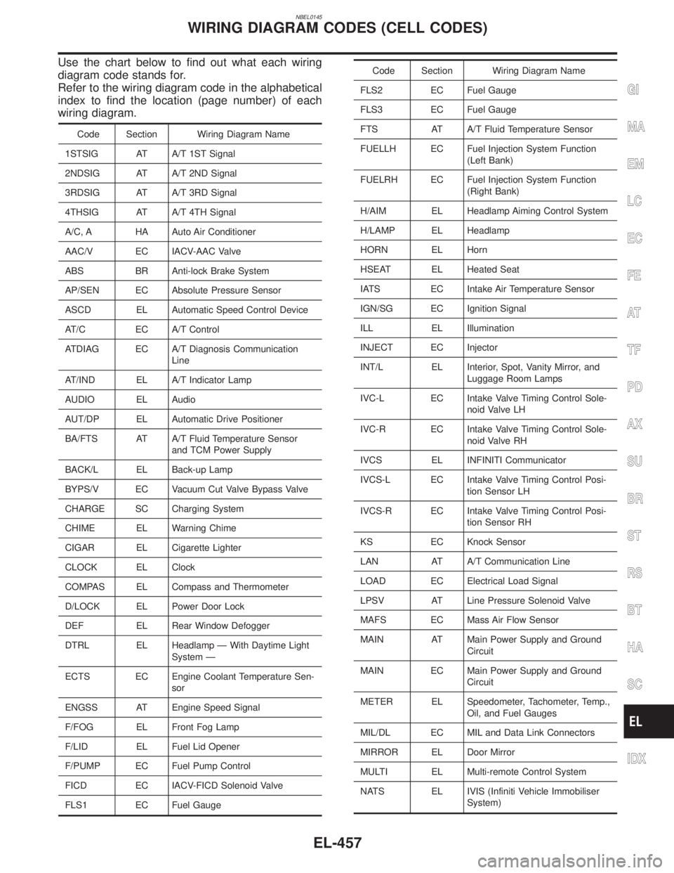
Use the chart below to find out what each wiring
diagram code stands for.
Refer to the wiring diagram code in the alphabetical
index to find the location (page number) of each
wiring diagram.
Code Section Wiring Diagram Name
1STSIG AT A/T 1ST Signal
2NDSIG AT A/T 2ND Signal
3RDSIG AT A/T 3RD Signal
4THSIG AT A/T 4TH Signal
A/C, A HA Auto Air Conditioner
AAC/V EC IACV-AAC Valve
ABS BR Anti-lock Brake System
AP/SEN EC Absolute Pressure Sensor
ASCD EL Automatic Speed Control Device
AT/C EC A/T Control
ATDIAG EC A/T Diagnosis Communication
Line
AT/IND EL A/T Indicator Lamp
AUDIO EL Audio
AUT/DP EL Automatic Drive Positioner
BA/FTS AT A/T Fluid Temperature Sensor
and TCM Power Supply
BACK/L EL Back-up Lamp
BYPS/V EC Vacuum Cut Valve Bypass Valve
CHARGE SC Charging System
CHIME EL Warning Chime
CIGAR EL Cigarette Lighter
CLOCK EL Clock
COMPAS EL Compass and Thermometer
D/LOCK EL Power Door Lock
DEF EL Rear Window Defogger
DTRL EL Headlamp Ð With Daytime Light
System Ð
ECTS EC Engine Coolant Temperature Sen-
sor
ENGSS AT Engine Speed Signal
F/FOG EL Front Fog Lamp
F/LID EL Fuel Lid Opener
F/PUMP EC Fuel Pump Control
FICD EC IACV-FICD Solenoid Valve
FLS1 EC Fuel Gauge
Code Section Wiring Diagram Name
FLS2 EC Fuel Gauge
FLS3 EC Fuel Gauge
FTS AT A/T Fluid Temperature Sensor
FUELLH EC Fuel Injection System Function
(Left Bank)
FUELRH EC Fuel Injection System Function
(Right Bank)
H/AIM EL Headlamp Aiming Control System
H/LAMP EL Headlamp
HORN EL Horn
HSEAT EL Heated Seat
IATS EC Intake Air Temperature Sensor
IGN/SG EC Ignition Signal
ILL EL Illumination
INJECT EC Injector
INT/L EL Interior, Spot, Vanity Mirror, and
Luggage Room Lamps
IVC-L EC Intake Valve Timing Control Sole-
noid Valve LH
IVC-R EC Intake Valve Timing Control Sole-
noid Valve RH
IVCS EL INFINITI Communicator
IVCS-L EC Intake Valve Timing Control Posi-
tion Sensor LH
IVCS-R EC Intake Valve Timing Control Posi-
tion Sensor RH
KS EC Knock Sensor
LAN AT A/T Communication Line
LOAD EC Electrical Load Signal
LPSV AT Line Pressure Solenoid Valve
MAFS EC Mass Air Flow Sensor
MAIN AT Main Power Supply and Ground
Circuit
MAIN EC Main Power Supply and Ground
Circuit
METER EL Speedometer, Tachometer, Temp.,
Oil, and Fuel Gauges
MIL/DL EC MIL and Data Link Connectors
MIRROR EL Door Mirror
MULTI EL Multi-remote Control System
NATS EL IVIS (Infiniti Vehicle Immobiliser
System)
GI
MA
EM
LC
EC
FE
AT
TF
PD
AX
SU
BR
ST
RS
BT
HA
SC
IDX
WIRING DIAGRAM CODES (CELL CODES)
EL-457
Page 1652 of 2395
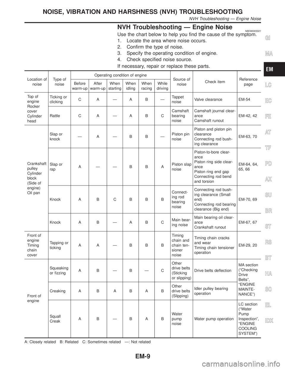
NVH Troubleshooting Ð Engine NoiseNBEM0005S01Use the chart below to help you find the cause of the symptom.
1. Locate the area where noise occurs.
2. Confirm the type of noise.
3. Specify the operating condition of engine.
4. Check specified noise source.
If necessary, repair or replace these parts.
Location of
noiseType of
noiseOperating condition of engine
Source of
noiseCheck itemReference
page Before
warm-upAfter
warm-upWhen
startingWhen
idlingWhen
racingWhile
driving
To p o f
engine
Rocker
cover
Cylinder
headTicking or
clickingC A ÐA BÐTappet
noiseValve clearance EM-54
Rattle C A Ð A B CCamshaft
bearing
noiseCamshaft journal clear-
ance
Camshaft runoutEM-42, 42
Crankshaft
pulley
Cylinder
block
(Side of
engine)
Oil panSlap or
knockÐ A ÐB BÐPiston pin
noisePiston and piston pin
clearance
Connecting rod bush-
ing clearanceEM-63, 70
Slap or
rapA ÐÐBBAPiston slap
noisePiston-to-bore clear-
ance
Piston ring side clear-
ance
Piston ring end gap
Connecting rod bend
and torsionEM-64, 64,
65, 66
Knock A B C B B BConnect-
ing rod
bearing
noiseConnecting rod bush-
ing clearance (Small
end)
Connecting rod bearing
clearance (Big end)EM-70, 69
Knock A B Ð A B CMain bear-
ing noiseMain bearing oil clear-
ance
Crankshaft runoutEM-67, 67
Front of
engine
Timing
chain
coverTapping or
tickingA A ÐBBBTiming
chain and
chain ten-
sioner
noiseTiming chain cracks
and wear
Timing chain tensioner
operationEM-29, 20
Front of
engineSqueaking
or fizzingA B ÐBÐCOther
drive belts
(Sticking
or slipping)Drive belts deflectionMA section
(ªChecking
Drive
Beltsº,
ªENGINE
MAINTE-
NANCEº) Creaking A BABABOther
drive belts
(Slipping)Idler pulley bearing
operation
Squall
CreakA B ÐBABWater
pump
noiseWater pump operationLC section
(ªWater
Pump
Inspectionº,
ªENGINE
COOLING
SYSTEMº)
A: Closely related B: Related C: Sometimes related Ð: Not related
GI
MA
LC
EC
FE
AT
TF
PD
AX
SU
BR
ST
RS
BT
HA
SC
EL
IDX
NOISE, VIBRATION AND HARSHNESS (NVH) TROUBLESHOOTING
NVH Troubleshooting Ð Engine Noise
EM-9
Page 1688 of 2395
SEM934C
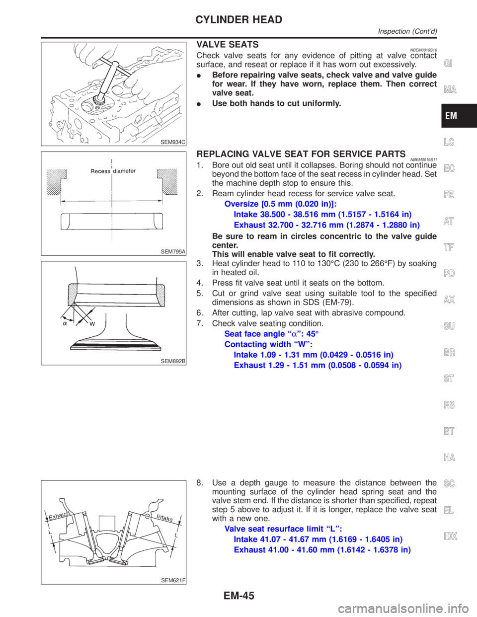
VALVE SEATSNBEM0019S10Check valve seats for any evidence of pitting at valve contact
surface, and reseat or replace if it has worn out excessively.
IBefore repairing valve seats, check valve and valve guide
for wear. If they have worn, replace them. Then correct
valve seat.
IUse both hands to cut uniformly.
SEM795A
REPLACING VALVE SEAT FOR SERVICE PARTSNBEM0019S111. Bore out old seat until it collapses. Boring should not continue
beyond the bottom face of the seat recess in cylinder head. Set
the machine depth stop to ensure this.
2. Ream cylinder head recess for service valve seat.
Oversize [0.5 mm (0.020 in)]:
Intake 38.500 - 38.516 mm (1.5157 - 1.5164 in)
Exhaust 32.700 - 32.716 mm (1.2874 - 1.2880 in)
Be sure to ream in circles concentric to the valve guide
center.
This will enable valve seat to fit correctly.
SEM892B
3. Heat cylinder head to 110 to 130ÉC (230 to 266ÉF) by soaking
in heated oil.
4. Press fit valve seat until it seats on the bottom.
5. Cut or grind valve seat using suitable tool to the specified
dimensions as shown in SDS (EM-79).
6. After cutting, lap valve seat with abrasive compound.
7. Check valve seating condition.
Seat face angle ªaº: 45É
Contacting width ªWº:
Intake 1.09 - 1.31 mm (0.0429 - 0.0516 in)
Exhaust 1.29 - 1.51 mm (0.0508 - 0.0594 in)
SEM621F
8. Use a depth gauge to measure the distance between the
mounting surface of the cylinder head spring seat and the
valve stem end. If the distance is shorter than specified, repeat
step 5 above to adjust it. If it is longer, replace the valve seat
with a new one.
Valve seat resurface limit ªLº:
Intake 41.07 - 41.67 mm (1.6169 - 1.6405 in)
Exhaust 41.00 - 41.60 mm (1.6142 - 1.6378 in)
GI
MA
LC
EC
FE
AT
TF
PD
AX
SU
BR
ST
RS
BT
HA
SC
EL
IDX
CYLINDER HEAD
Inspection (Cont'd)
EM-45
Page 1702 of 2395
Rear Engine MountingNBEM0042S0102
SEM459G
SEM605G
SEM461G
SEM324F
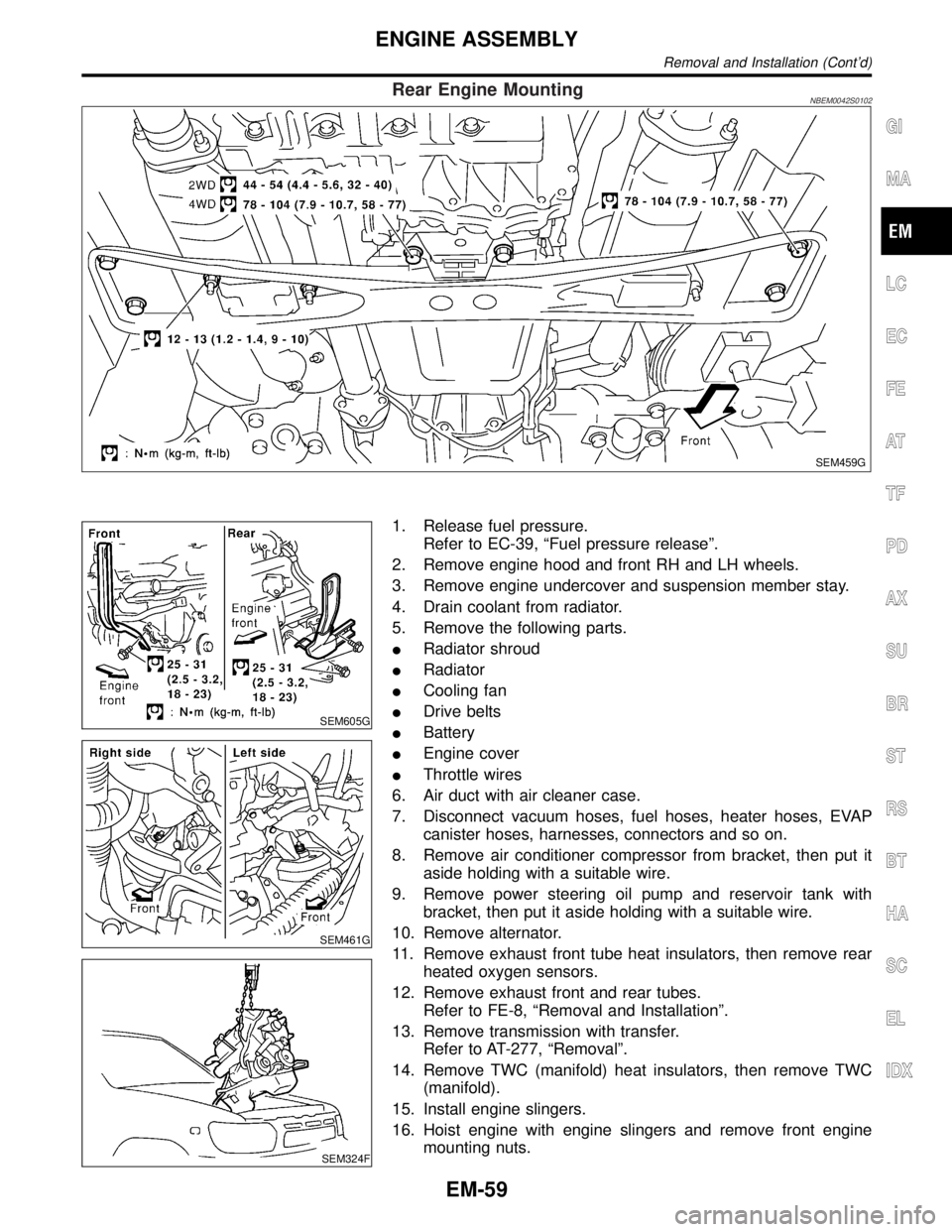
1. Release fuel pressure.
Refer to EC-39, ªFuel pressure releaseº.
2. Remove engine hood and front RH and LH wheels.
3. Remove engine undercover and suspension member stay.
4. Drain coolant from radiator.
5. Remove the following parts.
IRadiator shroud
IRadiator
ICooling fan
IDrive belts
IBattery
IEngine cover
IThrottle wires
6. Air duct with air cleaner case.
7. Disconnect vacuum hoses, fuel hoses, heater hoses, EVAP
canister hoses, harnesses, connectors and so on.
8. Remove air conditioner compressor from bracket, then put it
aside holding with a suitable wire.
9. Remove power steering oil pump and reservoir tank with
bracket, then put it aside holding with a suitable wire.
10. Remove alternator.
11. Remove exhaust front tube heat insulators, then remove rear
heated oxygen sensors.
12. Remove exhaust front and rear tubes.
Refer to FE-8, ªRemoval and Installationº.
13. Remove transmission with transfer.
Refer to AT-277, ªRemovalº.
14. Remove TWC (manifold) heat insulators, then remove TWC
(manifold).
15. Install engine slingers.
16. Hoist engine with engine slingers and remove front engine
mounting nuts.
GI
MA
LC
EC
FE
AT
TF
PD
AX
SU
BR
ST
RS
BT
HA
SC
EL
IDX
ENGINE ASSEMBLY
Removal and Installation (Cont'd)
EM-59
Page 1745 of 2395
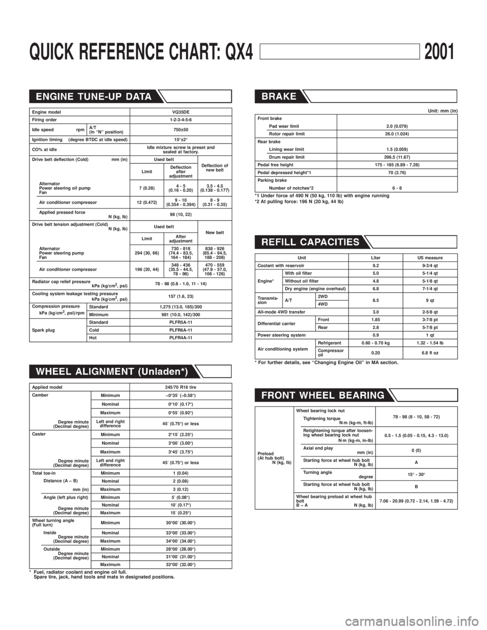
QUICK REFERENCE CHART: QX42001
Engine model VQ35DE
Firing order 1-2-3-4-5-6
Idle speed rpmA/T
(in ªNº position)750 50
Ignition timing (degree BTDC at idle speed) 15É 2É
CO% at idleIdle mixture screw is preset and
sealed at factory.
Drive belt deflection (Cold) mm (in) Used belt
Deflection of
new belt
LimitDeflection
after
adjustment
Alternator
Power steering oil pump
Fan7 (0.28)4-5
(0.16 - 0.20)3.5 - 4.5
(0.138 - 0.177)
Air conditioner compressor 12 (0.472)9-10
(0.354 - 0.394)8-9
(0.31 - 0.35)
Applied pressed force
N (kg, lb)98 (10, 22)
Drive belt tension adjustment (Cold)
N (kg, lb)Used belt
New belt
LimitAfter
adjustment
Alternator
Power steering pump
Fan294 (30, 66)730 - 818
(74.4 - 83.5,
164 - 184)838 - 926
(85.4 - 94.5,
188 - 208)
Air conditioner compressor 196 (20, 44)348 - 436
(35.5 - 44.5,
78 - 98)470 - 559
(47.9 - 57.0,
106 - 126)
Radiator cap relief pressure
kPa (kg/cm
2, psi)78 - 98 (0.8 - 1.0, 11 - 14)
Cooling system leakage testing pressure
kPa (kg/cm
2, psi)157 (1.6, 23)
Compression pressure
kPa (kg/cm
2, psi)/rpmStandard 1,275 (13.0, 185)/300
Minimum 981 (10.0, 142)/300
Spark plugStandard PLFR5A-11
Cold PLFR6A-11
Hot PLFR4A-11
Applied model 245/70 R16 tire
Camber
Degree minute
(Decimal degree)Minimum þ0É35¢(þ0.58É)
Nominal 0É10¢(0.17É)
Maximum 0É55¢(0.92É)
Left and right
difference45¢(0.75É) or less
Caster
Degree minute
(Decimal degree)Minimum 2É15¢(2.25É)
Nominal 3É00¢(3.00É)
Maximum 3É45¢(3.75É)
Left and right
difference45¢(0.75É) or less
Total toe-in Minimum 1 (0.04)
Distance (A þ B)
mm (in)Nominal 2 (0.08)
Maximum 3 (0.12)
Angle (left plus right)
Degree minute
(Decimal degree)Minimum 5¢(0.08É)
Nominal 10¢(0.17É)
Maximum 15¢(0.25É)
Wheel turning angle
(Full turn)Minimum 30É00¢(30.00É)
Inside
Degree minute
(Decimal degree)Nominal 33É00¢(33.00É)
Maximum 34É00¢(34.00É)
Outside
Degree minute
(Decimal degree)Minimum 28É00¢(28.00É)
Nominal 31É00¢(31.00É)
Maximum 32É00¢(32.00É)
* Fuel, radiator coolant and engine oil full.
Spare tire, jack, hand tools and mats in designated positions.
Unit: mm (in)Front brake
Pad wear limit 2.0 (0.079)
Rotor repair limit 26.0 (1.024)
Rear brake
Lining wear limit 1.5 (0.059)
Drum repair limit 296.5 (11.67)
Pedal free height 175 - 185 (6.89 - 7.28)
Pedal depressed height*1 70 (2.76)
Parking brake
Number of notches*2 6 - 8
*1 Under force of 490 N (50 kg, 110 lb) with engine running
*2 At pulling force: 196 N (20 kg, 44 lb)
Unit Liter US measure
Coolant with reservoir 9.2 9-3/4 qt
Engine*With oil filter 5.0 5-1/4 qt
Without oil filter 4.8 5-1/8 qt
Dry engine (engine overhaul) 6.8 7-1/4 qt
Transmis-
sionA/T2WD
8.5 9 qt
4WD
All-mode 4WD transfer 3.0 2-5/8 qt
Differential carrierFront 1.85 3-7/8 pt
Rear 2.8 5-7/8 pt
Power steering system 0.9 1 qt
Air conditioning systemRefrigerant 0.60 - 0.70 kg 1.32 - 1.54 lb
Compressor
oil0.20 6.8 fl oz
* For further details, see ªChanging Engine Oilº in MA section.
Preload
(At hub bolt)
N (kg, lb)Wheel bearing lock nut
78-98(8-10,58-72)
Tightening torque
N×m (kg-m, ft-lb)
Retightening torque after loosen-
ing wheel bearing lock nut
N×m (kg-m, in-lb)0.5 - 1.5 (0.05 - 0.15, 4.3 - 13.0)
Axial end play
mm (in)0 (0)
Starting force at wheel hub bolt
N (kg, lb)A
Turning angle
degree15É - 30É
Starting force at wheel hub bolt
N (kg, lb)B
Wheel bearing preload at wheel hub
bolt
B þ A N (kg, lb)7.06 - 20.99 (0.72 - 2.14, 1.59 - 4.72)
Page 1746 of 2395
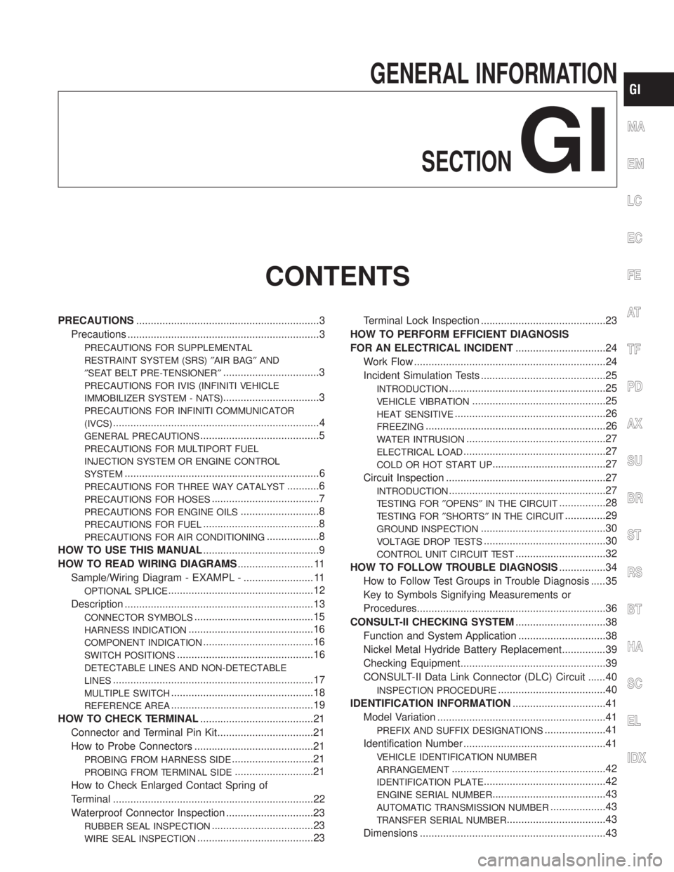
GENERAL INFORMATION
SECTION
GI
CONTENTS
PRECAUTIONS...............................................................3
Precautions ..................................................................3
PRECAUTIONS FOR SUPPLEMENTAL
RESTRAINT SYSTEM (SRS)²AIR BAG²AND
²SEAT BELT PRE-TENSIONER²
.................................3
PRECAUTIONS FOR IVIS (INFINITI VEHICLE
IMMOBILIZER SYSTEM - NATS)
.................................3
PRECAUTIONS FOR INFINITI COMMUNICATOR
(IVCS)
.......................................................................4
GENERAL PRECAUTIONS.........................................5
PRECAUTIONS FOR MULTIPORT FUEL
INJECTION SYSTEM OR ENGINE CONTROL
SYSTEM
...................................................................6
PRECAUTIONS FOR THREE WAY CATALYST...........6
PRECAUTIONS FOR HOSES.....................................7
PRECAUTIONS FOR ENGINE OILS...........................8
PRECAUTIONS FOR FUEL........................................8
PRECAUTIONS FOR AIR CONDITIONING..................8
HOW TO USE THIS MANUAL........................................9
HOW TO READ WIRING DIAGRAMS.......................... 11
Sample/Wiring Diagram - EXAMPL - ........................ 11
OPTIONAL SPLICE..................................................12
Description .................................................................13
CONNECTOR SYMBOLS.........................................15
HARNESS INDICATION...........................................16
COMPONENT INDICATION......................................16
SWITCH POSITIONS...............................................16
DETECTABLE LINES AND NON-DETECTABLE
LINES
.....................................................................17
MULTIPLE SWITCH.................................................18
REFERENCE AREA.................................................19
HOW TO CHECK TERMINAL.......................................21
Connector and Terminal Pin Kit.................................21
How to Probe Connectors .........................................21
PROBING FROM HARNESS SIDE............................21
PROBING FROM TERMINAL SIDE...........................21
How to Check Enlarged Contact Spring of
Terminal .....................................................................22
Waterproof Connector Inspection ..............................23
RUBBER SEAL INSPECTION...................................23
WIRE SEAL INSPECTION........................................23Terminal Lock Inspection ...........................................23
HOW TO PERFORM EFFICIENT DIAGNOSIS
FOR AN ELECTRICAL INCIDENT...............................24
Work Flow ..................................................................24
Incident Simulation Tests ...........................................25
INTRODUCTION......................................................25
VEHICLE VIBRATION..............................................25
HEAT SENSITIVE....................................................26
FREEZING..............................................................26
WATER INTRUSION................................................27
ELECTRICAL LOAD.................................................27
COLD OR HOT START UP.......................................27
Circuit Inspection .......................................................27
INTRODUCTION......................................................27
TESTING FOR²OPENS²IN THE CIRCUIT................28
TESTING FOR²SHORTS²IN THE CIRCUIT..............29
GROUND INSPECTION...........................................30
VOLTAGE DROP TESTS..........................................30
CONTROL UNIT CIRCUIT TEST...............................32
HOW TO FOLLOW TROUBLE DIAGNOSIS................34
How to Follow Test Groups in Trouble Diagnosis .....35
Key to Symbols Signifying Measurements or
Procedures.................................................................36
CONSULT-II CHECKING SYSTEM...............................38
Function and System Application ..............................38
Nickel Metal Hydride Battery Replacement...............39
Checking Equipment..................................................39
CONSULT-II Data Link Connector (DLC) Circuit ......40
INSPECTION PROCEDURE.....................................40
IDENTIFICATION INFORMATION................................41
Model Variation ..........................................................41
PREFIX AND SUFFIX DESIGNATIONS.....................41
Identification Number .................................................41
VEHICLE IDENTIFICATION NUMBER
ARRANGEMENT
.....................................................42
IDENTIFICATION PLATE..........................................42
ENGINE SERIAL NUMBER.......................................43
AUTOMATIC TRANSMISSION NUMBER...................43
TRANSFER SERIAL NUMBER..................................43
Dimensions ................................................................43
MA
EM
LC
EC
FE
AT
TF
PD
AX
SU
BR
ST
RS
BT
HA
SC
EL
IDX