oil INFINITI QX4 2001 Factory Workshop Manual
[x] Cancel search | Manufacturer: INFINITI, Model Year: 2001, Model line: QX4, Model: INFINITI QX4 2001Pages: 2395, PDF Size: 43.2 MB
Page 294 of 2395

SAT999A
13. Remove converter housing from transmission case.
IBe careful not to scratch converter housing.
SAT995A
14. Remove O-ring from input shaft.
SAT027B
15. Remove oil pump assembly.
a. Attach Tool to oil pump assembly and extract it evenly from
transmission case.
SAT028B
b. Remove O-ring from oil pump assembly.
c. Remove traces of sealant from oil pump housing.
IBe careful not to scratch pump housing.
SAT108B
d. Remove needle bearing and thrust washer from oil pump
assembly.
GI
MA
EM
LC
EC
FE
TF
PD
AX
SU
BR
ST
RS
BT
HA
SC
EL
IDX
DISASSEMBLY
AT-289
Page 295 of 2395
SAT988A
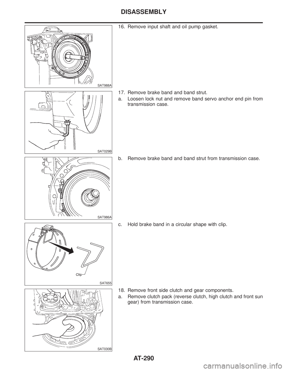
16. Remove input shaft and oil pump gasket.
SAT029B
17. Remove brake band and band strut.
a. Loosen lock nut and remove band servo anchor end pin from
transmission case.
SAT986A
b. Remove brake band and band strut from transmission case.
SAT655
c. Hold brake band in a circular shape with clip.
SAT030B
18. Remove front side clutch and gear components.
a. Remove clutch pack (reverse clutch, high clutch and front sun
gear) from transmission case.
DISASSEMBLY
AT-290
Page 297 of 2395

SAT755I
20. Remove adapter case (4WD model only).
a. Remove adapter case from transmission case.
b. Remove adapter case gasket from transmission case.
SAT756I
c. Remove oil seal from adapter case.
IBe careful not to scratch adapter case.
IDo not remove oil seal unless it is to be replaced.
SAT556J
21. Remove revolution sensor from rear extension or adapter
case.
a. Remove O-ring from revolution sensor.
SAT960A
22. Remove output shaft and parking gear (4WD model only).
a. Remove rear snap ring from output shaft.
SAT957A
b. Slowly push output shaft all the way forward.
IDo not use excessive force.
c. Remove snap ring from output shaft.
DISASSEMBLY
AT-292
Page 300 of 2395
SAT039B
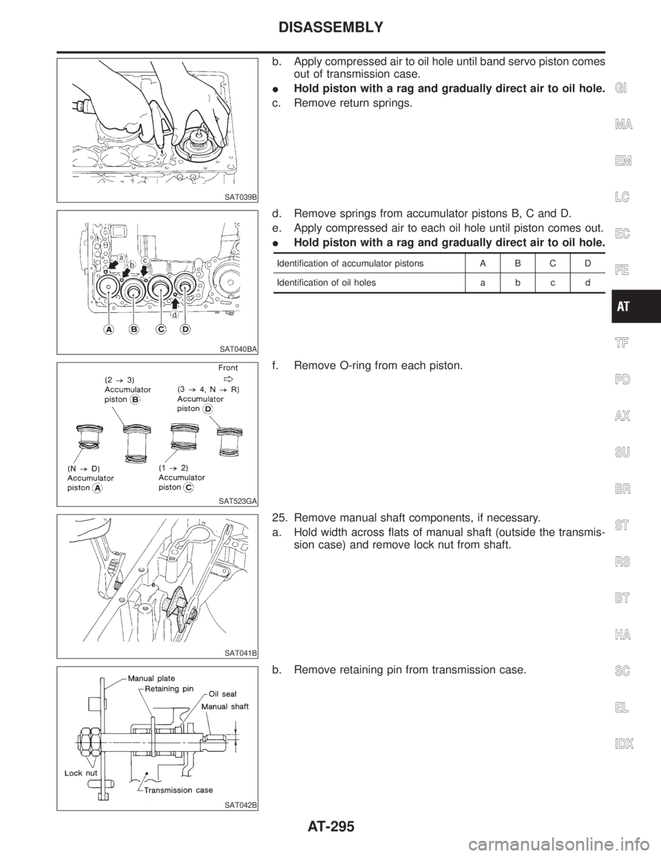
b. Apply compressed air to oil hole until band servo piston comes
out of transmission case.
IHold piston with a rag and gradually direct air to oil hole.
c. Remove return springs.
SAT040BA
d. Remove springs from accumulator pistons B, C and D.
e. Apply compressed air to each oil hole until piston comes out.
IHold piston with a rag and gradually direct air to oil hole.
Identification of accumulator pistons A B C D
Identification of oil holes a b c d
SAT523GA
f. Remove O-ring from each piston.
SAT041B
25. Remove manual shaft components, if necessary.
a. Hold width across flats of manual shaft (outside the transmis-
sion case) and remove lock nut from shaft.
SAT042B
b. Remove retaining pin from transmission case.
GI
MA
EM
LC
EC
FE
TF
PD
AX
SU
BR
ST
RS
BT
HA
SC
EL
IDX
DISASSEMBLY
AT-295
Page 301 of 2395
SAT935A
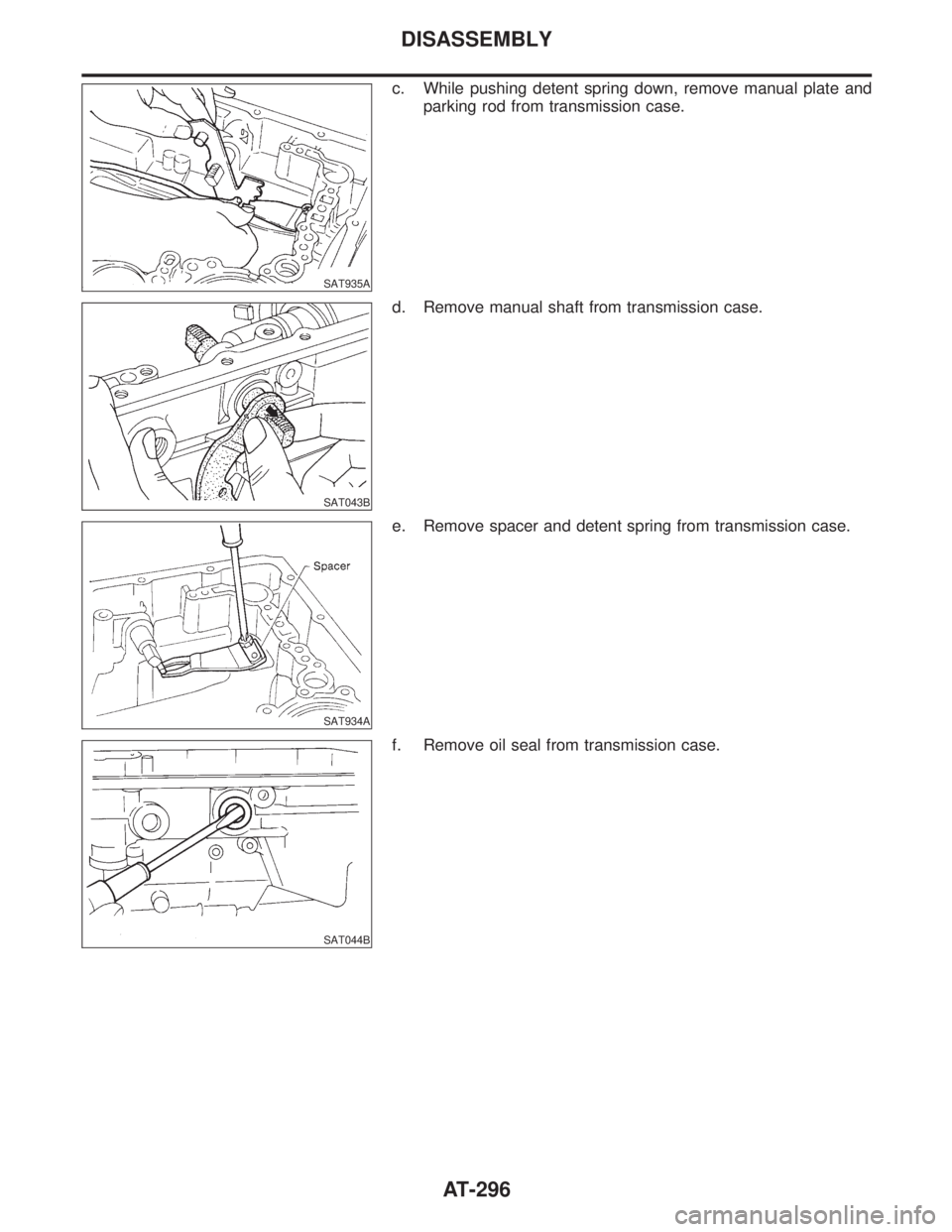
c. While pushing detent spring down, remove manual plate and
parking rod from transmission case.
SAT043B
d. Remove manual shaft from transmission case.
SAT934A
e. Remove spacer and detent spring from transmission case.
SAT044B
f. Remove oil seal from transmission case.
DISASSEMBLY
AT-296
Page 302 of 2395

Oil Pump
COMPONENTSNBAT0112
SAT648AB
SAT649A
DISASSEMBLYNBAT01131. Loosen bolts in numerical order and remove oil pump cover.
SAT650A
2. Remove rotor, vane rings and vanes.
IInscribe a mark on back of rotor for identification of fore-
aft direction when reassembling rotor. Then remove rotor.
SAT651A
3. While pushing on cam ring remove pivot pin.
IBe careful not to scratch oil pump housing.
GI
MA
EM
LC
EC
FE
TF
PD
AX
SU
BR
ST
RS
BT
HA
SC
EL
IDX
REPAIR FOR COMPONENT PARTS
Oil Pump
AT-297
Page 303 of 2395

SAT652A
4. While holding cam ring and spring lift out cam ring spring.
IBe careful not to damage oil pump housing.
IHold cam ring spring to prevent it from jumping.
SAT653A
5. Remove cam ring and cam ring spring from oil pump housing.
SAT654A
6. Remove pivot pin from control piston and remove control pis-
ton assembly.
SAT655A
7. Remove oil seal from oil pump housing.
IBe careful not to scratch oil pump housing.
SAT656A
INSPECTIONNBAT0114Oil Pump Cover, Rotor, Vanes, Control Piston, Side
Seals, Cam Ring and Friction Ring
NBAT0114S01ICheck for wear or damage.
REPAIR FOR COMPONENT PARTS
Oil Pump (Cont'd)
AT-298
Page 304 of 2395
SAT657A
SAT658A
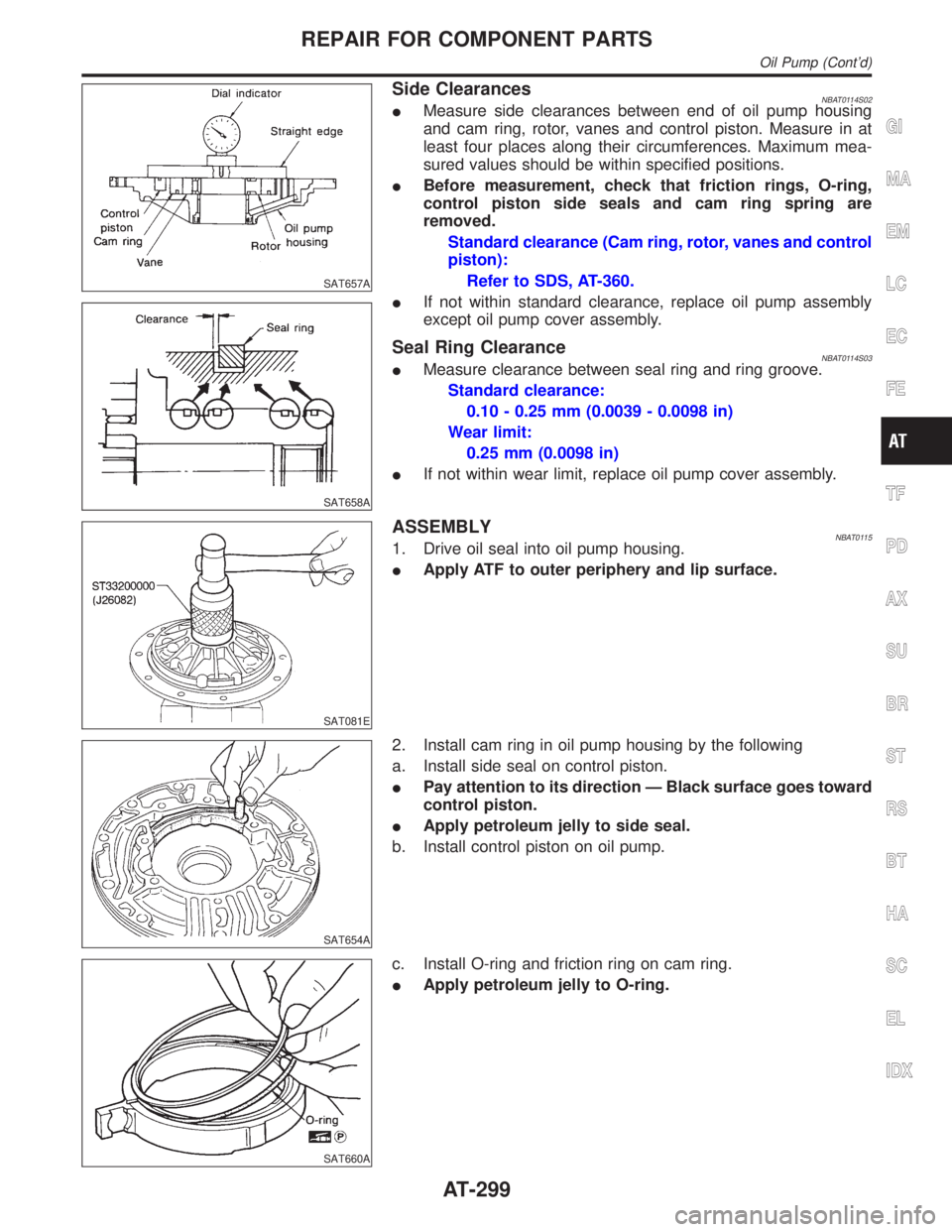
Side ClearancesNBAT0114S02IMeasure side clearances between end of oil pump housing
and cam ring, rotor, vanes and control piston. Measure in at
least four places along their circumferences. Maximum mea-
sured values should be within specified positions.
IBefore measurement, check that friction rings, O-ring,
control piston side seals and cam ring spring are
removed.
Standard clearance (Cam ring, rotor, vanes and control
piston):
Refer to SDS, AT-360.
IIf not within standard clearance, replace oil pump assembly
except oil pump cover assembly.
Seal Ring ClearanceNBAT0114S03IMeasure clearance between seal ring and ring groove.
Standard clearance:
0.10 - 0.25 mm (0.0039 - 0.0098 in)
Wear limit:
0.25 mm (0.0098 in)
IIf not within wear limit, replace oil pump cover assembly.
SAT081E
ASSEMBLYNBAT01151. Drive oil seal into oil pump housing.
IApply ATF to outer periphery and lip surface.
SAT654A
2. Install cam ring in oil pump housing by the following
a. Install side seal on control piston.
IPay attention to its direction Ð Black surface goes toward
control piston.
IApply petroleum jelly to side seal.
b. Install control piston on oil pump.
SAT660A
c. Install O-ring and friction ring on cam ring.
IApply petroleum jelly to O-ring.
GI
MA
EM
LC
EC
FE
TF
PD
AX
SU
BR
ST
RS
BT
HA
SC
EL
IDX
REPAIR FOR COMPONENT PARTS
Oil Pump (Cont'd)
AT-299
Page 305 of 2395

SAT661A
d. Assemble cam ring, cam ring spring and spring seat. Install
spring by pushing it against pump housing.
SAT651A
e. While pushing on cam ring install pivot pin.
SAT662A
3. Install rotor, vanes and vane rings.
IPay attention to direction of rotor.
SAT649A
4. Install oil pump housing and oil pump cover.
a. Wrap masking tape around splines of oil pump cover assem-
bly to protect seal. Position oil pump cover assembly in oil
pump housing assembly, then remove masking tape.
b. Tighten bolts in a criss-cross pattern.
SAT663A
5. Install new seal rings carefully after packing ring grooves with
petroleum jelly. Press rings down into jelly to a close fit.
ISeal rings come in two different diameters. Check fit care-
fully in each groove.
Small dia. seal ring:
No mark
Large dia. seal ring:
Yellow mark in area shown by arrow
IDo not spread gap of seal ring excessively while install-
ing. It may deform ring.
REPAIR FOR COMPONENT PARTS
Oil Pump (Cont'd)
AT-300
Page 308 of 2395
SAT671A
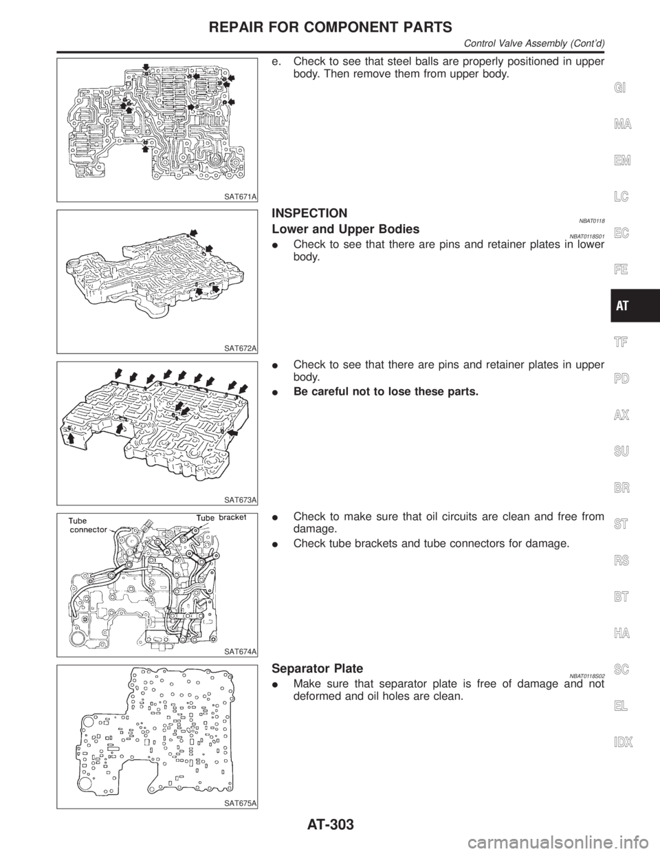
e. Check to see that steel balls are properly positioned in upper
body. Then remove them from upper body.
SAT672A
INSPECTIONNBAT0118Lower and Upper BodiesNBAT0118S01ICheck to see that there are pins and retainer plates in lower
body.
SAT673A
ICheck to see that there are pins and retainer plates in upper
body.
IBe careful not to lose these parts.
SAT674A
ICheck to make sure that oil circuits are clean and free from
damage.
ICheck tube brackets and tube connectors for damage.
SAT675A
Separator PlateNBAT0118S02IMake sure that separator plate is free of damage and not
deformed and oil holes are clean.
GI
MA
EM
LC
EC
FE
TF
PD
AX
SU
BR
ST
RS
BT
HA
SC
EL
IDX
REPAIR FOR COMPONENT PARTS
Control Valve Assembly (Cont'd)
AT-303