IDX INFINITI QX4 2001 Factory Repair Manual
[x] Cancel search | Manufacturer: INFINITI, Model Year: 2001, Model line: QX4, Model: INFINITI QX4 2001Pages: 2395, PDF Size: 43.2 MB
Page 126 of 2395

SAT014K
SAT971J
SAT021J
DIAGNOSTIC TROUBLE CODE (DTC) CONFIRMATION
PROCEDURE
NBAT0039S01CAUTION:
IAlways drive vehicle at a safe speed.
IBe careful not to rev engine into the red zone on the
tachometer.
NOTE:
If ªDIAGNOSTIC TROUBLE CODE CONFIRMATION PROCE-
DUREº has been previously conducted, always turn ignition
switch ªOFFº and wait at least 5 seconds before conducting
the next test.
TESTING CONDITIONS:
Always drive vehicle on a level road to improve the accuracy of
test.
After the repair, perform the following procedure to confirm the
malfunction is eliminated.
With CONSULT-II
1) Start engine and select ªDATA MONITORº mode for ªA/Tº with
CONSULT-II.
2) Make sure that output voltage of A/T fluid temperature sensor
is within the range below.
FLUID TEMP SEN: 0.4 - 1.5V
If out of range, drive the vehicle to decrease the voltage (warm
up the fluid) or stop engine to increase the voltage (cool down
the fluid).
3) Select ª1ST GR FNCTN P0731º of ªDTC WORK SUPPORTº
mode for ªA/Tº with CONSULT-II and touch ªSTARTº.
4) Accelerate vehicle to 10 to 20 km/h (6 to 12 MPH) under the
following condition and release the accelerator pedal com-
pletely.
THROTTLE POSI: Less than 1.0/8 (at all times during step
4)
Selector lever: D position (OD ªONº)
ICheck that ªGEARº shows ª2º after releasing pedal.
5) Depress accelerator pedal to WOT (more than 7.0/8 of
ªTHROTTLE POSIº) quickly from a speed of 10 to 20 km/h (6
to 12 MPH) until ªTESTINGº changes to ªSTOP VEHICLEº or
ªCOMPLETEDº. (It will take approximately 3 seconds.)
If the check result NG appears on CONSULT-II screen, go to
ªDIAGNOSTIC PROCEDUREº, AT-124.
If ªSTOP VEHICLEº appears on CONSULT-II screen, go to the
following step.
ICheck that ªGEARº shows ª1º when depressing accelera-
tor pedal to WOT.
IIf ªTESTINGº does not appear on CONSULT-II for a long
time, select ªSELF-DIAG RESULTSº for ªENGINEº. In case
a 1st trip DTC other than P0731 is shown, refer to appli-
cable ªTROUBLE DIAGNOSIS FOR DTCº.
6) Stop vehicle.
7) Follow the instruction displayed. (Check for normal shifting
referring to the table below.)
Vehicle conditionGear on actual transmission shift pattern when
screen is changed to 1,2,3,4
No malfunction exists 1,2,3,4
GI
MA
EM
LC
EC
FE
TF
PD
AX
SU
BR
ST
RS
BT
HA
SC
EL
IDX
DTC P0731 IMPROPER SHIFTING TO 1ST GEAR POSITION
Description (Cont'd)
AT-121
Page 128 of 2395

Wiring Diagram Ð AT Ð 1STNBAT0190
MAT731A
GI
MA
EM
LC
EC
FE
TF
PD
AX
SU
BR
ST
RS
BT
HA
SC
EL
IDX
DTC P0731 IMPROPER SHIFTING TO 1ST GEAR POSITION
Wiring Diagram Ð AT Ð 1ST
AT-123
Page 130 of 2395

SAT649I
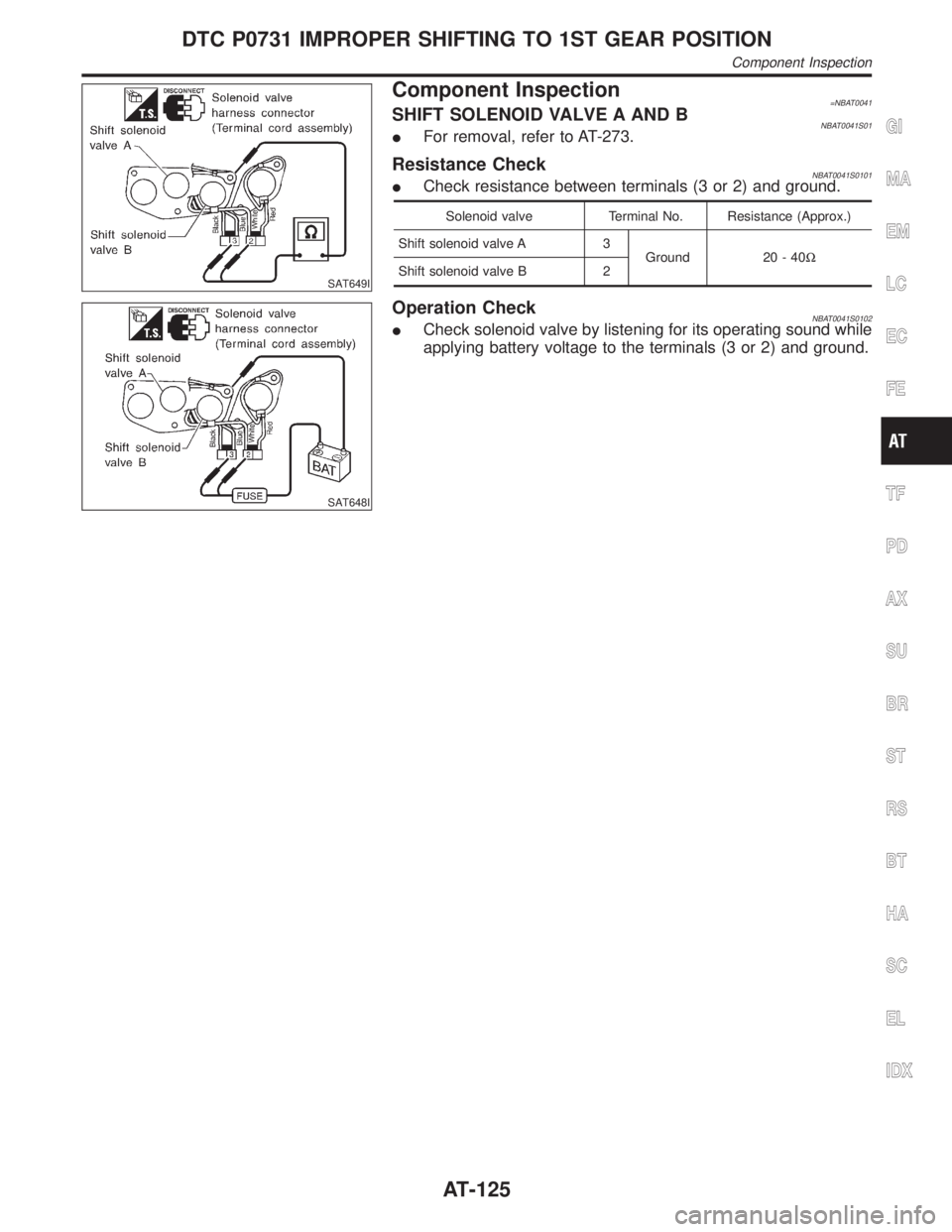
Component Inspection=NBAT0041SHIFT SOLENOID VALVE A AND BNBAT0041S01IFor removal, refer to AT-273.
Resistance CheckNBAT0041S0101ICheck resistance between terminals (3 or 2) and ground.
Solenoid valve Terminal No. Resistance (Approx.)
Shift solenoid valve A 3
Ground 20 - 40W
Shift solenoid valve B 2
SAT648I
Operation CheckNBAT0041S0102ICheck solenoid valve by listening for its operating sound while
applying battery voltage to the terminals (3 or 2) and ground.
GI
MA
EM
LC
EC
FE
TF
PD
AX
SU
BR
ST
RS
BT
HA
SC
EL
IDX
DTC P0731 IMPROPER SHIFTING TO 1ST GEAR POSITION
Component Inspection
AT-125
Page 132 of 2395

SAT014K
SAT971J
SAT021J
DIAGNOSTIC TROUBLE CODE (DTC) CONFIRMATION
PROCEDURE
NBAT0042S01CAUTION:
IAlways drive vehicle at a safe speed.
IBe careful not to rev engine into the red zone on the
tachometer.
NOTE:
If ªDIAGNOSTIC TROUBLE CODE CONFIRMATION PROCE-
DUREº has been previously conducted, always turn ignition
switch ªOFFº and wait at least 5 seconds before conducting
the next test.
TESTING CONDITIONS:
Always drive vehicle on a level road to improve the accuracy
of test.
After the repair, perform the following procedure to confirm the
malfunction is eliminated.
With CONSULT-II
1) Start engine and select ªDATA MONITORº mode for ªA/Tº with
CONSULT-II.
2) Make sure that output voltage of A/T fluid temperature sensor
is within the range below.
FLUID TEMP SEN: 0.4 - 1.5V
If out of range, drive the vehicle to decrease the voltage (warm
up the fluid) or stop engine to increase the voltage (cool down
the fluid).
3) Select ª2ND GR FNCTN P0732º of ªDTC WORK SUPPORTº
mode for ªA/Tº with CONSULT-II and touch ªSTARTº.
4) Accelerate vehicle to 25 to 30 km/h (16 to 19 MPH) under the
following condition and release the accelerator pedal com-
pletely.
THROTTLE POSI: Less than 1.0/8 (at all times during step
4)
Selector lever: D position (OD ªONº)
ICheck that ªGEARº shows ª3º or ª4º after releasing pedal.
5) Depress accelerator pedal to WOT (more than 7.0/8 of
ªTHROTTLE POSIº) quickly from a speed of 25 to 30 km/h (16
to 19 MPH) until ªTESTINGº changes to ªSTOP VEHICLEº or
ªCOMPLETEDº. (It will take approximately 3 seconds.)
If the check result NG appears on CONSULT-II screen, go to
ªDIAGNOSTIC PROCEDUREº, AT-130.
If ªSTOP VEHICLEº appears on CONSULT-II screen, go to
following step.
ICheck that ªGEARº shows ª2º when depressing accelera-
tor pedal to WOT.
IIf ªTESTINGº does not appear on CONSULT-II for a long
time, select ªSELF-DIAG RESULTSº for ªENGINEº. In case
a 1st trip DTC other than P0732 is shown, refer to appli-
cable ªTROUBLE DIAGNOSIS FOR DTCº.
6) Stop vehicle.
7) Follow the instruction displayed. (Check for normal shifting
referring to the table below.)
Vehicle conditionGear on actual transmission shift pattern when
screen is changed to 1,2,3,4
No malfunction exists 1,2,3,4
Malfunction for P0732 exists. 4,3,3,4
GI
MA
EM
LC
EC
FE
TF
PD
AX
SU
BR
ST
RS
BT
HA
SC
EL
IDX
DTC P0732 IMPROPER SHIFTING TO 2ND GEAR POSITION
Description (Cont'd)
AT-127
Page 134 of 2395

Wiring Diagram Ð AT Ð 2NDNBAT0191
MAT732A
GI
MA
EM
LC
EC
FE
TF
PD
AX
SU
BR
ST
RS
BT
HA
SC
EL
IDX
DTC P0732 IMPROPER SHIFTING TO 2ND GEAR POSITION
Wiring Diagram Ð AT Ð 2ND
AT-129
Page 136 of 2395

SAT651I
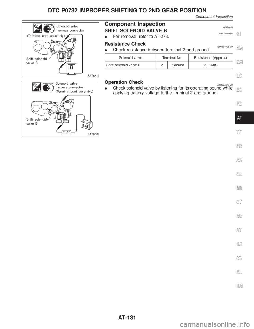
Component InspectionNBAT0044SHIFT SOLENOID VALVE BNBAT0044S01IFor removal, refer to AT-273.
Resistance CheckNBAT0044S0101ICheck resistance between terminal 2 and ground.
Solenoid valve Terminal No. Resistance (Approx.)
Shift solenoid valve B 2 Ground 20 - 40W
SAT650I
Operation CheckNBAT0044S0102ICheck solenoid valve by listening for its operating sound while
applying battery voltage to the terminal 2 and ground.
GI
MA
EM
LC
EC
FE
TF
PD
AX
SU
BR
ST
RS
BT
HA
SC
EL
IDX
DTC P0732 IMPROPER SHIFTING TO 2ND GEAR POSITION
Component Inspection
AT-131
Page 138 of 2395

SAT014K
SAT971J
SAT021J
DIAGNOSTIC TROUBLE CODE (DTC) CONFIRMATION
PROCEDURE
NBAT0045S01CAUTION:
IAlways drive vehicle at a safe speed.
IBe careful not to rev engine into the red zone on the
tachometer.
NOTE:
If ªDIAGNOSTIC TROUBLE CODE CONFIRMATION PROCE-
DUREº has been previously conducted, always turn ignition
switch ªOFFº and wait at least 5 seconds before conducting
the next test.
TESTING CONDITIONS:
Always drive vehicle on a level road to improve the accuracy
of test.
After the repair, perform the following procedure to confirm the
malfunction is eliminated.
With CONSULT-II
1) Start engine and select ªDATA MONITORº mode for ªA/Tº with
CONSULT-II.
2) Make sure that output voltage of A/T fluid temperature sensor
is within the range below.
FLUID TEMP SEN: 0.4 - 1.5V
If out of range, drive the vehicle to decrease the voltage (warm
up the fluid) or stop engine to increase the voltage (cool down
the fluid).
3) Select ª3RD GR FNCTN P0733º of ªDTC WORK SUPPORTº
mode for ªA/Tº with CONSULT-II and touch ªSTARTº.
4) Accelerate vehicle to 35 to 45 km/h (22 to 28 MPH) under the
following condition and release the accelerator pedal com-
pletely.
THROTTLE POSI: Less than 1.0/8 (at all times during step
4)
Selector lever: D position (OD ªONº)
ICheck that ªGEARº shows ª4º after releasing pedal.
5) Depress accelerator pedal steadily with 3.5/8 - 4.5/8 of
ªTHROTTLE POSIº from a speed of 35 to 45 km/h (22 to 28
MPH) until ªTESTINGº changes to ªSTOP VEHICLEº or ªCOM-
PLETEDº. (It will take approximately 3 seconds.)
If the check result NG appears on CONSULT-II screen, go to
ªDIAGNOSTIC PROCEDUREº, AT-136.
If ªSTOP VEHICLEº appears on CONSULT-II screen, go to
following step.
ICheck that ªGEARº shows ª3º when depressing accelera-
tor pedal with 3.5/8 - 4.5/8 of ªTHROTTLE POSIº.
IIf ªTESTINGº does not appear on CONSULT-II for a long
time, select ªSELF-DIAG RESULTSº for ªENGINEº. In case
a 1st trip DTC other than P0733 is shown, refer to appli-
cable ªTROUBLE DIAGNOSIS FOR DTCº.
6) Stop vehicle.
7) Follow the instruction displayed. (Check for normal shifting
referring to the table below.)
Vehicle conditionGear on actual transmission shift pattern
when screen is changed to 1,2,3,4
No malfunction exists. 1,2,3,4
Malfunction for P0733 exists. 1,1,4,4
GI
MA
EM
LC
EC
FE
TF
PD
AX
SU
BR
ST
RS
BT
HA
SC
EL
IDX
DTC P0733 IMPROPER SHIFTING TO 3RD GEAR POSITION
Description (Cont'd)
AT-133
Page 140 of 2395

Wiring Diagram Ð AT Ð 3RDNBAT0192
MAT733A
GI
MA
EM
LC
EC
FE
TF
PD
AX
SU
BR
ST
RS
BT
HA
SC
EL
IDX
DTC P0733 IMPROPER SHIFTING TO 3RD GEAR POSITION
Wiring Diagram Ð AT Ð 3RD
AT-135
Page 142 of 2395

SAT654I
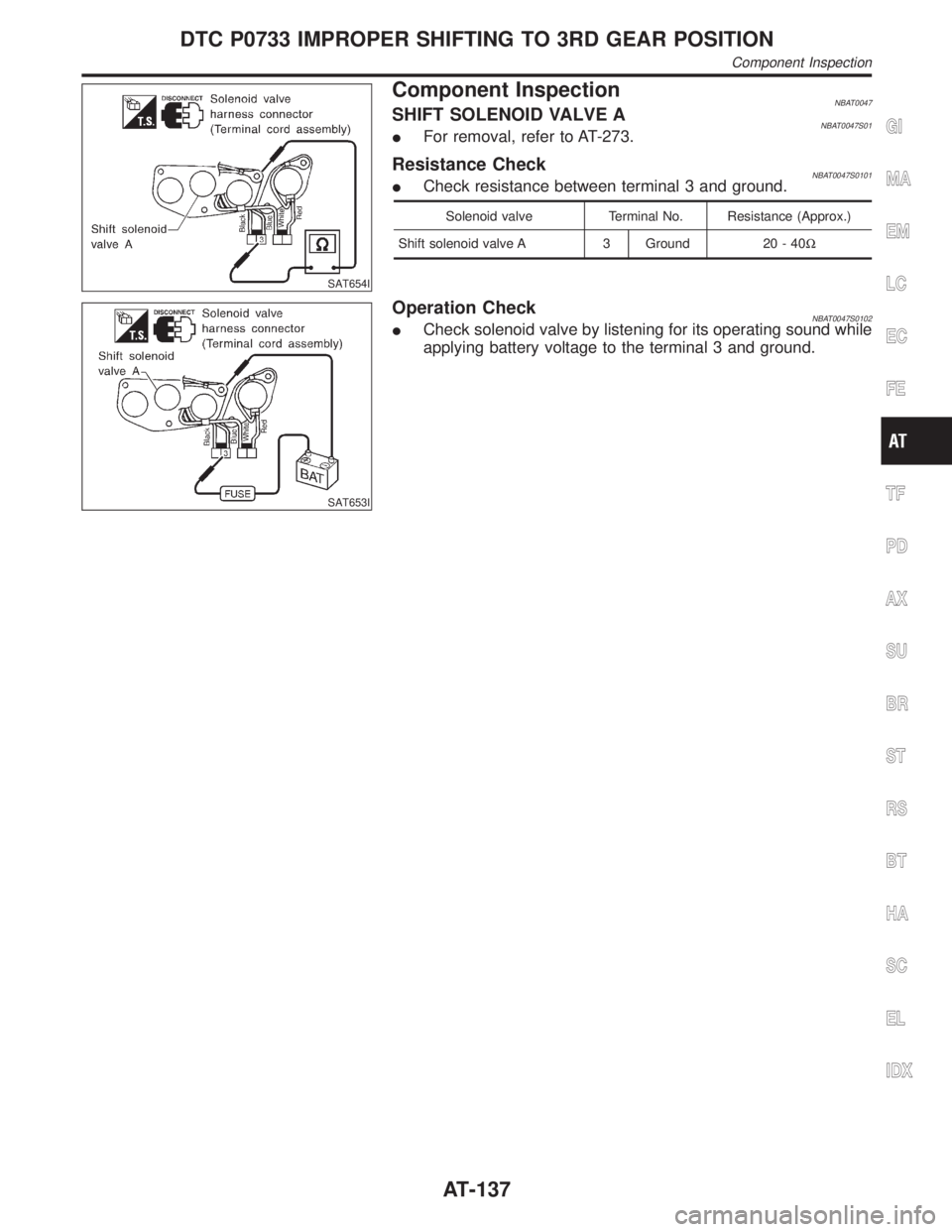
Component InspectionNBAT0047SHIFT SOLENOID VALVE ANBAT0047S01IFor removal, refer to AT-273.
Resistance CheckNBAT0047S0101ICheck resistance between terminal 3 and ground.
Solenoid valve Terminal No. Resistance (Approx.)
Shift solenoid valve A 3 Ground 20 - 40W
SAT653I
Operation CheckNBAT0047S0102ICheck solenoid valve by listening for its operating sound while
applying battery voltage to the terminal 3 and ground.
GI
MA
EM
LC
EC
FE
TF
PD
AX
SU
BR
ST
RS
BT
HA
SC
EL
IDX
DTC P0733 IMPROPER SHIFTING TO 3RD GEAR POSITION
Component Inspection
AT-137
Page 144 of 2395

ON BOARD DIAGNOSIS LOGIC=NBAT0048S03This diagnosis monitors actual gear position by checking the torque
converter slip ratio calculated by TCM as follows:
Torque converter slip ratio = A x C/B
A: Output shaft revolution signal from revolution sensor
B: Engine speed signal from ECM
C: Gear ratio determined as gear position which TCM supposes
If the actual gear position is much lower than the position (4th)
supposed by TCM, the slip ratio will be much less than normal. In
case the ratio does not reach the specified value, TCM judges this
diagnosis malfunction.
This malfunction will be caused when shift solenoid valve B is stuck
closed.
Gear position supposed by TCM1234
In case of gear position with no malfunctions1234
In case of gear position with shift solenoid valve B
stuck closed1221*
*: P0734 is detected.
Diagnostic trouble code Malfunction is detected when ... Check item (Possible cause)
: A/T 4TH GR FNCTN
A/T cannot be shifted to the 4th gear
position even if electrical circuit is good.IShift solenoid valve A
IShift solenoid valve B
ILine pressure solenoid valve
IEach clutch
IHydraulic control circuit
: P0734
GI
MA
EM
LC
EC
FE
TF
PD
AX
SU
BR
ST
RS
BT
HA
SC
EL
IDX
DTC P0734 IMPROPER SHIFTING TO 4TH GEAR POSITION
Description (Cont'd)
AT-139