service indicator INFINITI QX56 2007 Factory Owners Manual
[x] Cancel search | Manufacturer: INFINITI, Model Year: 2007, Model line: QX56, Model: INFINITI QX56 2007Pages: 3061, PDF Size: 64.56 MB
Page 1494 of 3061

DTC P0455 EVAP CONTROL SYSTEM
EC-411
< SERVICE INFORMATION >
C
D
E
F
G
H
I
J
K
L
MA
EC
N
P O
8.INSTALL THE PRESSURE PUMP
To locate the EVAP leak, install EVAP service port adapter and pres-
sure pump to EVAP service port securely.
NOTE:
Improper installation of the EVAP service port adapter to the
EVAP service port may cause leaking.
With CONSULT-II>>GO TO 9.
Without CONSULT-II>>GO TO 10.
9.CHECK FOR EVAP LEAK
With CONSULT-II
1. Turn ignition switch ON.
2. Select “EVAP SYSTEM CLOSE” of “WORK SUPPORT” mode
with CONSULT-II.
3. Touch “START” and apply pressure into the EVAP line until the
pressure indicator reaches the middle of the bar graph.
CAUTION:
• Do not use compressed air or a high pressure pump.
• Do not exceed 4.12 kPa (0.042 kg/cm
2, 0.6 psi) of pressure
in the system.
4. Using EVAP leak detector, locate the EVAP leak. For the leak
detector, refer to the instruction manual for more details.
Refer to EC-33, "
Description".
OK or NG
OK >> GO TO 11.
NG >> Repair or replace.
10.CHECK FOR EVAP LEAK
Without CONSULT-II
BBIA0366E
SEF916U
PEF917U
SEF200U
Page 1501 of 3061

EC-418
< SERVICE INFORMATION >
DTC P0456 EVAP CONTROL SYSTEM
3.CHECK FUEL FILLER CAP FUNCTION
Check for air releasing sound while opening the fuel filler cap.
OK or NG
OK >> GO TO 5.
NG >> GO TO 4.
4.CHECK FUEL TANK VACUUM RELIEF VALVE
Refer to EC-35, "
Component Inspection" .
OK or NG
OK >> GO TO 5.
NG >> Replace fuel filler cap with a genuine one.
5.INSTALL THE PRESSURE PUMP
To locate the EVAP leak, install EVAP service port adapter and pres-
sure pump to EVAP service port securely.
NOTE:
Improper installation of the EVAP service port adapter to the
EVAP service port may cause leaking.
With CONSULT-II>>GO TO 6.
Without CONSULT-II>>GO TO 7.
6.CHECK FOR EVAP LEAK
With CONSULT-II
1. Turn ignition switch ON.
2. Select “EVAP SYSTEM CLOSE” of “WORK SUPPORT” mode with CONSULT-II.
3. Touch “START” and apply pressure into the EVAP line until the
pressure indicator reaches the middle of the bar graph.
CAUTION:
• Do not use compressed air or a high pressure pump.
• Do not exceed 4.12 kPa (0.042 kg/cm
2 , 0.6 psi) of pres-
sure in the system.
BBIA0366E
SEF916U
PEF917U
Page 1612 of 3061

DTC P1572 ASCD BRAKE SWITCH
EC-529
< SERVICE INFORMATION >
C
D
E
F
G
H
I
J
K
L
MA
EC
N
P O
TESTING CONDITION:
Steps 4 and 5 may be conducted with the drive wheels lifted in the shop or by driving the vehicle. If a
road test is expected to be easier, it is unnecessary to lift the vehicle.
WITH CONSULT-II
1. Start engine (VDC switch OFF).
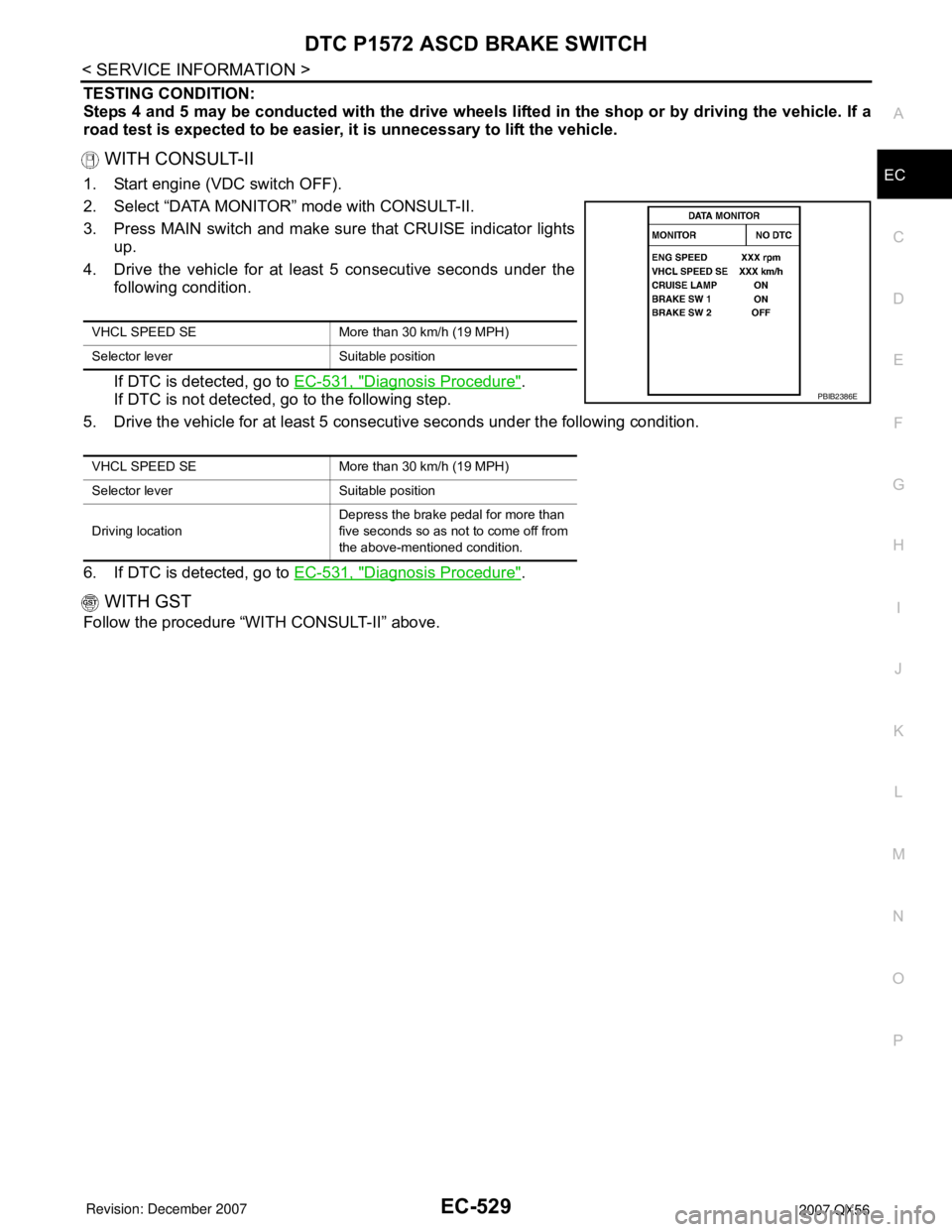
2. Select “DATA MONITOR” mode with CONSULT-II.
3. Press MAIN switch and make sure that CRUISE indicator lights
up.
4. Drive the vehicle for at least 5 consecutive seconds under the
following condition.
If DTC is detected, go to EC-531, "
Diagnosis Procedure".
If DTC is not detected, go to the following step.
5. Drive the vehicle for at least 5 consecutive seconds under the following condition.
6. If DTC is detected, go to EC-531, "
Diagnosis Procedure".
WITH GST
Follow the procedure “WITH CONSULT-II” above.
VHCL SPEED SE More than 30 km/h (19 MPH)
Selector lever Suitable position
VHCL SPEED SE More than 30 km/h (19 MPH)
Selector lever Suitable position
Driving locationDepress the brake pedal for more than
five seconds so as not to come off from
the above-mentioned condition.
PBIB2386E
Page 1686 of 3061

ASCD INDICATOR
EC-603
< SERVICE INFORMATION >
C
D
E
F
G
H
I
J
K
L
MA
EC
N
P O
ASCD INDICATOR
Component DescriptionINFOID:0000000003532153
ASCD indicator lamp illuminates to indicate ASCD operation status. Lamp has two indicators, CRUISE and
SET, and is integrated in combination meter.
CRUISE indicator illuminates when MAIN switch on ASCD steering switch is turned ON to indicate that ASCD
system is ready for operation.
SET indicator illuminates when following conditions are met.
• CRUISE indicator is illuminated.
• SET/COAST switch on ASCD steering switch is turned ON while vehicle speed is within the range of ASCD
setting.
SET indicator remains lit during ASCD control.
Refer to EC-30
for the ASCD function.
CONSULT-II Reference Value in Data Monitor ModeINFOID:0000000003532154
Specification data are reference value.
MONITOR ITEM CONDITION SPECIFICATION
CRUISE LAMP • Ignition switch: ON• MAIN switch: Pressed at the 1st
time → at the 2nd timeON → OFF
SET LAMP• MAIN switch: ON
• When vehicle speed is be-
tween 40 km/h (25 MPH) and
144 km/h (89 MPH)• ASCD: Operating ON
• ASCD: Not operating OFF
Page 1687 of 3061

EC-604
< SERVICE INFORMATION >
ASCD INDICATOR
Wiring Diagram
INFOID:0000000003532155
Diagnosis ProcedureINFOID:0000000003532156
1.CHECK OVERALL FUNCTION
Check ASCD indicator under the following conditions.
BBWA2109E
Page 1688 of 3061

ASCD INDICATOR
EC-605
< SERVICE INFORMATION >
C
D
E
F
G
H
I
J
K
L
MA
EC
N
P O
OK or NG
OK >>INSPECTION END
NG >> GO TO 2.
2.CHECK DTC
Check that DTC U1000 or U1001 is not displayed.
OK or NG
OK >> GO TO 3.
NG >> Perform trouble diagnosis for DTC U1000, U1001. Refer to EC-145
.
3.CHECK COMBINATION METER FUNCTION
Refer to DI-5
.
OK or NG
OK >> GO TO 4.
NG >> Go to DI-5
.
4.CHECK INTERMITTENT INCIDENT
Refer to EC-138
.
>>INSPECTION END
ASCD INDICATOR CONDITION SPECIFICATION
CRUISE LAMP • Ignition switch: ON• MAIN switch: Pressed at the 1st
time → at the 2nd timeON → OFF
SET LAMP• MAIN switch: ON
• When vehicle speed is between
40 km/h (25 MPH) and 144 km/h
(89 MPH)•ASCD: Operating ON
• ASCD: Not operating OFF
Page 1783 of 3061

DRIVE BELTSEM-13
< SERVICE INFORMATION >
C
DE
F
G H
I
J
K L
M A
EM
NP
O
DRIVE BELTS
Checking Drive BeltsINFOID:0000000003531521
WARNING:
Be sure to perform when the engine is stopped.
1. Remove air duct and resonator assembly when inspecting drive belt.
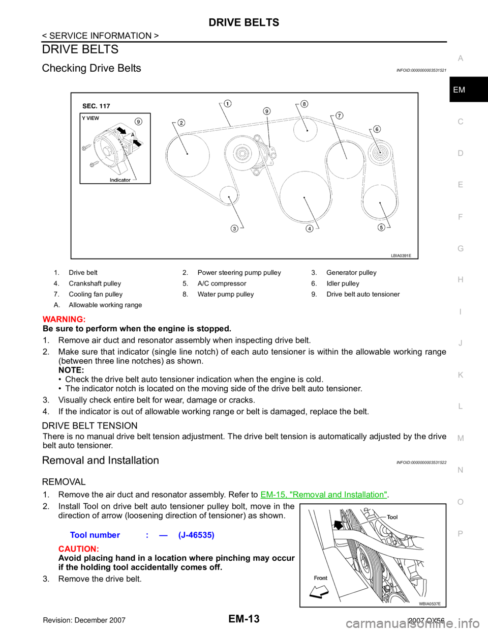
2. Make sure that indicator (single line notch) of eac
h auto tensioner is within the allowable working range
(between three line notches) as shown.
NOTE:
• Check the drive belt auto tensioner indication when the engine is cold.
• The indicator notch is located on the moving side of the drive belt auto tensioner.
3. Visually check entire belt for wear, damage or cracks.
4. If the indicator is out of allowable work ing range or belt is damaged, replace the belt.
DRIVE BELT TENSION
There is no manual drive belt tension adjustment. The driv e belt tension is automatically adjusted by the drive
belt auto tensioner.
Removal and InstallationINFOID:0000000003531522
REMOVAL
1. Remove the air duct and resonator assembly. Refer to EM-15, "Removal and Installation".
2. Install Tool on drive belt auto tensioner pulley bolt, move in the direction of arrow (loosening direction of tensioner) as shown.
CAUTION:
Avoid placing hand in a locat ion where pinching may occur
if the holding tool accidentally comes off.
3. Remove the drive belt.
1. Drive belt 2. Power steering pump pulley 3. Generator pulley
4. Crankshaft pulley 5. A/C compressor 6. Idler pulley
7. Cooling fan pulley 8. Water pump pulley 9. Drive belt auto tensioner
A. Allowable working range
LBIA0391E
Tool number : — (J-46535)
WBIA0537E
Page 1784 of 3061

EM-14
< SERVICE INFORMATION >
DRIVE BELTS
INSTALLATION
Installation is in the reverse order of removal.
CAUTION:
Make sure belt is securely installed around all pulleys.
• Rotate the crankshaft pulley several turns clockwise to equalize belt tension between pulleys.
• Make sure belt tension is within the allowable working range, using the indicator notch on the drive belt auto
tensioner. Refer to EM-13, "
Checking Drive Belts".
Drive Belt Auto Tensioner and Idler PulleyINFOID:0000000003531523
REMOVAL
1. Remove the air duct and resonator assembly. Refer to EM-15, "Removal and Installation".
2. Remove the drive belt. Refer to EM-13, "
Removal and Installation".
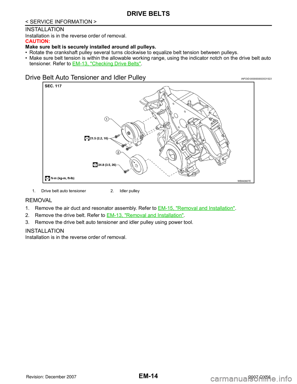
3. Remove the drive belt auto tensioner and idler pulley using power tool.
INSTALLATION
Installation is in the reverse order of removal.
WBIA0607E
1. Drive belt auto tensioner 2. Idler pulley
Page 1809 of 3061

TIMING CHAINEM-39
< SERVICE INFORMATION >
C
DE
F
G H
I
J
K L
M A
EM
NP
O
4. Obtain compression TDC of No. 1 cylinder as follows:
a. Turn the crankshaft pulley clockwise to align the TDC identifica-
tion notch (without paint mark) with the timing indicator on the
front cover.
b. At this time, make sure both intake and exhaust cam lobes of No. 1 cylinder (top front on LH bank) point outside.
• If they do not point outside, turn crankshaft pulley once more.
5. Remove the crankshaft pulley.
a. Loosen the crankshaft pulley bolts using a hammer handle to secure the crankshaft.
b. Remove the crankshaft pulley from the crankshaft using tool. • Remove the crankshaft pulley using suitable tool. Set the boltsin the two bolt holes [M6 x 1.0 mm (0.04 in)] on the front sur-
face.
NOTE:
The dimension between the centers of the two bolt holes is 61
mm (2.40 in).
6. Remove the front cover.
a. Loosen and remove the bolts in the reverse of order shown.
b. Cut the liquid gasket and remove the covers using Tool. CAUTION:
Do not damage mating surfaces.
7. Remove the front oil seal using suitable tool. CAUTION:
Do not damage front cover.
KBIA2476E
KBIA0400J
PBIC0053E
KBIA2477E
Tool number : KV10111100 (J-37228)
KBIA2478E
Page 1816 of 3061

EM-46
< SERVICE INFORMATION >
CAMSHAFT
CAMSHAFT
Removal and InstallationINFOID:0000000003531534
NOTE:
Do not remove the engine assembly to perform this procedure.
REMOVAL
1. Remove the RH bank and LH bank rocker covers. Refer to EM-35, "Removal and Installation".
2. Obtain compression TDC of No. 1 cylinder as follows:
a. Turn the crankshaft pulley clockwise to align the TDC identifica- tion notch (without paint mark) with the timing indicator on the
front cover.
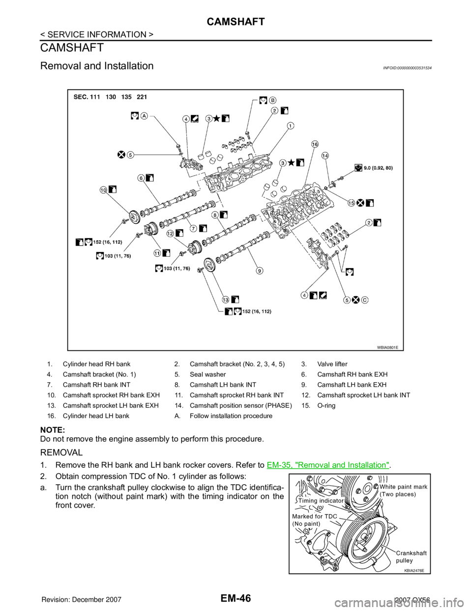
1. Cylinder head RH bank 2. Camshaft bracket (No. 2, 3, 4, 5) 3. Valve lifter
4. Camshaft bracket (No. 1) 5. Seal washer 6. Camshaft RH bank EXH
7. Camshaft RH bank INT 8. Camshaft LH bank INT 9. Camshaft LH bank EXH
10. Camshaft sprocket RH bank EXH 11. Camshaft sprocket RH bank INT 12. Camshaft sprocket LH bank INT
13. Camshaft sprocket LH bank EXH 14. Camshaft position sensor (PHASE) 15. O-ring
16. Cylinder head LH bank A. Follow installation procedure
WBIA0801E
KBIA2476E