4WD INFINITI QX56 2007 Factory Owner's Guide
[x] Cancel search | Manufacturer: INFINITI, Model Year: 2007, Model line: QX56, Model: INFINITI QX56 2007Pages: 3061, PDF Size: 64.56 MB
Page 1892 of 3061
FAX-6
< SERVICE INFORMATION >
WHEEL HUB
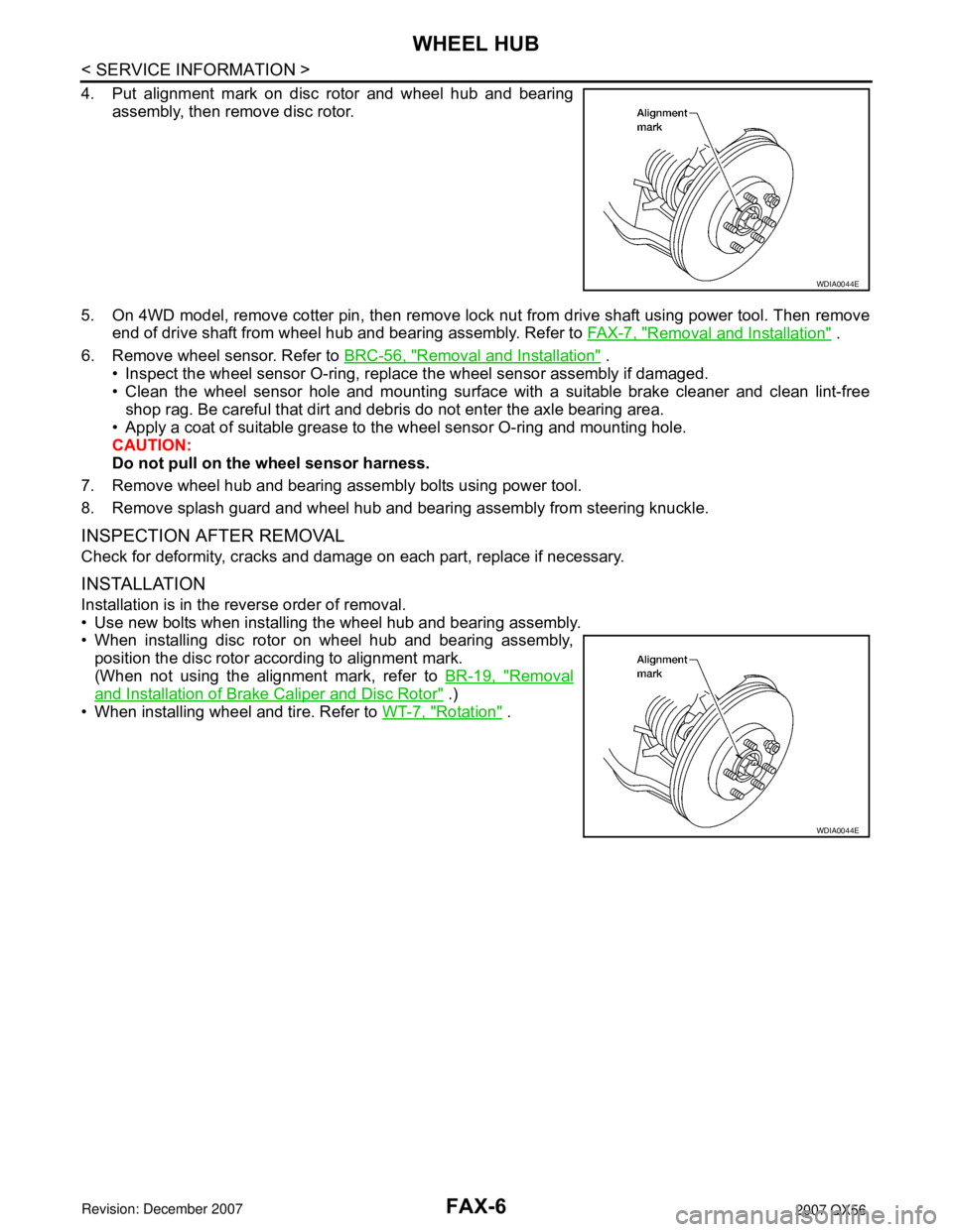
4. Put alignment mark on disc rotor and wheel hub and bearing
assembly, then remove disc rotor.
5. On 4WD model, remove cotter pin, then remove lock nut from drive shaft using power tool. Then remove
end of drive shaft from wheel hub and bearing assembly. Refer to FA X - 7 , "
Removal and Installation" .
6. Remove wheel sensor. Refer to BRC-56, "
Removal and Installation" .
• Inspect the wheel sensor O-ring, replace the wheel sensor assembly if damaged.
• Clean the wheel sensor hole and mounting surface with a suitable brake cleaner and clean lint-free
shop rag. Be careful that dirt and debris do not enter the axle bearing area.
• Apply a coat of suitable grease to the wheel sensor O-ring and mounting hole.
CAUTION:
Do not pull on the wheel sensor harness.
7. Remove wheel hub and bearing assembly bolts using power tool.
8. Remove splash guard and wheel hub and bearing assembly from steering knuckle.
INSPECTION AFTER REMOVAL
Check for deformity, cracks and damage on each part, replace if necessary.
INSTALLATION
Installation is in the reverse order of removal.
• Use new bolts when installing the wheel hub and bearing assembly.
• When installing disc rotor on wheel hub and bearing assembly,
position the disc rotor according to alignment mark.
(When not using the alignment mark, refer to BR-19, "
Removal
and Installation of Brake Caliper and Disc Rotor" .)
• When installing wheel and tire. Refer to WT-7, "
Rotation" .
WDIA0044E
WDIA0044E
Page 1952 of 3061
FSU-6
< SERVICE INFORMATION >
ON-VEHICLE SERVICE
ON-VEHICLE SERVICE
Front Suspension PartsINFOID:0000000003532636
Check front suspension parts for excessive play, cracks, wear and
other damage.
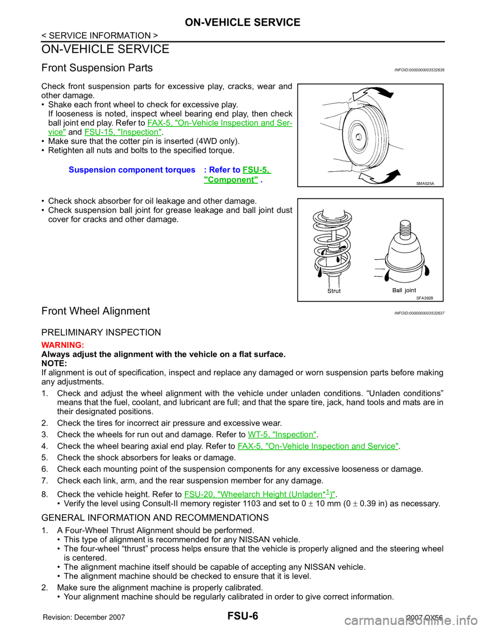
• Shake each front wheel to check for excessive play.
If looseness is noted, inspect wheel bearing end play, then check
ball joint end play. Refer to FA X - 5 , "
On-Vehicle Inspection and Ser-
vice" and FSU-15, "Inspection".
• Make sure that the cotter pin is inserted (4WD only).
• Retighten all nuts and bolts to the specified torque.
• Check shock absorber for oil leakage and other damage.
• Check suspension ball joint for grease leakage and ball joint dust
cover for cracks and other damage.
Front Wheel AlignmentINFOID:0000000003532637
PRELIMINARY INSPECTION
WARNING:
Always adjust the alignment with the vehicle on a flat surface.
NOTE:
If alignment is out of specification, inspect and replace any damaged or worn suspension parts before making
any adjustments.
1. Check and adjust the wheel alignment with the vehicle under unladen conditions. “Unladen conditions”
means that the fuel, coolant, and lubricant are full; and that the spare tire, jack, hand tools and mats are in
their designated positions.
2. Check the tires for incorrect air pressure and excessive wear.
3. Check the wheels for run out and damage. Refer to WT-5, "
Inspection".
4. Check the wheel bearing axial end play. Refer to FA X - 5 , "
On-Vehicle Inspection and Service".
5. Check the shock absorbers for leaks or damage.
6. Check each mounting point of the suspension components for any excessive looseness or damage.
7. Check each link, arm, and the rear suspension member for any damage.
8. Check the vehicle height. Refer to FSU-20, "
Wheelarch Height (Unladen*1)".
• Verify the level using Consult-II memory register 1103 and set to 0 ± 10 mm (0 ± 0.39 in) as necessary.
GENERAL INFORMATION AND RECOMMENDATIONS
1. A Four-Wheel Thrust Alignment should be performed.
• This type of alignment is recommended for any NISSAN vehicle.
• The four-wheel “thrust” process helps ensure that the vehicle is properly aligned and the steering wheel
is centered.
• The alignment machine itself should be capable of accepting any NISSAN vehicle.
• The alignment machine should be checked to ensure that it is level.
2. Make sure the alignment machine is properly calibrated.
• Your alignment machine should be regularly calibrated in order to give correct information.Suspension component torques : Refer to FSU-5,
"Component" . SMA525A
SFA392B
Page 1957 of 3061
COIL SPRING AND SHOCK ABSORBER
FSU-11
< SERVICE INFORMATION >
C
D
F
G
H
I
J
K
L
MA
B
FSU
N
O
P
INSPECTION AFTER DISASSEMBLY
Shock Absorber Assembly
• Check for smooth operation through a full stroke, both compression and extension.
• Check for oil leakage on welded or gland packing portions.
• Check piston rod for cracks, deformation or other damage and replace if necessary.
Mounting Insulator and Rubber Parts
Check cemented rubber-to-metal portion for separation or cracks. Check rubber parts for deterioration and
replace if necessary.
Coil Spring
• Check for cracks, deformation or other damage and replace if necessary.
• Check the free spring height.
ASSEMBLY
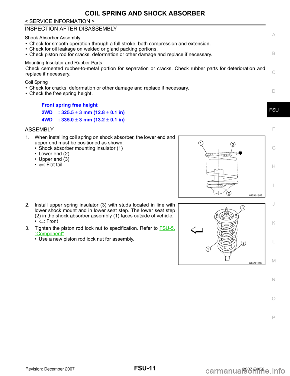
1. When installing coil spring on shock absorber, the lower end and
upper end must be positioned as shown.
• Shock absorber mounting insulator (1)
• Lower end (2)
• Upper end (3)
•⇐: Flat tail
2. Install upper spring insulator (3) with studs located in line with
lower shock mount and in lower seat step. The lower seat step
(2) in the shock absorber assembly (1) faces outside of vehicle.
•⇐: Front
3. Tighten the piston rod lock nut to specification. Refer to FSU-5,
"Component" .
• Use a new piston rod lock nut for assembly.Front spring free height
2WD : 325.5 ± 3 mm (12.8 ± 0.1 in)
4WD : 335.0 ± 3 mm (13.2 ± 0.1 in)
WEIA0154E
WEIA0155E
Page 1965 of 3061
SERVICE DATA AND SPECIFICATIONS (SDS)
FSU-19
< SERVICE INFORMATION >
C
D
F
G
H
I
J
K
L
MA
B
FSU
N
O
P
SERVICE DATA AND SPECIFICATIONS (SDS)
General SpecificationINFOID:0000000003532647
Spring Free HeightINFOID:0000000003532648
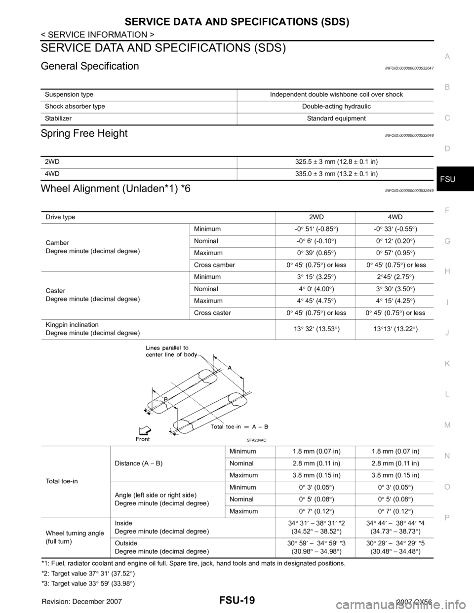
Wheel Alignment (Unladen*1) *6INFOID:0000000003532649
*1: Fuel, radiator coolant and engine oil full. Spare tire, jack, hand tools and mats in designated positions.
*2: Target value 37° 31′ (37.52°)
*3: Target value 33° 59′ (33.98°) Suspension type Independent double wishbone coil over shock
Shock absorber type Double-acting hydraulic
StabilizerStandard equipment
2WD325.5 ± 3 mm (12.8 ± 0.1 in)
4WD335.0 ± 3 mm (13.2 ± 0.1 in)
Drive type2WD 4WD
Camber
Degree minute (decimal degree)Minimum -0° 51′ (-0.85°)-0° 33′ (-0.55°)
Nominal -0° 6′ (-0.10°)0° 12′ (0.20°)
Maximum 0° 39′ (0.65°)0° 57′ (0.95°)
Cross camber 0° 45′ (0.75°) or less 0° 45′ (0.75°) or less
Caster
Degree minute (decimal degree)Minimum 3° 15′ (3.25°)2°45′ (2.75°)
Nominal 4° 0′ (4.00°)3° 30′ (3.50°)
Maximum 4° 45′ (4.75°)4° 15′ (4.25°)
Cross caster 0° 45′
(0.75°) or less 0° 45′ (0.75°) or less
Kingpin inclination
Degree minute (decimal degree)13° 32′ (13.53°)13°13′ (13.22°)
Total toe-inDistance (A − B)Minimum 1.8 mm (0.07 in) 1.8 mm (0.07 in)
Nominal 2.8 mm (0.11 in) 2.8 mm (0.11 in)
Maximum 3.8 mm (0.15 in) 3.8 mm (0.15 in)
Angle (left side or right side)
Degree minute (decimal degree)Minimum 0° 3′ (0.05°)0° 3′ (0.05°)
Nominal 0° 5′ (0.08°)0° 5′ (0.08°)
Maximum 0° 7′ (0.12°)0° 7′ (0.12°)
Wheel turning angle
(full turn)Inside
Degree minute (decimal degree)34° 31′ – 38° 31′ *2
(34.52° – 38.52°)34° 44′ – 38° 44′ *4
(34.73° – 38.73
°)
Outside
Degree minute (decimal degree)30° 59′ – 34° 59′ *3
(30.98° – 34.98°)30° 29′ – 34° 29′ *5
(30.48° – 34.48°)
SFA234AC
Page 1966 of 3061
FSU-20
< SERVICE INFORMATION >
SERVICE DATA AND SPECIFICATIONS (SDS)
*4: Target value 37° 44′ (37.73°)
*5: Target value 33° 29′ (33.48°)
*6: Some vehicles may be equipped with straight (non-adjustable) lower link bolts and washers. in order to adjust camber and caster on
these vehicles, first replace the lower link bolts and washers with adjustable (cam) bolts and washers.
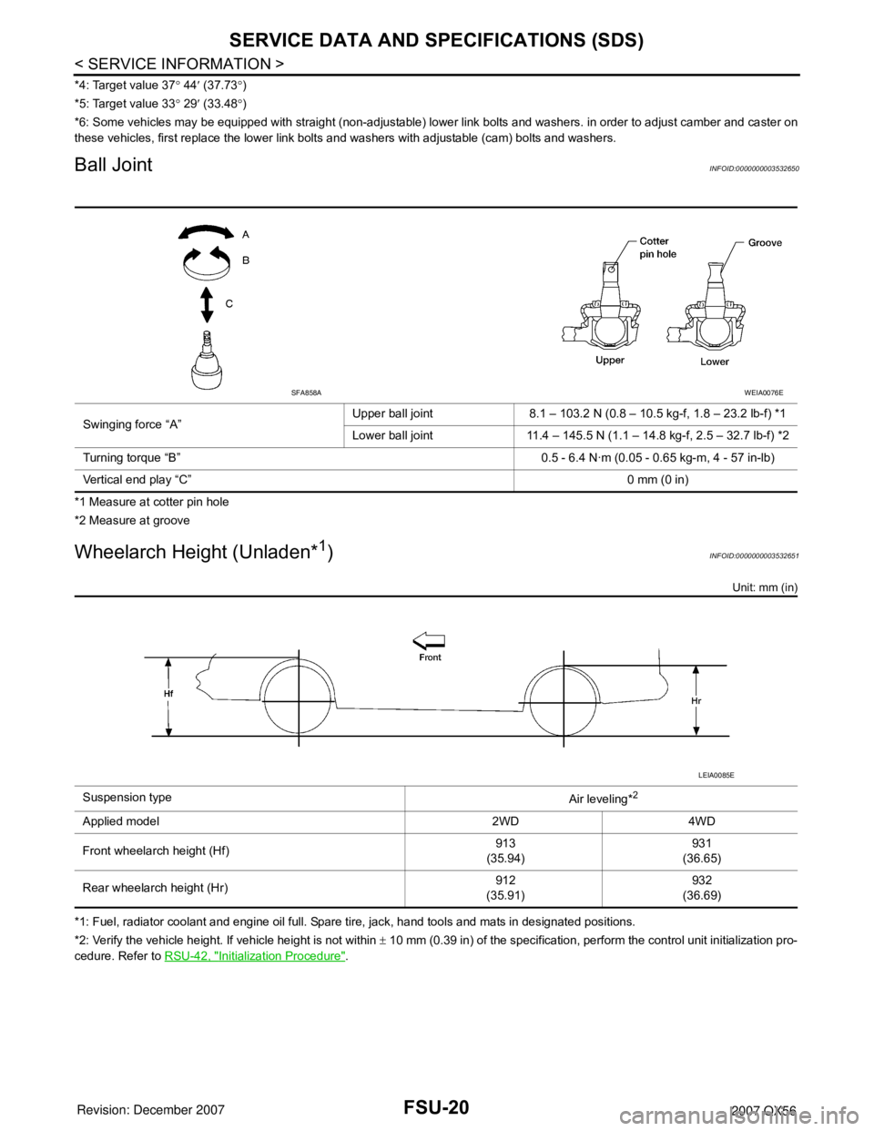
Ball JointINFOID:0000000003532650
*1 Measure at cotter pin hole
*2 Measure at groove
Wheelarch Height (Unladen*1)INFOID:0000000003532651
Unit: mm (in)
*1: Fuel, radiator coolant and engine oil full. Spare tire, jack, hand tools and mats in designated positions.
*2: Verify the vehicle height. If vehicle height is not within ± 10 mm (0.39 in) of the specification, perform the control unit initialization pro-
cedure. Refer to RSU-42, "
Initialization Procedure". Swinging force “A”Upper ball joint 8.1 – 103.2 N (0.8 – 10.5 kg-f, 1.8 – 23.2 lb-f) *1
Lower ball joint 11.4 – 145.5 N (1.1 – 14.8 kg-f, 2.5 – 32.7 lb-f) *2
Turning torque “B” 0.5 - 6.4 N·m (0.05 - 0.65 kg-m, 4 - 57 in-lb)
Vertical end play “C”0 mm (0 in)
SFA858AWEIA0076E
Suspension type
Air leveling*2
Applied model 2WD 4WD
Front wheelarch height (Hf)913
(35.94)931
(36.65)
Rear wheelarch height (Hr)912
(35.91)932
(36.69)
LEIA0085E
Page 2001 of 3061

CONSULT-II CHECKING SYSTEM
GI-35
< SERVICE INFORMATION >
C
D
E
F
G
H
I
J
K
L
MB
GI
N
O
PCONSULT-II CHECKING SYSTEM
DescriptionINFOID:0000000003531490
• CONSULT-II is a hand-held type tester. When it is connected with a diagnostic connector equipped on the
vehicle side, it will communicate with the control unit equipped in the vehicle and then enable various kinds
of diagnostic tests.
• Refer to “CONSULT-II Software Operation Manual” for more information.
Function and System ApplicationINFOID:0000000003531491
x: Applicable.
*1: If equipped.Diagnostic test mode Function
ENGINE
A/T
ICC
*1
ABS
AIR BAG
IPDM E/R
BCM
AUTO DRIVE POS.
REARVIEW CAMERA
AIR LEVELIZER
ALL MODE AWD/4WD
HVAC
NVIS (NATS)
*2
NVIS (NATS BCM OR S/ENT)
*2
Work supportThis mode enables a technician to adjust some devices
faster and more accurately by following the indications on
CONSULT-II.xxxx - - xxxxx - - -
Self-diagnostic Self-diagnostic can be performed quickly. ----x---------
Self-diagnostic results Self-diagnostic results can be read and erased quickly. xxxx - xxx - xxxxx
Trouble diagnostic
recordCurrent self-diagnostic results and all trouble diagnostic
records previously stored can be read.--- - x---------
Data monitor Input/Output data in the ECM can be read. xxxx - x - xxxxx - -
Data monitor (spec) Data monitor specification can be read. x-------------
CAN diagnosis support
monitorThe communication condition of CAN communication line
can be read.xxxx - xxx - - xx - -
Active testDiagnostic Test Mode in which CONSULT-II drives some
actuators apart from the ECMs and also shifts some param-
eters in a specified range.x-xx-x-x-x----
Function testThis mode can show results of self-diagnosis of ECU with
either “OK” or “NG”. For engines, more practical tests re-
garding sensors/switches and/or actuators are available.xx-xx- --- -----
DTC & SRT confirma-
tionThe results of SRT (System Readiness Test) and the self-
diagnosis status/result can be confirmed.x-------------
DTC work supportThe operating condition to confirm Diagnosis Trouble
Codes can be selected.xx------------
ECM/ECU part number ECM/ECU part number can be read.
xxxx - -xx
xxxx - -
ECU discriminated No.Classification number of a replacement ECU can be read to
prevent an incorrect ECU from being installed.----x---------
Passenger Airbag Displays the STATUS (readiness) of the front passenger air
bag.----x---------
Configuration Sets control module parameters to match vehicle options. ------x-------
PIN read
*3This mode shows the BCM-specific 5-digit code. -------------x
Control unit
initialization
*3All registered ignition key IDs in NATS components can be
initialized and new IDs can be registered.------------x-
Page 2008 of 3061
GI-42
< SERVICE INFORMATION >
TOW TRUCK TOWING
TOW TRUCK TOWING
Tow Truck TowingINFOID:0000000003531499
WARNING:
• Never get under the vehicle while it is supported only by the jack. Always use safety stands to sup-
port the frame when you have to get under the vehicle.
• Place wheel chocks at both front and back of the wheels on the ground.
CAUTION:
• All applicable State or Provincial (in Canada) laws and local laws regarding the towing operation
must be obeyed.
• It is necessary to use proper towing equipment to avoid possible damage during towing operation.
Towing is in accordance with Towing Procedure Manual at dealer.
• Always attach safety chains before towing.
• When towing, make sure that the transmission, steering system and powertrain are in good order. If
any unit is damaged, dollies must be used.
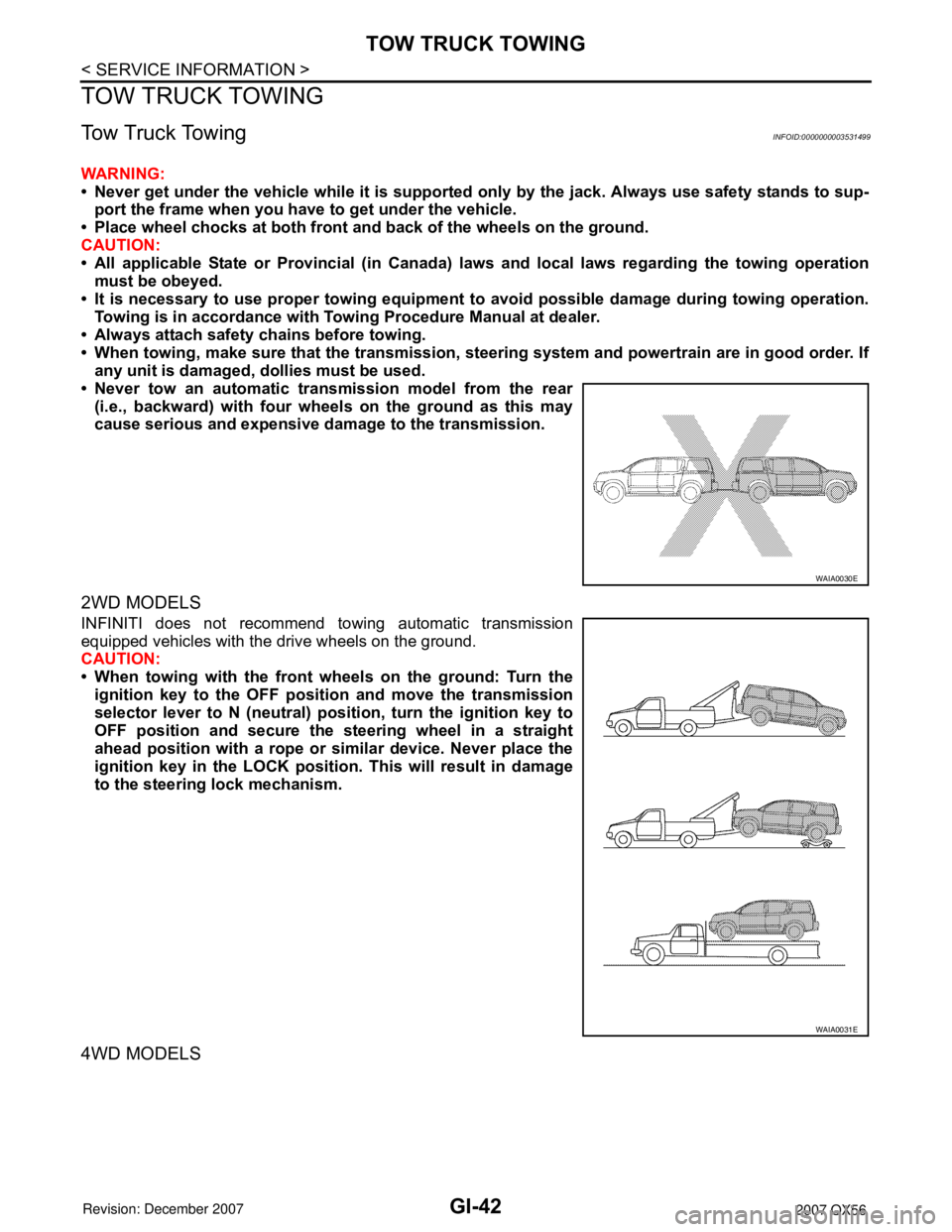
• Never tow an automatic transmission model from the rear
(i.e., backward) with four wheels on the ground as this may
cause serious and expensive damage to the transmission.
2WD MODELS
INFINITI does not recommend towing automatic transmission
equipped vehicles with the drive wheels on the ground.
CAUTION:
• When towing with the front wheels on the ground: Turn the
ignition key to the OFF position and move the transmission
selector lever to N (neutral) position, turn the ignition key to
OFF position and secure the steering wheel in a straight
ahead position with a rope or similar device. Never place the
ignition key in the LOCK position. This will result in damage
to the steering lock mechanism.
4WD MODELS
WAIA0030E
WAIA0031E
Page 2009 of 3061

TOW TRUCK TOWING
GI-43
< SERVICE INFORMATION >
C
D
E
F
G
H
I
J
K
L
MB
GI
N
O
P
INFINITI does not recommend towing automatic transmission
equipped vehicles with the drive wheels on the ground.
CAUTION:
• Never tow 4WD models with any of the wheels on the ground
as this may cause serious and expensive damage to the
transfer case and transmission.
Towing Point
CAUTION:
Never tow the vehicle using only the towing points. To avoid
damaging the vehicle body, use proper towing equipment when
towing.
Vehicle Recovery (Freeing a stuck vehicle)INFOID:0000000003531500
•Tow chains or cables must be attached only to the main structural members of the vehicle or the
towing hooks (if so equipped). Otherwise, the vehicle body will be damaged.
•Use the towing hook (if so equipped) only to free a vehicle stuck in sand, snow, mud, etc. Never tow
the vehicle for a long distance using only the towing hook.
•The towing hook is under tremendous force when used to free a stuck vehicle. Never pull the hook at
an angle.
•Always pull the cable straight out from the front or rear of the vehicle.
•Pulling devices should be routed so they do not touch any part of the suspension, steering, brake, or
cooling systems.
•Pulling devices such as ropes or canvas straps are not recommended for use in vehicle towing or
recovery.
WARNING:
• Stand clear of a stuck vehicle.
• Do not spin your tires at high speed. This could cause them to explode and result in serious injury.
Parts of your vehicle could also overheat and be damaged.
WAIA0032E
WAIA0055E
Page 2012 of 3061

GI-46
< SERVICE INFORMATION >
IDENTIFICATION INFORMATION
IDENTIFICATION INFORMATION
Model VariationINFOID:0000000003531503
Prefix and suffix designations:
Drive Type Body Engine Transmission Destination Grade Model
2WD Wagon VK56DE RE5R05A (5A/T) U.S.A. LE JPKALVK-EUA
4WD Wagon VK56DE RE5R05A (5A/T)U.S.A.
LEJPKWLVK-EUA
Canada JPKWLVK-ENA
Position Character Qualifier Definition
1 J Body type J: Wagon
2
PK Engine PK: VK56DE
3
4AAxleA: 2WD
W: 4WD
5LDrive L: LH
6 V Grade V: LE
7 K Transmission K: RE5R05A (5A/T)
8
I46 Model I46: 2007 QX56 9
10
11 E I n t a k e E : E G I
12 U ZoneN: Canada
U: Federal
13 A Equipment A: Standard
14
XXXXX Option Codes Option Codes 15
16
17
18
Page 2013 of 3061

IDENTIFICATION INFORMATION
GI-47
< SERVICE INFORMATION >
C
D
E
F
G
H
I
J
K
L
MB
GI
N
O
P
Identification NumberINFOID:0000000003531504
VEHICLE IDENTIFICATION NUMBER ARRANGEMENT
1. Emission control information label 2. Tire placard 3. F.M.V.S.S. certification label
4. Vehicle identification number plate 5. Vacuum hose diagram
WAIA0053E
Position Character Qualifier Definition
1
5N3 Manufacturer 5N3: USA produced multi-purpose vehicle 2
3
4 A Engine type A: VK56DE
5 A Vehicle line A: Infiniti QX56
6 0 Model change (0-9)
7 8 Body type 8: 4 door wagon
8AGross vehicle
weight ratingA: 2WD, 4-wheel ABS, Class E
B: 4WD, 4-wheel ABS, Class E
9 * Check digit(0 to 9 or X) The code for the check digit is determined by a mathematical com-
putation.
10 7 Model year 2007
11 NManufacturing
plantN: Canton Mississippi
12
XXXXXVehicle serial num-
berChassis number 13
14
15
16
17