4WD INFINITI QX56 2007 Factory Owner's Manual
[x] Cancel search | Manufacturer: INFINITI, Model Year: 2007, Model line: QX56, Model: INFINITI QX56 2007Pages: 3061, PDF Size: 64.56 MB
Page 353 of 3061
ASSEMBLY
AT-283
< SERVICE INFORMATION >
D
E
F
G
H
I
J
K
L
MA
B
AT
N
O
P
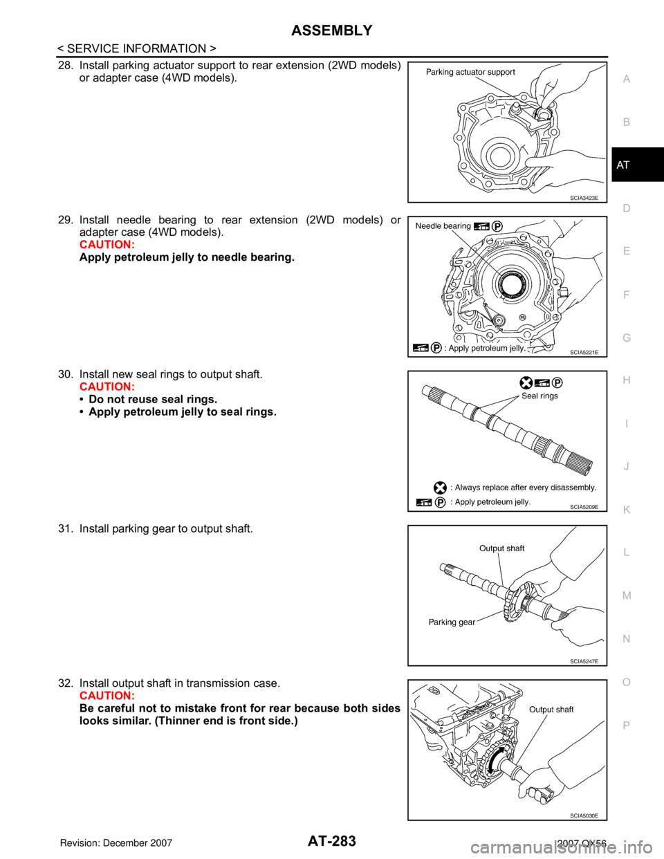
28. Install parking actuator support to rear extension (2WD models)
or adapter case (4WD models).
29. Install needle bearing to rear extension (2WD models) or
adapter case (4WD models).
CAUTION:
Apply petroleum jelly to needle bearing.
30. Install new seal rings to output shaft.
CAUTION:
• Do not reuse seal rings.
• Apply petroleum jelly to seal rings.
31. Install parking gear to output shaft.
32. Install output shaft in transmission case.
CAUTION:
Be careful not to mistake front for rear because both sides
looks similar. (Thinner end is front side.)
SCIA3423E
SCIA5221E
SCIA5209E
SCIA5247E
SCIA5030E
Page 354 of 3061
AT-284
< SERVICE INFORMATION >
ASSEMBLY
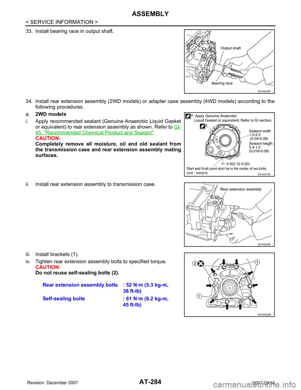
33. Install bearing race in output shaft.
34. Install rear extension assembly (2WD models) or adapter case assembly (4WD models) according to the
following procedures.
a.2WD models
i. Apply recommended sealant (Genuine Anaerobic Liquid Gasket
or equivalent) to rear extension assembly as shown. Refer to GI-
45, "Recommended Chemical Product and Sealant".
CAUTION:
Completely remove all moisture, oil and old sealant from
the transmission case and rear extension assembly mating
surfaces.
ii. Install rear extension assembly to transmission case.
iii. Install brackets (1).
iv. Tighten rear extension assembly bolts to specified torque.
CAUTION:
Do not reuse self-sealing bolts (2).
SCIA5245E
SCIA5212E
SCIA5029E
Rear extension assembly bolts : 52 N·m (5.3 kg-m,
38 ft-lb)
Self-sealing bolts : 61 N·m (6.2 kg-m,
45 ft-lb)
WCIA0562E
Page 355 of 3061
ASSEMBLY
AT-285
< SERVICE INFORMATION >
D
E
F
G
H
I
J
K
L
MA
B
AT
N
O
P
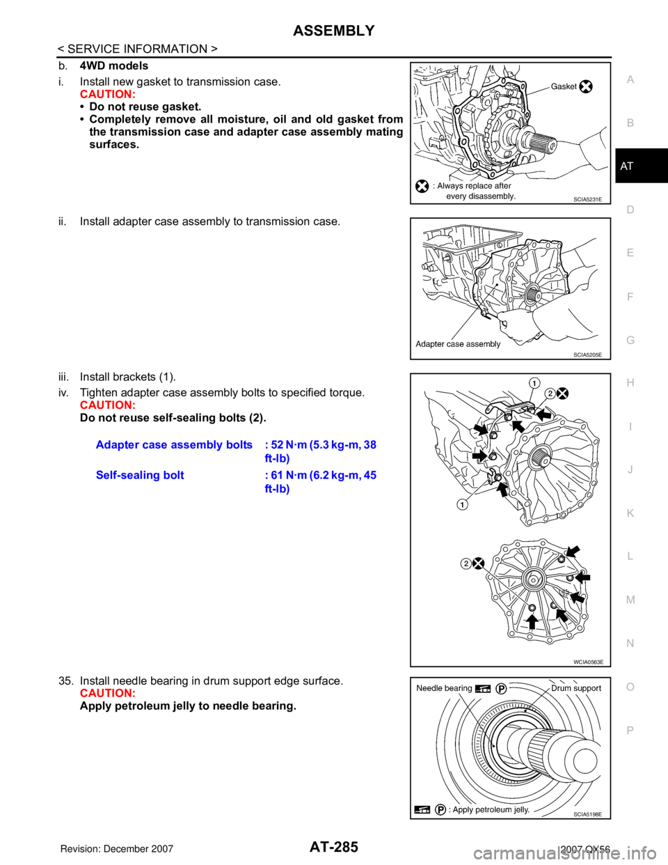
b.4WD models
i. Install new gasket to transmission case.
CAUTION:
• Do not reuse gasket.
• Completely remove all moisture, oil and old gasket from
the transmission case and adapter case assembly mating
surfaces.
ii. Install adapter case assembly to transmission case.
iii. Install brackets (1).
iv. Tighten adapter case assembly bolts to specified torque.
CAUTION:
Do not reuse self-sealing bolts (2).
35. Install needle bearing in drum support edge surface.
CAUTION:
Apply petroleum jelly to needle bearing.
SCIA5231E
SCIA5205E
Adapter case assembly bolts : 52 N·m (5.3 kg-m, 38
ft-lb)
Self-sealing bolt : 61 N·m (6.2 kg-m, 45
ft-lb)
WCIA0563E
SCIA5198E
Page 368 of 3061
AT-298
< SERVICE INFORMATION >
SERVICE DATA AND SPECIFICATIONS (SDS)
SERVICE DATA AND SPECIFICATIONS (SDS)
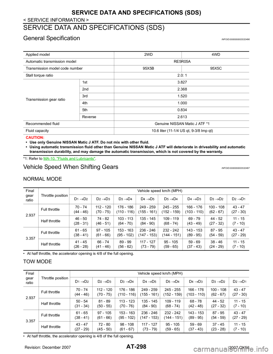
General SpecificationINFOID:0000000003532496
*1: Refer to MA-10, "Fluids and Lubricants".
Vehicle Speed When Shifting GearsINFOID:0000000003532497
NORMAL MODE
• At half throttle, the accelerator opening is 4/8 of the full opening.
TOW MODE
• At half throttle, the accelerator opening is 4/8 of the full opening.Applied model 2WD 4WD
Automatic transmission model RE5R05A
Transmission model code number 95X5B 95X5C
Stall torque ratio2.0: 1
Transmission gear ratio1st 3.827
2nd 2.368
3rd 1.520
4th 1.000
5th 0.834
Reverse 2.613
Recommended fluid Genuine NISSAN Matic J ATF *1
Fluid capacity 10.6 liter (11-1/4 US qt, 9-3/8 Imp qt)
CAUTION:
• Use only Genuine NISSAN Matic J ATF. Do not mix with other fluid.
• Using automatic transmission fluid other than Genuine NISSAN Matic J ATF will deteriorate in driveability and automatic
transmission durability, and may damage the automatic transmission, which is not covered by the warranty.
Final
gear
ratioThrottle positionVehicle speed km/h (MPH)
D
1 →D2D2 →D3D3 →D4D4 →D5D5 →D4D4 →D3D3 →D2D2 →D1
2.937Full throttle 70 - 74
(44 - 46)112 - 120
(70 - 75)176 - 186
(110 - 116)249 - 259
(155 - 161)245 - 255
(152 - 159)166 - 176
(103 - 110)100 - 108
(62 - 67)43 - 47
(27 - 30)
Half throttle 46 - 50
(28 - 31)74 - 82
(46 - 51)103 - 113
(64 - 70)135 - 145
(84 - 90)109 - 119
(68 - 74)69 - 79
(43 - 49)44 - 52
(27 - 32)11 - 1 5
(7 - 10)
3.357Full throttle 61 - 65
(38 - 41)97 - 105
(61 - 66)153 - 163
(95 - 102)236 - 246
(147 - 153)232 - 242
(144 - 151)143 - 153
(89 - 95)87 - 95
(54 - 59)43 - 47
(27 - 29)
Half throttle 41 - 45
(26 - 28)66 - 74
(41 - 46)89 - 99
(56 - 62)117 - 127
(73 - 79)95 - 105
(59 - 65)59 - 69
(37 - 43)38 - 46
(24 - 29)11 - 1 5
(7 - 10)
Final
gear
ratioThrottle positionVehicle speed km/h (MPH)
D
1 →D2D2 →D3D3 →D4D4 →D5D5 →D4D4 →D3D3 →D2D2 →D1
2.937Full throttle 70 - 74
(44 - 46)112 - 120
(70 - 75)176 - 186
(110 - 116)249 - 259
(155 - 161)245 - 255
(152 - 159)166 - 176
(103 - 110)100 - 108
(62 - 67)43 - 47
(27 - 30)
Half throttle 50 - 54
(31 - 34)81 - 89
(50 - 55)113 - 123
(70 - 76)135 - 145
(84 - 90)109 - 119
(68 - 74)68 - 78
(42 - 48)44 - 52
(27 - 32)11 - 1 5
(7 - 10)
3.357Full throttle 61 - 65
(38 - 41)97 - 105
(61 - 66)153 - 163
(95 - 102)236 - 246
(147 - 153)232 - 242
(144 - 151)143 - 153
(89 - 95)87 - 95
(54 - 59)43 - 47
(27 - 29)
Half throttle 43 - 47
(27 - 29)72 - 80
(45 - 50)98 - 108
(61 - 67)117 - 127
(73 - 79)95 - 105
(59 - 65)59 - 69
(37 - 43)37 - 45
(23 - 28)11 - 1 5
(7 - 10)
Page 959 of 3061
![INFINITI QX56 2007 Factory Owners Manual TROUBLE DIAGNOSIS
BRC-31
< SERVICE INFORMATION >[VDC/TCS/ABS]
C
D
E
G
H
I
J
K
L
MA
B
BRC
N
O
P
RR LH IN SOL
(ON/OFF)–××Rear LH IN ABS solenoid (ON/OFF)
status is displayed.
RR LH OUT SOL
(ON/OFF) INFINITI QX56 2007 Factory Owners Manual TROUBLE DIAGNOSIS
BRC-31
< SERVICE INFORMATION >[VDC/TCS/ABS]
C
D
E
G
H
I
J
K
L
MA
B
BRC
N
O
P
RR LH IN SOL
(ON/OFF)–××Rear LH IN ABS solenoid (ON/OFF)
status is displayed.
RR LH OUT SOL
(ON/OFF)](/img/42/57029/w960_57029-958.png)
TROUBLE DIAGNOSIS
BRC-31
< SERVICE INFORMATION >[VDC/TCS/ABS]
C
D
E
G
H
I
J
K
L
MA
B
BRC
N
O
P
RR LH IN SOL
(ON/OFF)–××Rear LH IN ABS solenoid (ON/OFF)
status is displayed.
RR LH OUT SOL
(ON/OFF)–××Rear LH OUT ABS solenoid (ON/
OFF) status is displayed.
OFF LAMP
(ON/OFF)–××OFF Lamp (ON/OFF) status is dis-
played.
MOTOR RELAY
(ON/OFF)–××ABS motor relay signal (ON/OFF)
status is displayed.
ACTUATOR RLY
(ON/OFF)– ××ABS actuator relay signal (ON/OFF)
status is displayed.
CV1
(ON/OFF)––×Front side switch-over solenoid
valve (cut valve) (ON/OFF) status is
displayed.
CV2
(ON/OFF)––×Rear side switch-over solenoid
valve (cut-valve) (ON/OFF) status is
displayed.
SV1
(ON/OFF)––×Front side switch-over solenoid
valve (suction valve) (ON/OFF) sta-
tus is displayed.
SV2
(ON/OFF)––×Rear side switch-over solenoid
valve (suction valve) (ON/OFF) sta-
tus is displayed.
VDC FAIL SIG
(ON/OFF)––×VDC fail signal (ON/OFF) status is
displayed.
TCS FAIL SIG
(ON/OFF)––×TCS fail signal (ON/OFF) status is
displayed.
ABS FAIL SIG
(ON/OFF)––×ABS fail signal (ON/OFF) status is
displayed.
EBD FAIL SIG
(ON/OFF)––×EBD fail signal (ON/OFF) status is
displayed.
FLUID LEV SW
(ON/OFF)×–×Brake fluid level switch (ON/OFF)
status is displayed.
EBD SIGNAL
(ON/OFF)––×EBD operation (ON/OFF) status is
displayed.
ABS SIGNAL
(ON/OFF)––×ABS operation (ON/OFF) status is
displayed.
TCS SIGNAL
(ON/OFF)––×TCS operation (ON/OFF) status is
displayed.
VDC SIGNAL
(ON/OFF)––×VDC operation (ON/OFF) status is
displayed.
EBD WARN LAMP – –×Brake warning lamp (ON/OFF) sta-
tus is displayed.
SLCT LVR POSI×××Shift position judged by PNP switch
signal.
R POSI SIG – –×Shift position judged by PNP switch
signal.
4WD FAIL REQ – –×The state of 4WD controller is dis-
played by CAN communication sig-
nal.
2WD/4WD – –×It recognizes on software whether it
is 2WD and whether it is in 4WD
state. Item
(Unit)Data monitor item selection
Remarks
ECU INPUT
SIGNALSMAIN
SIGNALSSELECTION
FROM MENU
Page 1043 of 3061

DI-32
< SERVICE INFORMATION >
WARNING LAMPS
4WD Models
Oil Pressure Warning Lamp Stays Off (Ignition Switch ON)INFOID:0000000003533506
1.CHECK SELF-DIAGNOSTIC RESULTS OF IPDM E/R
Select "IPDM E/R" on CONSULT-II, and perform self-diagnosis of IPDM E/R. Refer to PG-18, "
CONSULT-II
Function (IPDM E/R)".
Self-diagnostic results content
WKWA5140E
Page 1791 of 3061

EXHAUST MANIFOLD AND THREE WAY CATALYST
EM
-21
< ON-VE HICLE REPAIR >
C
D
E
F
G
H
I
J
K
L
M
A
EM
N
P
O
EXHAUST MANIFOLD AND THREE WA Y CATALYST
Exploded ViewINFOID:000 0000004918768
Removal and Installa tionINFOID:000 0000005190289
REMOVAL
WARNING:
Perf
o rm the wo rk when the exhau st and cooling system have co oled sufficiently.
1. Remove the engine undercover (rear) using power tool (4WD models).
2. Remove front final drive assembly (4WD models). Refer to
FFD-12, "Removal and Installation".
3. Remove the main muffler assembly and center exhaust tube. Refer to EX-3, "Removal and Installation".
4. Remove the front exhaust tubes. Refer to EX-3, "Removal and Installation".
5. Remove front tires. Refer to WT-7, "Rotation".
6. Remove fender protectors. Refer to EI-22, "Removal and Installation".
7. Remove the LH and RH air fuel ratio A/F sensors.
•Follow steps below to remove each air fuel ratio A/F sensor.
a. Remove the harness connector of each air fuel ratio A/F sensor, and harness from bracket and middle
clamp
.
1.Air fuel ratio A/F sensor 1 (bank 2)2. Exhaust manifold cover (bank 2)3. Exhaust manifold (bank 2)
4. Gaskets5.Exhaust manifold (bank 1)6. Exhaust manifold cover (bank 1)
7. Air fuel ratio A/F sensor 1 (bank 1)A.UpB.Coated face
C. Manifold sideD. Up markFront
AWBIA04 53GB
Page 1832 of 3061

EM-62
< SERVICE INFORMATION >
OIL SEAL
3. Remove the front oil seal using suitable tool.CAUTION:
Do not damage front cover and oil pump drive spacer.
INSTALLATION
1. Apply new engine oil to both the oil seal lip and dust seal lip of the new front oil seal.
2. Install the front oil seal.• Install the front oil seal so that each seal lip is oriented as
shown.
• Press-fit until the height of the front oil seal is level with the mounting surface using suitable tool.
CAUTION:
• Do not damage front timing chain case and crankshaft.
• Press-fit straight and avoid causing burrs or tilting oil
seal.
3. Installation of the remaining components is in the reverse order of removal.
Removal and Installation of Rear Oil SealINFOID:0000000003531539
REMOVAL
1. Remove the transmission assembly. Refer to AT-223, "Removal and Installation (2WD)" or AT-225,
"Removal and Installation (4WD)".
2. Lock the drive plate using Tool A.
CAUTION:
Do not damage the drive plat e. Especially, avoid deforming
and damaging the signal plat e teeth (circumference posi-
tion).
Keep magnetic materials away from signal plate.
NOTE:
Remove the bolts diagonally.
SBIA0359E
SEM715A
PBIC2931E
Tool number : — (J-47245)
LBIA0455E
Page 1844 of 3061
EM-74
< SERVICE INFORMATION >
ENGINE ASSEMBLY
ENGINE ASSEMBLY
Removal and InstallationINFOID:0000000003531544
WARNING:
• Situate vehicle on a flat and solid surface.
• Place chocks at front and back of rear wheels.
• For engines not equipped with engine slingers, attach proper slingers and bolts described in PARTS
CATALOG.
CAUTION:
• Always be careful to work safely, avoid forceful or uninstructed operations.
• Do not start working until exhaust system and engine coolant are cooled sufficiently.
• If items or work required are not covered by the engine section, refer to the applicable sections.
• Always use the support point specified for lifting.
• Use either 2-point lift type or separate type lift. If board-on type is used for unavoidable reasons,
support at the rear axle jacking point with transmission jack or similar tool before starting work, in
preparation for the backward shift of center of gravity.
• For supporting points for lifting and jacking point at rear axle, refer to GI-40, "
Garage Jack and
Safety Stand".
REMOVAL
Preparation
1. Drain the engine coolant. Refer to CO-9, "Changing Engine Coolant".
2. Partially drain the A/T fluid. Refer to AT-13, "
Changing Automatic Transmission Fluid (ATF)".
3. Release the fuel pressure. Refer to EC-80, "
Fuel Pressure Check".
4. Remove the engine hood. Refer to BL-12, "
Removal and Installation of Hood Assembly".
5. Remove the cowl extension. Refer to EI-17, "
Removal and Installation".
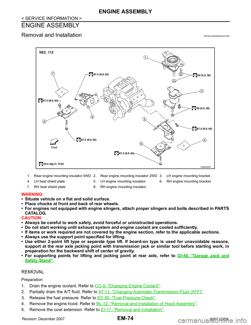
1. Rear engine mounting insulator 4WD 2. Rear engine mounting insulator 2WD 3. LH engine mounting bracket
4. LH heat shield plate 5. LH engine mounting insulator 6. RH engine mounting bracket
7. RH heat shield plate 8. RH engine mounting insulator
LBIA0397E
Page 1845 of 3061
ENGINE ASSEMBLY
EM-75
< SERVICE INFORMATION >
C
D
E
F
G
H
I
J
K
L
MA
EM
N
P O
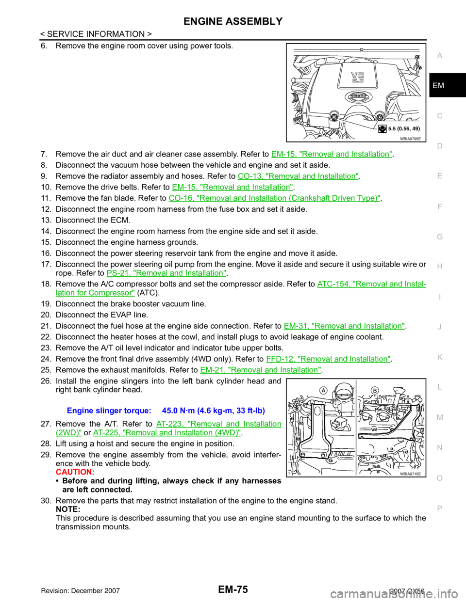
6. Remove the engine room cover using power tools.
7. Remove the air duct and air cleaner case assembly. Refer to EM-15, "
Removal and Installation".
8. Disconnect the vacuum hose between the vehicle and engine and set it aside.
9. Remove the radiator assembly and hoses. Refer to CO-13, "
Removal and Installation".
10. Remove the drive belts. Refer to EM-15, "
Removal and Installation".
11. Remove the fan blade. Refer to CO-16, "
Removal and Installation (Crankshaft Driven Type)".
12. Disconnect the engine room harness from the fuse box and set it aside.
13. Disconnect the ECM.
14. Disconnect the engine room harness from the engine side and set it aside.
15. Disconnect the engine harness grounds.
16. Disconnect the power steering reservoir tank from the engine and move it aside.
17. Disconnect the power steering oil pump from the engine. Move it aside and secure it using suitable wire or
rope. Refer to PS-21, "
Removal and Installation".
18. Remove the A/C compressor bolts and set the compressor aside. Refer to ATC-154, "
Removal and Instal-
lation for Compressor" (ATC).
19. Disconnect the brake booster vacuum line.
20. Disconnect the EVAP line.
21. Disconnect the fuel hose at the engine side connection. Refer to EM-31, "
Removal and Installation".
22. Disconnect the heater hoses at the cowl, and install plugs to avoid leakage of engine coolant.
23. Remove the A/T oil level indicator and indicator tube upper bolts.
24. Remove the front final drive assembly (4WD only). Refer to FFD-12, "
Removal and Installation".
25. Remove the exhaust manifolds. Refer to EM-21, "
Removal and Installation".
26. Install the engine slingers into the left bank cylinder head and
right bank cylinder head.
27. Remove the A/T. Refer to AT-223, "
Removal and Installation
(2WD)" or AT-225, "Removal and Installation (4WD)".
28. Lift using a hoist and secure the engine in position.
29. Remove the engine assembly from the vehicle, avoid interfer-
ence with the vehicle body.
CAUTION:
• Before and during lifting, always check if any harnesses
are left connected.
30. Remove the parts that may restrict installation of the engine to the engine stand.
NOTE:
This procedure is described assuming that you use an engine stand mounting to the surface to which the
transmission mounts.
WBIA0795E
Engine slinger torque: 45.0 N·m (4.6 kg-m, 33 ft-lb)
WBIA0715E