4WD INFINITI QX56 2007 Factory Workshop Manual
[x] Cancel search | Manufacturer: INFINITI, Model Year: 2007, Model line: QX56, Model: INFINITI QX56 2007Pages: 3061, PDF Size: 64.56 MB
Page 2368 of 3061

MA-6
< SERVICE INFORMATION >
PERIODIC MAINTENANCE
PERIODIC MAINTENANCE
Introduction of Periodic MaintenanceINFOID:0000000003533860
Two different maintenance schedules are provided, and should be used, depending upon the conditions in
which the vehicle is mainly operated. After 60,000 miles (96,000 km) or 48 months, continue the periodic
maintenance at the same mileage or time intervals, whichever comes first.
Maintenance for Off-road Driving (4WD only)INFOID:0000000003533861
After driving the vehicle off-road through sand, mud, or water; more frequent maintenance may be required for
the following items:
Brake pads and rotors
Brake lines and hoses
Rear final drive oil, transmission fluid, and transfer fluid
Steering linkage
Drive shafts
Engine air cleaner filter
In-cabin microfilters
Schedule 1INFOID:0000000003533862
EMISSION CONTROL SYSTEM MAINTENANCE
Abbreviations: R = Replace. I = Inspect. Correct or replace if necessary. [ ]: At the mileage intervals only
Schedule 1Follow Periodic Maintenance Schedule 1 if your driving habits frequently includes
one or more of the following driving conditions:
• Repeated short trips of less than 5 miles (8 km).
• Repeated short trips of less than 10 miles (16 km) with outside temperatures re-
maining below freezing.
• Operating in hot weather in stop-and-go “rush hour” traffic.
• Extensive idling and/or low speed driving for long distances, such as police, taxi
or door-to-door delivery use.
• Driving in dusty conditions.
• Driving on rough, muddy, or salt spread roads.
• Towing a trailer or using a car-top carrier.Emission Control Sys-
tem MaintenanceMA-6
Chassis and Body
MaintenanceMA-6
Schedule 2Follow Periodic Maintenance Schedule 2 if none of the driving conditions shown
in Schedule 1 apply to the driving habits.Emission Control Sys-
tem MaintenanceMA-8Chassis and Body
MaintenanceMA-8
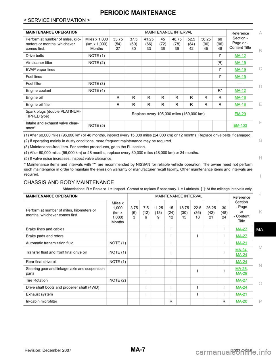
MAINTENANCE OPERATIONMAINTENANCE INTERVAL
Reference
Section -
Page or -
Content Title Perform at number of miles, kilo-
meters or months, whichever
comes first.Miles x 1,000
(km x 1,000)
Months3.75
(6)
37.50
(12)
611 . 2 5
(18)
915
(24)
1218.75
(30)
1522.5
(36)
1826.25
(42)
2130
(48)
24
Drive belts NOTE (1)MA-12
Air cleaner filter NOTE (2) [R]MA-15
EVAP vapor linesI*MA-19
Fuel linesI*MA-15
Fuel filter NOTE (3)—
Engine coolant NOTE (4)MA-12
Engine oil R R R R R R R RMA-16
Engine oil filter R R R R R R R RMA-16
Spark plugs (double PLATINUM-
TIPPED type)Replace every 105,000 miles (169,000 km).EM-29
Intake and exhaust valve clear-
ance*NOTE (5)EM-103
Page 2369 of 3061
PERIODIC MAINTENANCE
MA-7
< SERVICE INFORMATION >
C
D
E
F
G
H
I
J
K
MA
B
MA
N
O
P
(1) After 60,000 miles (96,000 km) or 48 months, inspect every 15,000 miles (24,000 km) or 12 months. Replace drive belts if damaged.
(2) If operating mainly in dusty conditions, more frequent maintenance may be required.
(3) Maintenance-free item. For service procedures, go to the FL section.
(4) After 60,000 miles (96,000 km) or 48 months, replace every 30,000 miles (48,000 km) or 24 months.
(5) If valve noise increases, inspect valve clearance.
* Maintenance items and intervals with “*” are recommended by NISSAN for reliable vehicle operation. The owner need not perform
such maintenance in order to maintain the emission warranty or manufacturer recall liability. Other maintenance items and intervals are
required.
CHASSIS AND BODY MAINTENANCE
Abbreviations: R = Replace. I = Inspect. Correct or replace if necessary. L = Lubricate. [ ]: At the mileage intervals only.
MAINTENANCE OPERATIONMAINTENANCE INTERVAL
Reference
Section -
Page or -
Content Title Perform at number of miles, kilo-
meters or months, whichever
comes first.Miles x 1,000
(km x 1,000)
Months33.75
(54)
2737.5
(60)
3041.25
(66)
3345
(72)
3648.75
(78)
3952.5
(84)
4256.25
(90)
4560
(96)
48
Drive belts NOTE (1) I*MA-12
Air cleaner filter NOTE (2) [R]MA-15
EVAP vapor linesI*MA-19
Fuel linesI*MA-15
Fuel filter NOTE (3)—
Engine coolant NOTE (4) R*MA-12
Engine oil R R R R R R R RMA-16
Engine oil filter R R R R R R R RMA-16
Spark plugs (double PLATINUM-
TIPPED type)Replace every 105,000 miles (169,000 km).EM-29
Intake and exhaust valve clear-
ance*NOTE (5)EM-103
MAINTENANCE OPERATIONMAINTENANCE INTERVAL
Reference
Section
- Page
or
- Content
Title Perform at number of miles, kilometers or
months, whichever comes first.Miles x
1,000
(km x
1,000)
Months3.75
(6)
37.5
(12)
611 . 2 5
(18)
915
(24)
1218.75
(30)
1522.5
(36)
1826.25
(42)
2130
(48)
24
Brake lines and cables I IMA-27
Brake pads and rotors I I I IMA-27
Automatic transmission fluid NOTE (1) I IMA-21
Transfer fluid and front final drive oil NOTE (1) I IMA-24,
MA-24
Rear final drive oil NOTE (1) I IMA-24
Steering gear and linkage, axle and suspension
partsII I IMA-28,
MA-29
Tire Rotation NOTE (2)MA-27
Drive shaft boots and propeller shaft (4WD) I I I IMA-24
Exhaust system I I I IMA-21
In-cabin microfilter R RMA-20
Page 2370 of 3061

MA-8
< SERVICE INFORMATION >
PERIODIC MAINTENANCE
(1) If towing a trailer, or using a car-top carrier, or driving on rough or muddy roads, change (not just inspect) oil at every 30,000 miles
(48,000 km) or 24 months.
(2) Refer to “Tire rotation” under the “General maintenance” heading earlier in this section.
Schedule 2INFOID:0000000003533863
EMISSION CONTROL SYSTEM MAINTENANCE
Abbreviations: R = Replace. I = Inspect. Correct or replace if necessary. [ ]: At the mileage intervals only
(1) After 60,000 miles (96,000 km) or 48 months, inspect every 15,000 miles (24,000 km) or 12 months. Replace drive belts if damaged.
(2) Maintenance-free item. For service procedures, go to FL section.
(3) After 60,000 miles (96,000 km) or 48 months, replace every 30,000 miles (48,000 km) or 24 months.
(4) If valve noise increases, inspect valve clearance.
* Maintenance items and intervals with “*” are recommended by NISSAN for reliable vehicle operation. The owner need not perform
such maintenance in order to maintain the emission warranty or manufacturer recall liability. Other maintenance items and intervals are
required.
CHASSIS AND BODY MAINTENANCE
MAINTENANCE OPERATIONMAINTENANCE INTERVAL
Reference
Section
- Page
or
- Content
Title Perform at number of miles, kilometers or
months, whichever comes first.Miles x
1,000
(km x
1,000)
Months33.75
(54)
2737.5
(60)
3041.25
(66)
3345
(72)
3648.75
(78)
3952.5
(84)
4256.25
(90)
4560
(96)
48
Brake lines and cables I IMA-27
Brake pads and rotors I I I IMA-27
Automatic transmission fluid NOTE (1) I IMA-21
Transfer fluid and front final drive oil NOTE (1) I IMA-24,
MA-24
Rear final drive oil NOTE (1) I IMA-24
Steering gear and linkage, axle and suspen-
sion partsIIIIMA-28,
MA-29
Tire Rotation NOTE (2)MA-27
Drive shaft boots and propeller shaft (4WD) I I I IMA-24
Exhaust system I I I IMA-21
In-cabin microfilter R RMA-20
MAINTENANCE OPERATIONMAINTENANCE INTERVAL
Reference
Section - Page
or - Content Ti-
tle Perform at number of miles, kilometers
or months, whichever comes first.Miles x 1,000
(km x 1,000)
Months7.5
(12)
615
(24)
1222.5
(36)
1830
(48)
2437.5
(60)
3045
(72)
3652.5
(84)
4260
(96)
48
Drive belts NOTE (1) I*MA-12
Air cleaner filter [R] [R]MA-15
EVAP vapor lines I* I*MA-19
Fuel lines I* I*MA-15
Fuel filter NOTE (2) —
Engine coolant NOTE (3) R*MA-12
Engine oil R R R R R R R RMA-16
Engine oil filter R R R R R R R RMA-16
Spark plugs (PLATINUM-TIPPED
type)Replace every 105,000 miles (169,000 km).EM-29
Intake and exhaust valve clearance* NOTE (4)EM-103
Page 2371 of 3061
![INFINITI QX56 2007 Factory Workshop Manual PERIODIC MAINTENANCE
MA-9
< SERVICE INFORMATION >
C
D
E
F
G
H
I
J
K
MA
B
MA
N
O
P
Abbreviations: R = Replace. I = Inspect. Correct or replace if necessary. L = Lubricate. [ ]: At the mileage interval INFINITI QX56 2007 Factory Workshop Manual PERIODIC MAINTENANCE
MA-9
< SERVICE INFORMATION >
C
D
E
F
G
H
I
J
K
MA
B
MA
N
O
P
Abbreviations: R = Replace. I = Inspect. Correct or replace if necessary. L = Lubricate. [ ]: At the mileage interval](/img/42/57029/w960_57029-2370.png)
PERIODIC MAINTENANCE
MA-9
< SERVICE INFORMATION >
C
D
E
F
G
H
I
J
K
MA
B
MA
N
O
P
Abbreviations: R = Replace. I = Inspect. Correct or replace if necessary. L = Lubricate. [ ]: At the mileage interval only.
(1) Refer to “Tire rotation” under the “General maintenance” heading earlier in this section. MAINTENANCE OPERATIONMAINTENANCE INTERVAL Reference
Section
- Page
or
- Content
Title Perform at number of miles, kilometers or
months, whichever comes first.Miles x 1,000
(km x 1,000)
Months7.5
(12)
615
(24)
1222.5
(36)
1830
(48)
2437.5
(60)
3045
(72)
3652.
5
(84)
4260
(96)
48
Brake lines and cables I I I IMA-27
Brake pads and rotors I I I IMA-27
Automatic transmission fluid I I I IMA-21
Transfer fluid and front final drive oil I I I IMA-24,
MA-24
Rear final drive oil I I I IMA-24
Steering gear and linkage, axle and suspen-
sion partsIIMA-28,
MA-29
Tire rotation NOTE (1)MA-27
Drive shaft boots and propeller shaft
(4WD)IIIIMA-24
Exhaust system I IMA-21
In-cabin microfilter R R R RMA-20
Page 2486 of 3061
REAR PROPELLER SHAFT
PR-9
< SERVICE INFORMATION >
C
E
F
G
H
I
J
K
L
MA
B
PR
N
O
P
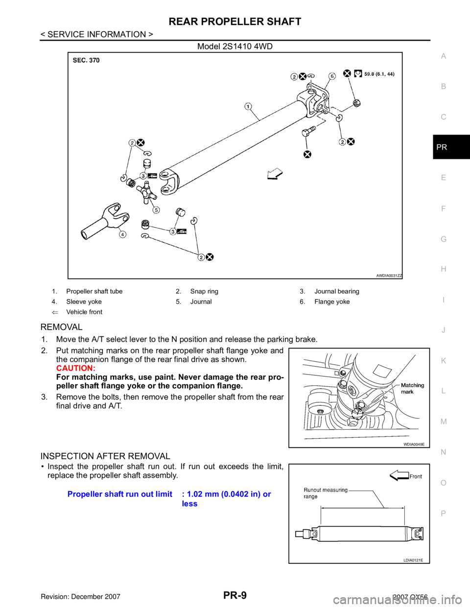
Model 2S1410 4WD
REMOVAL
1. Move the A/T select lever to the N position and release the parking brake.
2. Put matching marks on the rear propeller shaft flange yoke and
the companion flange of the rear final drive as shown.
CAUTION:
For matching marks, use paint. Never damage the rear pro-
peller shaft flange yoke or the companion flange.
3. Remove the bolts, then remove the propeller shaft from the rear
final drive and A/T.
INSPECTION AFTER REMOVAL
• Inspect the propeller shaft run out. If run out exceeds the limit,
replace the propeller shaft assembly.
AWDIA0031ZZ
1. Propeller shaft tube 2. Snap ring 3. Journal bearing
4. Sleeve yoke 5. Journal 6. Flange yoke
⇐Vehicle front
WDIA0049E
Propeller shaft run out limit : 1.02 mm (0.0402 in) or
less
LDIA0121E
Page 2490 of 3061
SERVICE DATA AND SPECIFICATIONS (SDS)
PR-13
< SERVICE INFORMATION >
C
E
F
G
H
I
J
K
L
MA
B
PR
N
O
P
SERVICE DATA AND SPECIFICATIONS (SDS)
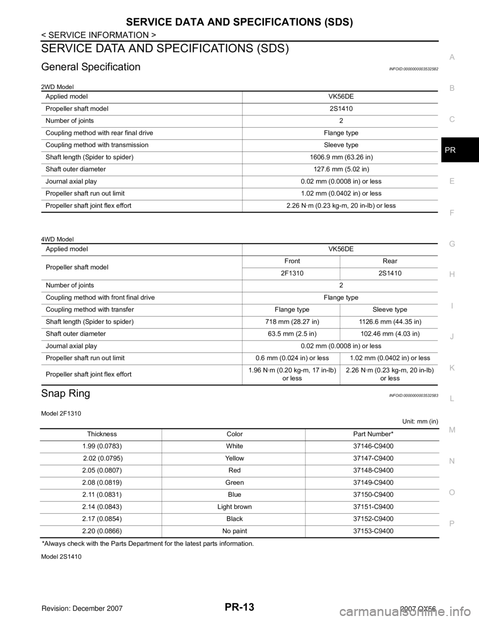
General SpecificationINFOID:0000000003532582
2WD Model
4WD Model
Snap RingINFOID:0000000003532583
Model 2F1310
Unit: mm (in)
*Always check with the Parts Department for the latest parts information.
Model 2S1410
Applied modelVK56DE
Propeller shaft model2S1410
Number of joints2
Coupling method with rear final drive Flange type
Coupling method with transmission Sleeve type
Shaft length (Spider to spider) 1606.9 mm (63.26 in)
Shaft outer diameter 127.6 mm (5.02 in)
Journal axial play 0.02 mm (0.0008 in) or less
Propeller shaft run out limit 1.02 mm (0.0402 in) or less
Propeller shaft joint flex effort 2.26 N·m (0.23 kg-m, 20 in-lb) or less
Applied modelVK56DE
Propeller shaft modelFront Rear
2F1310 2S1410
Number of joints2
Coupling method with front final drive Flange type
Coupling method with transfer Flange type Sleeve type
Shaft length (Spider to spider) 718 mm (28.27 in) 1126.6 mm (44.35 in)
Shaft outer diameter 63.5 mm (2.5 in) 102.46 mm (4.03 in)
Journal axial play 0.02 mm (0.0008 in) or less
Propeller shaft run out limit 0.6 mm (0.024 in) or less 1.02 mm (0.0402 in) or less
Propeller shaft joint flex effort1.96 N·m (0.20 kg-m, 17 in-lb)
or less2.26 N·m (0.23 kg-m, 20 in-lb)
or less
Thickness Color Part Number*
1.99 (0.0783) White 37146-C9400
2.02 (0.0795) Yellow 37147-C9400
2.05 (0.0807) Red 37148-C9400
2.08 (0.0819) Green 37149-C9400
2.11 (0.0831) Blue 37150-C9400
2.14 (0.0843) Light brown 37151-C9400
2.17 (0.0854) Black 37152-C9400
2.20 (0.0866) No paint 37153-C9400
Page 2506 of 3061
POWER STEERING GEAR AND LINKAGE
PS-15
< SERVICE INFORMATION >
C
D
E
F
H
I
J
K
L
MA
B
PS
N
O
P
POWER STEERING GEAR AND LINKAGE
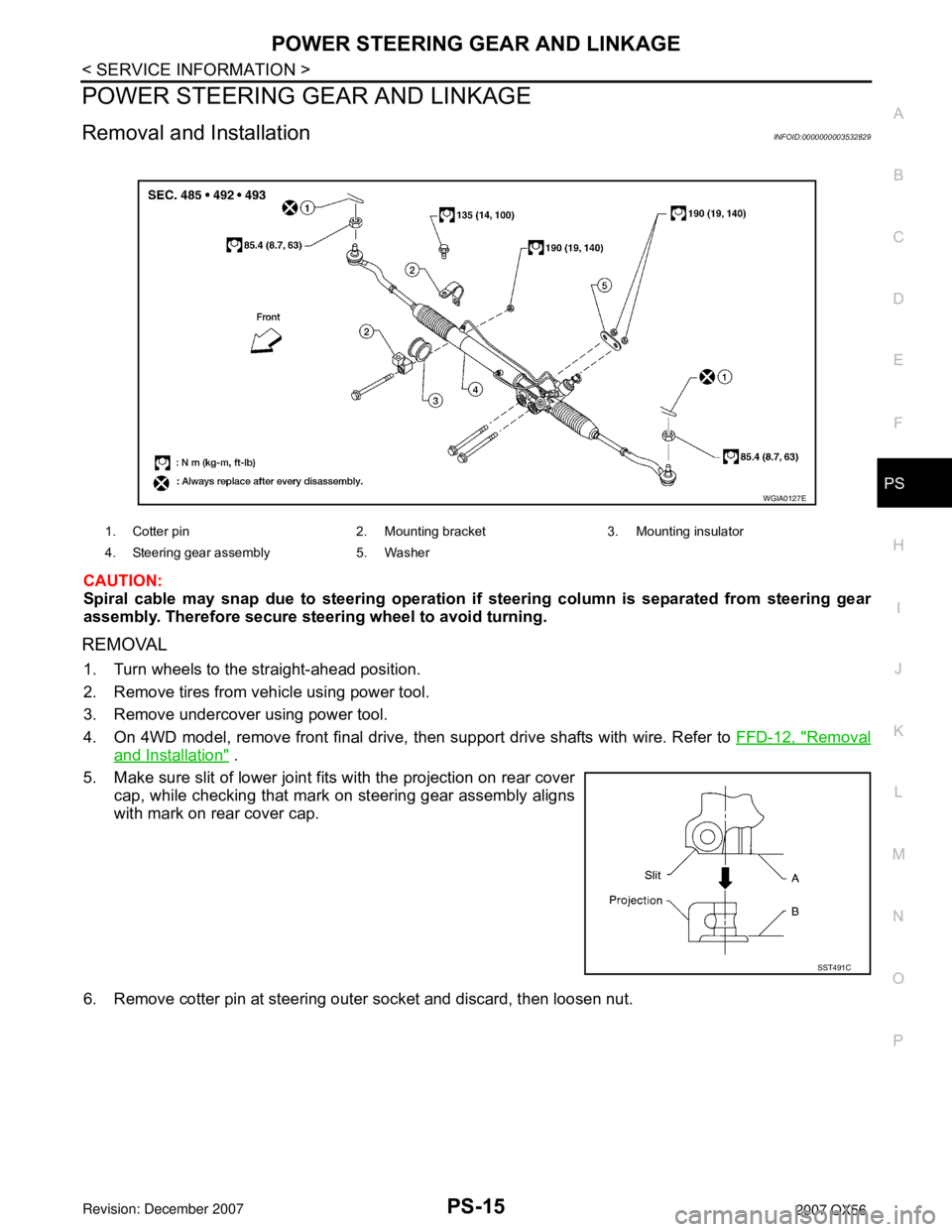
Removal and InstallationINFOID:0000000003532829
CAUTION:
Spiral cable may snap due to steering operation if steering column is separated from steering gear
assembly. Therefore secure steering wheel to avoid turning.
REMOVAL
1. Turn wheels to the straight-ahead position.
2. Remove tires from vehicle using power tool.
3. Remove undercover using power tool.
4. On 4WD model, remove front final drive, then support drive shafts with wire. Refer to FFD-12, "
Removal
and Installation" .
5. Make sure slit of lower joint fits with the projection on rear cover
cap, while checking that mark on steering gear assembly aligns
with mark on rear cover cap.
6. Remove cotter pin at steering outer socket and discard, then loosen nut.
1. Cotter pin 2. Mounting bracket 3. Mounting insulator
4. Steering gear assembly 5. Washer
WGIA0127E
SST491C
Page 2589 of 3061

RFD-32
< SERVICE INFORMATION >
SERVICE DATA AND SPECIFICATIONS (SDS)
SERVICE DATA AND SPECIFICATIONS (SDS)
General SpecificationINFOID:0000000003532608
Inspection and AdjustmentINFOID:0000000003532609
DRIVE GEAR RUNOUT
Unit: mm (in)
SIDE GEAR CLEARANCE
Unit: mm (in)
PRELOAD TORQUE
Unit: N·m (kg-m, in-lb)
BACKLASH
Unit: mm (in)
COMPANION FLANGE RUNOUT
Unit: mm (in)
SELECTIVE PARTS
Side Gear Thrust Washer
Applied modelVK56DE
2WD 4WD
Final drive modelR230
Gear ratio 2.937 3.357
Number of teeth (Drive gear/Drive pinion) 47 / 16 47 / 14
Oil capacity (Approx.)
1.75 (3 3/4 US pt, 3 1/8 Imp pt)
Number of pinion gears 2
Drive pinion adjustment spacer type Collapsible
Item Runout limit
Drive gear back face0.05 (0.0020) or less
Item Specification
Side gear back clearance
(Clearance limit between side gear and differential case for adjusting
side gear backlash)0.20 (0.0079) or less
(Each gear should rotate smoothly without excessive resis-
tance during differential motion.)
Item Specification
Drive pinion bearing preload torque 1.77 − 2.64 N·m (0.18 − 0.26 kg−m, 16 − 23 in-lb)
Side bearing preload torque (reference value determined by drive
gear bolt pulling force)0.20 − 0.52 N·m (0.02 − 0.05 kg−m, 2 − 4 in-lb)
Drive gear bolt pulling force (by spring gauge) 34.2 − 39.2 N (3.5 − 4 kg, 7.7 − 8.8 lb)
Total preload torque
(Total preload torque = drive pinion bearing preload torque + Side
bearing preload torque)2.05 − 4.11 N·m (0.21 − 0.42 kg−m, 19 − 36 in-lb)
Item Specification
Drive gear to drive pinion gear 0.13 − 0.18 (0.0051 − 0.0070)
Item Runout limit
Outer side of the companion flange 0.08 (0.0031) or less
Page 2634 of 3061
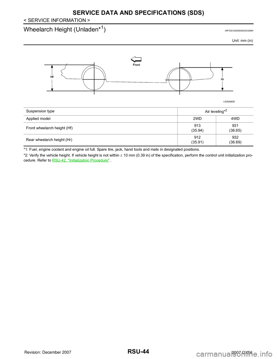
RSU-44
< SERVICE INFORMATION >
SERVICE DATA AND SPECIFICATIONS (SDS)
Wheelarch Height (Unladen*
1)INFOID:0000000003532684
Unit: mm (in)
*1: Fuel, engine coolant and engine oil full. Spare tire, jack, hand tools and mats in designated positions.
*2: Verify the vehicle height. If vehicle height is not within ± 10 mm (0.39 in) of the specification, perform the control unit initialization pro-
cedure. Refer to RSU-42, "
Initialization Procedure" . Suspension type
Air leveling*
2
Applied model2WD 4WD
Front wheelarch height (Hf)913
(35.94)931
(36.65)
Rear wheelarch height (Hr)912
(35.91)932
(36.69)
LEIA0085E
Page 2823 of 3061

TF-1
DRIVELINE/AXLE
C
E
F
G
H
I
J
K
L
M
SECTION TF
A
B
TF
N
O
P
CONTENTS
TRANSFER
SERVICE INFORMATION ............................3
PRECAUTIONS ...................................................3
Precaution for Supplemental Restraint System
(SRS) "AIR BAG" and "SEAT BELT PRE-TEN-
SIONER" ...................................................................
3
Precaution for Transfer Assembly and Transfer
Control Unit Replacement .........................................
3
Precaution .................................................................4
Service Notice ...........................................................4
PREPARATION ...................................................6
Special Service Tool .................................................6
Commercial Service Tool ..........................................9
NOISE, VIBRATION AND HARSHNESS
(NVH) TROUBLESHOOTING ............................
10
NVH Troubleshooting Chart ....................................10
TRANSFER FLUID .............................................11
Replacement ...........................................................11
Inspection ................................................................11
ALL-MODE 4WD SYSTEM ................................12
Cross-Sectional View ..............................................12
Power Transfer ........................................................12
System Description .................................................14
Schematic ...............................................................19
CAN Communication ...............................................20
TROUBLE DIAGNOSIS .....................................21
How to Perform Trouble Diagnosis .........................21
Location of Electrical Parts ......................................22
Circuit Diagram .......................................................23
Wiring Diagram - T/F - .............................................24
Inspections Before Trouble Diagnosis ....................31
Trouble Diagnosis Chart by Symptom ....................34
Transfer Control Unit Input/Output Signal Refer-
ence Value ..............................................................
35
CONSULT-II Function (ALL MODE AWD/4WD) .....42
Self-Diagnosis Procedure .......................................48
TROUBLE DIAGNOSIS FOR SYSTEM ............51
Power Supply Circuit for Transfer Control Unit ........51
Transfer Control Unit ...............................................53
Output Shaft Revolution Signal (TCM) ....................53
Vehicle Speed Sensor (ABS) ..................................54
Neutral-4LO Switch .................................................54
4WD Shift Switch .....................................................57
Wait Detection Switch ..............................................60
PNP Switch Signal (TCM) .......................................63
Actuator Motor .........................................................64
Actuator Position Switch ..........................................69
Transfer Control Device ...........................................72
Engine Speed Signal (ECM) ....................................76
Clutch Pressure Solenoid ........................................76
2-4WD Solenoid ......................................................80
Transfer Motor .........................................................84
Transfer Fluid Temperature .....................................90
Clutch Pressure Switch ...........................................92
Line Pressure Switch ...............................................94
Throttle Position Signal (ECM) ................................97
ABS Operation Signal (ABS) ...................................97
VDC Operation Signal (ABS) ...................................98
TCS Operation Signal (ABS) ...................................98
CAN Communication Line .......................................99
ATP Switch ..............................................................99
TROUBLE DIAGNOSIS FOR SYMPTOMS ....102
4WD Shift Indicator Lamp and 4LO Indicator
Lamp Do Not Turn ON ...........................................
102
4WD Warning Lamp Does Not Turn ON ...............104
4WD Shift Indicator Lamp or 4LO Indicator Lamp
Does Not Change ..................................................
107
ATP Warning Lamp Turns ON ...............................109
4LO Indicator Lamp Repeats Flashing ..................110
4WD Warning Lamp Flashes Rapidly ....................111
4WD Warning Lamp Flashes Slowly .....................112
Heavy Tight-corner Braking Symptom Occurs ......113
4WD System Does Not Operate ............................114
TRANSFER CONTROL UNIT .........................115
Removal and Installation .......................................115