Dlk INFINITI QX56 2009 Factory Service Manual
[x] Cancel search | Manufacturer: INFINITI, Model Year: 2009, Model line: QX56, Model: INFINITI QX56 2009Pages: 4171, PDF Size: 84.65 MB
Page 3414 of 4171
![INFINITI QX56 2009 Factory Service Manual SEC-104
< SYMPTOM DIAGNOSIS >[WITH INTELLIGENT KEY SYSTEM]
INTELLIGENT KEY SYSTEM/ENGIN
E START FUNCTION SYMPTOMS
SYMPTOM DIAGNOSIS
INTELLIGENT KEY SYSTEM/ENGINE START FUNCTION SYMPTOMS
Symptom TableI INFINITI QX56 2009 Factory Service Manual SEC-104
< SYMPTOM DIAGNOSIS >[WITH INTELLIGENT KEY SYSTEM]
INTELLIGENT KEY SYSTEM/ENGIN
E START FUNCTION SYMPTOMS
SYMPTOM DIAGNOSIS
INTELLIGENT KEY SYSTEM/ENGINE START FUNCTION SYMPTOMS
Symptom TableI](/img/42/57031/w960_57031-3413.png)
SEC-104
< SYMPTOM DIAGNOSIS >[WITH INTELLIGENT KEY SYSTEM]
INTELLIGENT KEY SYSTEM/ENGIN
E START FUNCTION SYMPTOMS
SYMPTOM DIAGNOSIS
INTELLIGENT KEY SYSTEM/ENGINE START FUNCTION SYMPTOMS
Symptom TableINFOID:0000000003775944
NOTE:
• Before performing the diagnosis in the following table, check “ SEC-3, "
Work Flow"”.
• Check that vehicle is under the condition shown in “Conditions of vehicle” before starting diagnosis, and check each symptom.
• Engine cranking is enabled when the shift lever is in the "Park" position, and in the "Neutral" position only if
the brake pedal is depressed.
• If the following symptoms are detected, check syst ems shown in the “Diagnosis/service procedure” column
in this order.
CONDITIONS OF VEHICLE (OPERATING CONDITIONS)
• Engine start function is ON when setting on CONSULT-III.
• Mechanical key is not inserted in key cylinder.
• One or more of Intelligent Keys with registered Intelligent Key ID is in the vehicle.
Symptom Diagnosis/service procedureReference
page
Ignition switch does not turn on with Intelligent Key.
[LCD displays "KEY DETECTED"] 1. Check steering lock solenoid.
DLK-99
2. Replace Intelligent Key unit.SEC-111
Ignition switch does not turn on with Intelligent Key.
[LCD does not display "PUSH" with arrow toward key
cylinder] 1. Check Intelligent Key unit power supply and ground circuit.
DLK-682. Check ignition knob switch.DLK-116
3. Check key switch (BCM input).DLK-115
4. Check key switch (Intelligent Key unit input).DLK-113
5. Replace Intelligent Key unit.SEC-111
Ignition switch does not turn on with Intelligent Key.
[LCD displays " NO KEY"]1a. Check inside key antenna 1 (rear of center console).
DLK-60
1b. Check inside key antenna 2 (luggage compartment).DLK-62
1c. Check inside key antenna 3 (front of center console).DLK-64
1d. Check inside key antenna 4 (overhead console area).DLK-68
2. Replace Intelligent Key unit.SEC-111
Ignition switch does not turn on with mechanical key1. Check key switch (BCM input).
DLK-1152. Check key switch (Intelligent Key unit input).DLK-113
Engine cannot be cranked with transmission in "Park"
or in "Neutral" position with brake pedal depressed.1. Check transmission signal.
TM-44
2. Check stop lamp switch.EXL-91
Revision: December 20092009 QX56
Page 3415 of 4171
![INFINITI QX56 2009 Factory Service Manual VEHICLE SECURITY SYSTEM SYMPTOMSSEC-105
< SYMPTOM DIAGNOSIS > [WITH INTELLIGENT KEY SYSTEM]
C
D
E
F
G H
I
J
L
M A
B
SEC
N
O P
VEHICLE SECURITY SYSTEM SYMPTOMS
Symptom TableINFOID:0000000003775945
*: C INFINITI QX56 2009 Factory Service Manual VEHICLE SECURITY SYSTEM SYMPTOMSSEC-105
< SYMPTOM DIAGNOSIS > [WITH INTELLIGENT KEY SYSTEM]
C
D
E
F
G H
I
J
L
M A
B
SEC
N
O P
VEHICLE SECURITY SYSTEM SYMPTOMS
Symptom TableINFOID:0000000003775945
*: C](/img/42/57031/w960_57031-3414.png)
VEHICLE SECURITY SYSTEM SYMPTOMSSEC-105
< SYMPTOM DIAGNOSIS > [WITH INTELLIGENT KEY SYSTEM]
C
D
E
F
G H
I
J
L
M A
B
SEC
N
O P
VEHICLE SECURITY SYSTEM SYMPTOMS
Symptom TableINFOID:0000000003775945
*: Check the system is in the armed phase. Procedure
Diagnostic procedure Refer to page
Symptom
1 Vehicle security sys-
tem cannot be set by
···· Door switch
Check door switch (LF, RF, LR, RR, back) DLK-71
Glass ajar switch Check glass ajar switch DLK-129
Hood switchCheck hood switch SEC-44
Intelligent Key Check Intelligent Key system DLK-106
Key cylinder switch Check key cylinder switch DLK-79
—Check Intermittent Incident GI-38
Security indicator does not turn ON.Check vehicle security indicator
SEC-47Check Intermittent Incident GI-38
2* Vehicle security
system does not
sound alarm when ···· Any door is opened. Check door switch (LF, RF, LR, RR, back)
DLK-71Glass hatch is opened Glass ajar switchDLK-129
Hood is opened Check hood switch SEC-44
—Check Intermittent Incident GI-38
3Vehicle security
alarm does not acti-
vate. Horn alarm Check horn switch
—
Check Intermittent Incident GI-38
4Vehicle security sys-
tem cannot be can-
celed by ···· Intelligent Key Check Intelligent Key system
DLK-106Key cylinder switch Check key cylinder switch DLK-79
—Check Intermittent Incident GI-38
Revision: December 20092009 QX56
Page 3417 of 4171
![INFINITI QX56 2009 Factory Service Manual PRE-INSPECTION FOR DIAGNOSTICSEC-107
< ON-VEHICLE MAINTENANCE > [WITH INTELLIGENT KEY SYSTEM]
C
D
E
F
G H
I
J
L
M A
B
SEC
N
O P
ON-VEHICLE MAINTENANCE
PRE-INSPECTION FOR DIAGNOSTIC
Basic InspectionINF INFINITI QX56 2009 Factory Service Manual PRE-INSPECTION FOR DIAGNOSTICSEC-107
< ON-VEHICLE MAINTENANCE > [WITH INTELLIGENT KEY SYSTEM]
C
D
E
F
G H
I
J
L
M A
B
SEC
N
O P
ON-VEHICLE MAINTENANCE
PRE-INSPECTION FOR DIAGNOSTIC
Basic InspectionINF](/img/42/57031/w960_57031-3416.png)
PRE-INSPECTION FOR DIAGNOSTICSEC-107
< ON-VEHICLE MAINTENANCE > [WITH INTELLIGENT KEY SYSTEM]
C
D
E
F
G H
I
J
L
M A
B
SEC
N
O P
ON-VEHICLE MAINTENANCE
PRE-INSPECTION FOR DIAGNOSTIC
Basic InspectionINFOID:0000000003775947
The engine start function, door lock function, power distribution system and NATS-IVIS/NMS in the Intelligent
Key system are closely related to each other regarding control. Narrow down the functional area in question
by performing basic inspection to i dentify which function is malfunctioning. The vehicle security function can
operate only when the door lock and power distribution system are operating normally. Therefore, it is easy to
identify any factor unique to the vehicle security system by performing the vehicle security operation check
after basic inspection.
1.CHECK DOOR LOCK OPERATION
Check the door lock for normal operation with the Intelligent Key controller and door request switch.
Successful door lock operation with the Intelligent Key and request SW indicates that the remote keyless entry
receiver and inside key antenna required for engine start are functioning normally.
Identify the malfunctioning point by referring to the DLK section if the door cannot be unlocked.
Can the door be locked with the Intelligent Key and door request switch?
YES >> GO TO 2.
NO >> Refer to DLK-206, "
Symptom Table".
2.CHECK ENGINE STARTING
Checks that the engine starts when operating the Intelligent Key.
Does the engine start?
YES >> GO TO 3.
NO >> Refer to SEC-104, "
Symptom Table".
3.CHECK STEERING LOCKING
Does the steering lock when operating door switch after switching the power supply from ON position (or ACC
position) to LOCK position?
If door switch is malfunctioning, BC M cannot lock the steering. If BCM does not detect DTC, steering lock unit
is normal.
Does steering lock?
YES >> GO TO 4.
NO >> Refer to DLK-71, "
ComponentFunctionCheck".
4.CHECK IGNITION KNOB SWITCH OPERATION
Press ignition knob to check switch operation.
Does the combination meter display any message?
YES >> GO TO 5.
NO >> Refer to SEC-42, "
Ignition Knob Switch Check".
5.CHECK VEHICLE SECURITY SYSTEM
Check the vehicle security system for normal operation.
The vehicle security function can operate only when t he door lock and power distribution functions are operat-
ing normally.
Therefore, it is easy to identify any factor unique to the vehicle security by performing the vehicle security
operation check after this basic inspection.
>> Go to SEC-107, "
Vehicle Security Operation Check".
Vehicle Security Operation CheckINFOID:0000000003775948
1.INSPECTION START
Turn ignition switch “OFF”.
NOTE:
Before starting operation check, open front windows.
Revision: December 20092009 QX56
Page 3418 of 4171
![INFINITI QX56 2009 Factory Service Manual SEC-108
< ON-VEHICLE MAINTENANCE >[WITH INTELLIGENT KEY SYSTEM]
PRE-INSPECTION FOR DIAGNOSTIC
>> GO TO 2.
2.CHECK SECURITY INDICATOR LAMP
1. Lock doors using Intelligent Key or mechanical key.
2. Chec INFINITI QX56 2009 Factory Service Manual SEC-108
< ON-VEHICLE MAINTENANCE >[WITH INTELLIGENT KEY SYSTEM]
PRE-INSPECTION FOR DIAGNOSTIC
>> GO TO 2.
2.CHECK SECURITY INDICATOR LAMP
1. Lock doors using Intelligent Key or mechanical key.
2. Chec](/img/42/57031/w960_57031-3417.png)
SEC-108
< ON-VEHICLE MAINTENANCE >[WITH INTELLIGENT KEY SYSTEM]
PRE-INSPECTION FOR DIAGNOSTIC
>> GO TO 2.
2.CHECK SECURITY INDICATOR LAMP
1. Lock doors using Intelligent Key or mechanical key.
2. Check that security indicator lamp illuminates for 30 seconds.
Security indicator lamp should illuminate.
OK >> GO TO 3.
NG >> Perform diagnosis and repair. Refer to SEC-47, "
ComponentFunctionCheck".
3.CHECK ALARM FUNCTION
1. After 30 seconds, security indicator lamp will start to blink.
2. Open any door or hood before unlocking with Intelligent Key or mechanical key, or open back door or glass hatch without the presence of Intelligent Key.
Does the alarm function properly?
YES >> GO TO 4.
NO >> Check the following. • The vehicle security system does not phase in alarm mode. Refer to SEC-105, "
Symptom
Table".
• Alarm (horn and headlamps) does not operate. Refer to SEC-105, "
Symptom Table".
4.CHECK ALARM CANCEL OPERATION
Unlock any door using Intelligent Key or mechanical key.
Alarm (horn and headlamps) should stop.
OK >> Inspection End.
NG >> Check door lock function. Refer to DLK-21, "
INTELLIGENT KEY : System Description".
Revision: December 20092009 QX56
Page 3987 of 4171

WCS-10
< FUNCTION DIAGNOSIS >
WARNING CHIME SYSTEM
KEY WARNING CHIME
KEY WARNING CHIME : System DiagramINFOID:0000000003776700
KEY WARNING CHIME : System DescriptionINFOID:0000000003776701
WHEN MECHANICAL KEY IS USED
With the key inserted into the key switch, and the ignition switch in the LOCK or ACC position, when driver's
door is opened, the warning chime will sound.
• BCM detects key inserted into the ignition switch, and sends key warning signal to combination meter with CAN communication line.
• When combination meter receives key warning signal, it sounds the warning chime.
WHEN INTELLIGENT KEY IS CARRIED WITH THE DRIVER
Refer to DLK-6, "Work Flow".
WKIA5464E
Revision: December 20092009 QX56
Page 4039 of 4171

WCS-62
< SYMPTOM DIAGNOSIS >
THE LIGHT REMINDER WARNING DOES NOT SOUND
SYMPTOM DIAGNOSIS
THE LIGHT REMINDER WARNING DOES NOT SOUND
DescriptionINFOID:0000000003776730
Light reminder warning does not sound even though headlamp is illuminated.
Diagnosis ProcedureINFOID:0000000003776731
1.CHECK COMBINATION SWITCH (LIGHTING SWITCH) OPERATION
Check that the headlamps operate normally by operat ing the combination switch (lighting switch).
Do they operate normally?
YES >> GO TO 2
NO >> Refer to EXL-4, "
Work Flow".
2.CHECK FRONT DOOR SWITCH LH SIGNAL CIRCUIT
Perform inspection of the front door s witch LH signal circuit. Refer to DLK-71, "
Diagnosis Procedure".
Is the inspection result normal?
YES >> GO TO 3
NO >> Repair harness or connector.
3.CHECK FRONT DOOR SWITCH LH
Perform a unit inspection for the front door switch LH. Refer to DLK-71, "
Diagnosis Procedure".
Is the inspection result normal?
YES >> Replace the BCM. Refer to BCS-56, "Removal and Installation".
NO >> Replace the front door switch LH.
Revision: December 20092009 QX56
Page 4100 of 4171

DIAGNOSIS SYSTEM (IPDM E/R)WW-13
< FUNCTION DIAGNOSIS >
C
DE
F
G H
I
J
K
M A
B
WW
N
O P
DIAGNOSIS SYSTEM (IPDM E/R)
Diagnosis DescriptionINFOID:0000000004115472
AUTO ACTIVE TEST
Description
In auto active test mode, the IPDM E/R sends a drive signal to the following systems to check their operation.
• Oil pressure low/coolant pressure high warning indicator
• Oil pressure gauge
• Rear window defogger
• Front wipers
• Tail, license and parking lamps
• Front fog lamps
• Headlamps (Hi, Lo)
• A/C compressor (magnetic clutch)
• Cooling fan
Operation Procedure
1. Close the hood and front door RH, and lift the wiper arms from the windshield (to prevent windshield dam-
age due to wiper operation).
NOTE:
When auto active test is performed with hood opened, sprinkle water on windshield before hand.
2. Turn ignition switch OFF.
3. Turn the ignition switch ON and, within 20 seconds, press the front door switch LH 10 times. Then turn the ignition switch OFF.
4. Turn the ignition switch ON within 10 seconds. Af ter that the horn sounds once and the auto active test
starts.
5. After a series of the following operations is repeated 3 times, auto active test is completed.
NOTE:
When auto active test mode has to be cancelled halfway through test, turn ignition switch OFF.
CAUTION:
• If auto active test mode cannot be actua ted, check door switch system. Refer to DLK-71,
"ComponentFunctionCheck".
• Do not start the engine.
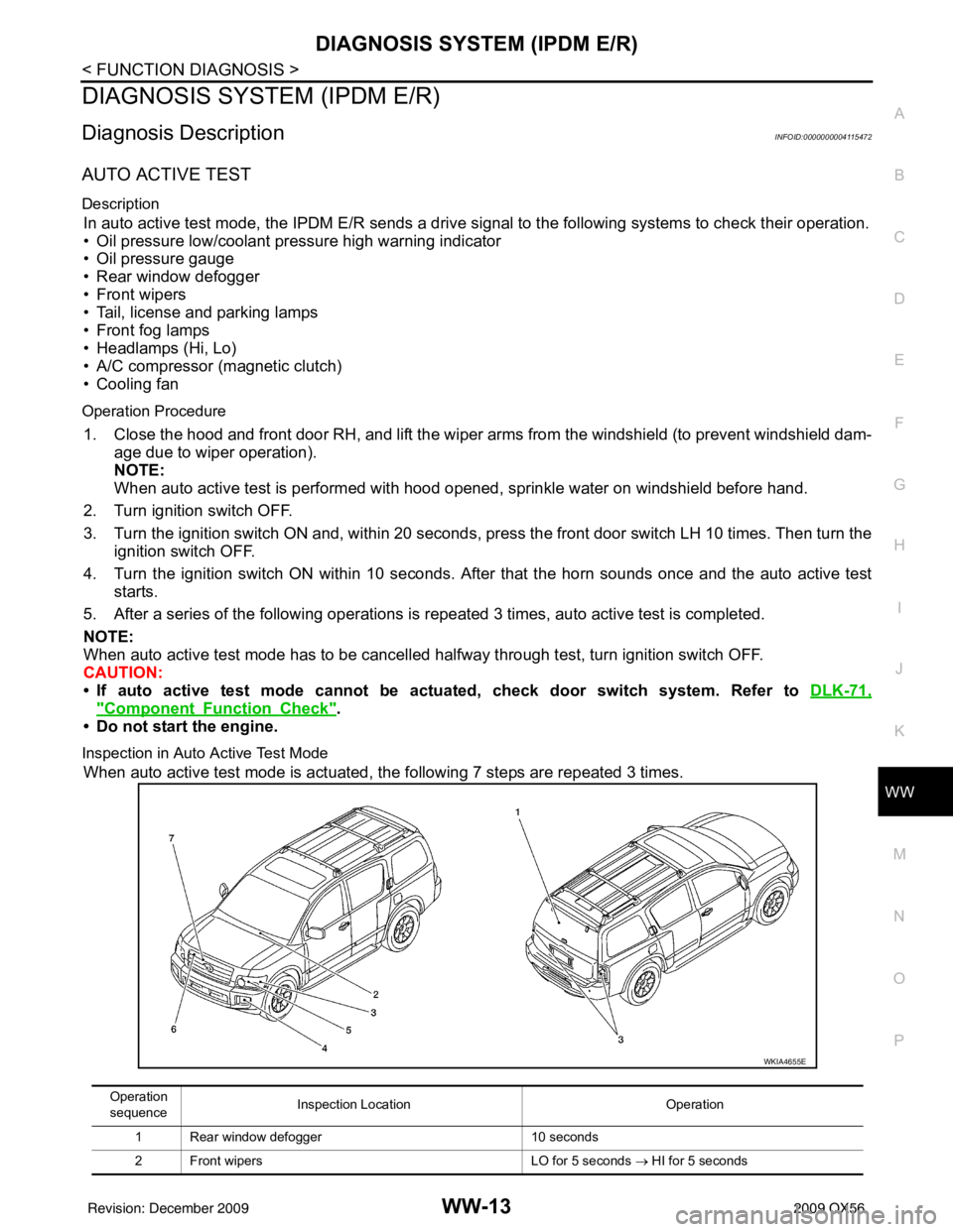
Inspection in Auto Active Test Mode
When auto active test mode is actuated, the following 7 steps are repeated 3 times.
Operation
sequence Inspection Location
Operation
1 Rear window defogger 10 seconds
2 Front wipers LO for 5 seconds → HI for 5 seconds
WKIA4655E
Revision: December 20092009 QX56
Page 4116 of 4171

REAR WIPER MOTOR CIRCUITWW-29
< COMPONENT DIAGNOSIS >
C
DE
F
G H
I
J
K
M A
B
WW
N
O P
3. Make sure hatch glass is closed
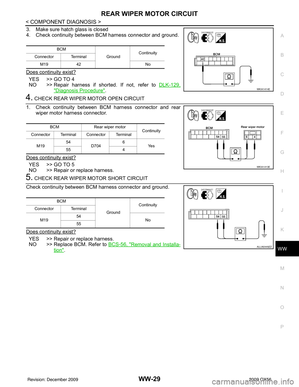
4. Check continuity between BCM harness connector and ground.
Does continuity exist?
YES >> GO TO 4
NO >> Repair harness if shorted. If not, refer to DLK-129,
"Diagnosis Procedure".
4. CHECK REAR WIPER MOTOR OPEN CIRCUIT
1. Check continuity between BCM harness connector and rear wiper motor harness connector.
Does continuity exist?
YES >> GO TO 5
NO >> Repair or replace harness.
5. CHECK REAR WIPER MOTOR SHORT CIRCUIT
Check continuity between BCM harness connector and ground.
Does continuity exist?
YES >> Repair or replace harness.
NO >> Replace BCM. Refer to BCS-56, "
Removal and Installa-
tion".
BCM
GroundContinuity
Connector Terminal
M19 42 No
WKIA1414E
BCMRear wiper motor
Continuity
Connector Terminal Connector Terminal
M19 54
D704 6
Ye s
55 4
WKIA1413E
BCM
GroundContinuity
Connector Terminal
M19 54
No
55
ALLIA0449ZZ
Revision: December 20092009 QX56
Page 4169 of 4171

WW-82
< ON-VEHICLE REPAIR >
REAR WIPER AND WASHER SYSTEM
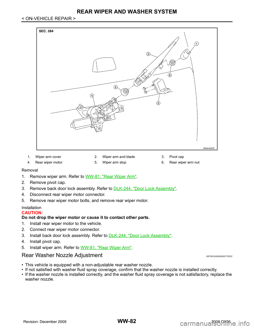
Removal
1. Remove wiper arm. Refer to WW-81, "Rear Wiper Arm".
2. Remove pivot cap.
3. Remove back door lock assembly. Refer to DLK-244, "
Door Lock Assembly".
4. Disconnect rear wiper motor connector.
5. Remove rear wiper motor bolts, and remove rear wiper motor.
Installation
CAUTION:
Do not drop the wiper motor or cause it to contact other parts.
1. Install rear wiper motor to the vehicle.
2. Connect rear wiper motor connector.
3. Install back door lock assembly. Refer to DLK-244, "
Door Lock Assembly".
4. Install pivot cap.
5. Install wiper arm. Refer to WW-81, "
Rear Wiper Arm".
Rear Washer Nozzle AdjustmentINFOID:0000000003776322
• This vehicle is equipped with a non-adjustable rear washer nozzle.
• If not satisfied with washer fluid spray coverage, c onfirm that the washer nozzle is installed correctly.
• If the washer nozzle is installed correctly, and the washer fluid spray coverage is not satisfactory, replace the
washer nozzle.
WKIA4567E
1. Wiper arm cover 2. Wiper arm and blade 3. Pivot cap
4. Rear wiper motor 5. Wiper arm stop6. Rear wiper arm nut
Revision: December 20092009 QX56