air condition INFINITI QX56 2010 Factory Service Manual
[x] Cancel search | Manufacturer: INFINITI, Model Year: 2010, Model line: QX56, Model: INFINITI QX56 2010Pages: 4210, PDF Size: 81.91 MB
Page 1850 of 4210
![INFINITI QX56 2010 Factory Service Manual SERVICE DATA AND SPECIFICATIONS (SDS)EC-497
< SERVICE DATA AND SPECIFICATIONS (SDS) [VK56DE]
C
D
E
F
G H
I
J
K L
M A
EC
NP
O
SERVICE DATA AND SPECIFICATIONS (SDS)
SERVICE DATA AND SPECIFICATIONS (SDS INFINITI QX56 2010 Factory Service Manual SERVICE DATA AND SPECIFICATIONS (SDS)EC-497
< SERVICE DATA AND SPECIFICATIONS (SDS) [VK56DE]
C
D
E
F
G H
I
J
K L
M A
EC
NP
O
SERVICE DATA AND SPECIFICATIONS (SDS)
SERVICE DATA AND SPECIFICATIONS (SDS](/img/42/57032/w960_57032-1849.png)
SERVICE DATA AND SPECIFICATIONS (SDS)EC-497
< SERVICE DATA AND SPECIFICATIONS (SDS) [VK56DE]
C
D
E
F
G H
I
J
K L
M A
EC
NP
O
SERVICE DATA AND SPECIFICATIONS (SDS)
SERVICE DATA AND SPECIFICATIONS (SDS)
Fuel PressureINFOID:0000000005149516
Idle Speed and Ignition TimingINFOID:0000000005149517
*: Under the following conditions:
• Air conditioner switch: OFF
• Electric load: OFF (Lights and heater fan)
• Steering wheel: Kept in straight-ahead position
Calculated Load ValueINFOID:0000000005149518
Mass Air Flow SensorINFOID:0000000005149519
*: Engine is warmed up to normal operating temperature and running under no load.
Intake Air Temperature SensorINFOID:0000000005149520
Engine Coolant Temperature SensorINFOID:0000000005149521
A/F Sensor 1 HeaterINFOID:0000000005149522
Fuel pressure at idling kPa (kg/cm2, psi)
Approximately 350 (3.57, 51)
Target idle speed
No-load* (in P or N position) 650±50 rpm
Air conditioner: ON In P or N position 700 rpm or more
Ignition timing In P or N position 15° ± 5 ° BTDC
Condition Calculated load value % (Using CONSULT-IIl or GST)
At idle 14.0 - 33.0
At 2,500 rpm 12.0 - 25.0
Supply voltageBattery voltage (11 - 14V)
Output voltage at idle 1.0 - 1.3V*
Mass air flow (Using CONSULT-IIl or GST) 3.0 - 9.0 g·m/sec at idle*
9.0 - 28.0 g·m/sec at 2,500 rpm*
Temperature °C ( °F) Resistance kΩ
25 (77) 1.800 - 2.200
Temperature °C ( °F) Resistance kΩ
20 (68) 2.1 - 2.9
50 (122) 0.68 - 1.00
90 (194) 0.236 - 0.260
Resistance [at 25°C (77 °F)] 1.98 - 2.66Ω
Revision: April 20092010 QX56
Page 1862 of 4210
NOISE, VIBRATION, AND HARSHNESS (NVH) TROUBLESHOOTINGEM-11
< FUNCTION DIAGNOSIS >
C
DE
F
G H
I
J
K L
M A
EM
NP
O
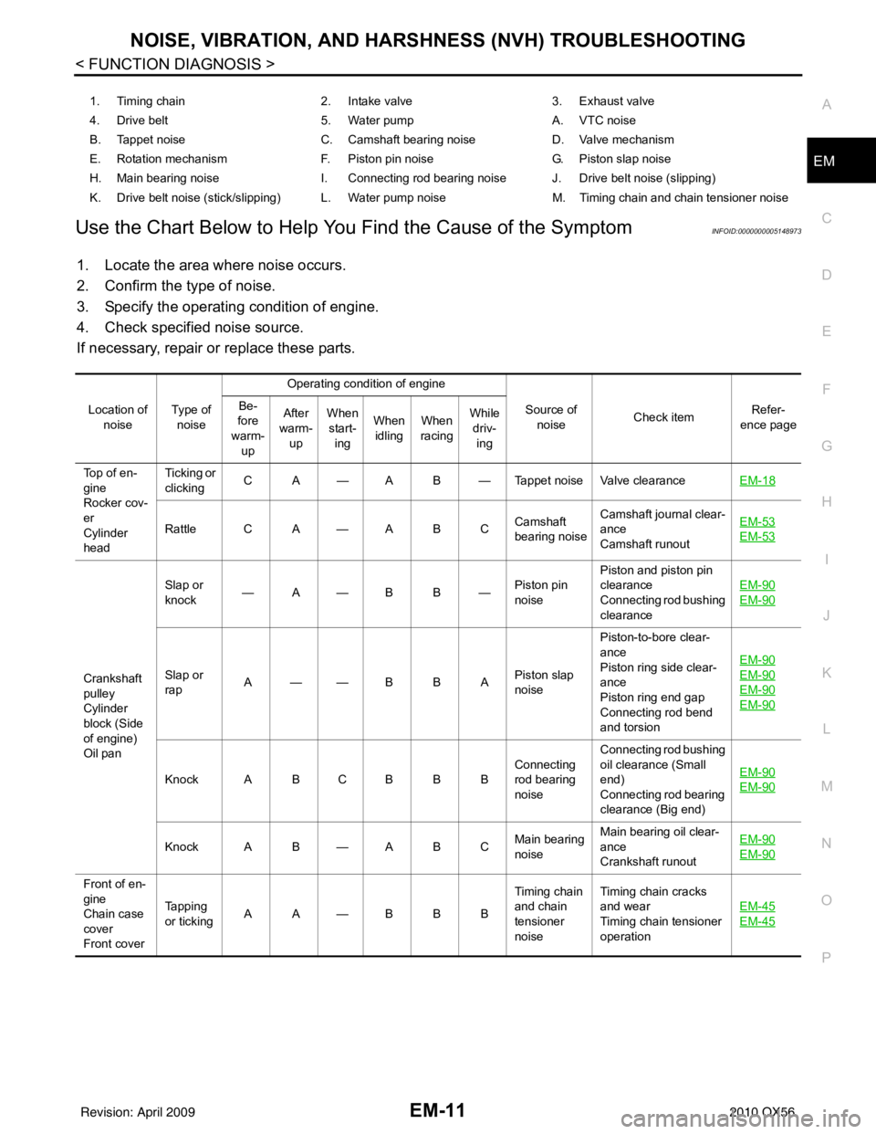
Use the Chart Below to Help You
Find the Cause of the SymptomINFOID:0000000005148973
1. Locate the area where noise occurs.
2. Confirm the type of noise.
3. Specify the operating condition of engine.
4. Check specified noise source.
If necessary, repair or replace these parts.
1. Timing chain 2. Intake valve3. Exhaust valve
4. Drive belt 5. Water pumpA. VTC noise
B. Tappet noise C. Camshaft bearing noiseD. Valve mechanism
E. Rotation mechanism F. Piston pin noise G. Piston slap noise
H. Main bearing noise I. Connecting rod bearing noise J. Drive belt noise (slipping)
K. Drive belt noise (stick/slipping) L. Water pump noise M. Timing chain and chain tensioner noise
Location of noise Ty p e o f
noise Operating condition of engine
Source of noise Check item Refer-
ence page
Be-
fore
warm-
up After
warm- up When
start- ing When
idling When
racing While
driv- ing
Top of en-
gine
Rocker cov-
er
Cylinder
head Ticking or
clicking
C A — A B — Tappet noise Valve clearance
EM-18
Rattle C A — A B CCamshaft
bearing noiseCamshaft journal clear-
ance
Camshaft runout EM-53EM-53
Crankshaft
pulley
Cylinder
block (Side
of engine)
Oil panSlap or
knock
—A—B B—
Piston pin
noisePiston and piston pin
clearance
Connecting rod bushing
clearance
EM-90
EM-90
Slap or
rap
A——B B A
Piston slap
noisePiston-to-bore clear-
ance
Piston ring side clear-
ance
Piston ring end gap
Connecting rod bend
and torsion EM-90EM-90
EM-90
EM-90
Knock A B C B B B
Connecting
rod bearing
noiseConnecting rod bushing
oil clearance (Small
end)
Connecting rod bearing
clearance (Big end)
EM-90EM-90
Knock A B — A B C
Main bearing
noiseMain bearing oil clear-
ance
Crankshaft runout EM-90EM-90
Front of en-
gine
Chain case
cover
Front coverTapping
or ticking
AA—BBB Timing chain
and chain
tensioner
noiseTiming chain cracks
and wear
Timing chain tensioner
operation
EM-45
EM-45
Revision: April 20092010 QX56
Page 1869 of 4210
EM-18
< ON-VEHICLE MAINTENANCE >
CAMSHAFT VALVE CLEARANCE
CAMSHAFT VALVE CLEARANCE
Valve ClearanceINFOID:0000000005148982
INSPECTION
NOTE:
Perform the following inspection after removal, installation or replacement of camshaft or valve-related parts,
or if there are unusual engine conditions due to changes in valve clearance over time (starting, idling, and/or
noise).
1. Warm up the engine. Then stop the engine.
2. Remove the engine room cover. Refer to EM-24, "
Removal and Installation".
3. Remove the air cleaner and air duct assembly. Refer to EM-25, "
Removal and Installation".
4. Remove the RH bank and LH bank rocker covers using power tool. Refer to EM-38, "
Removal and Instal-
lation".
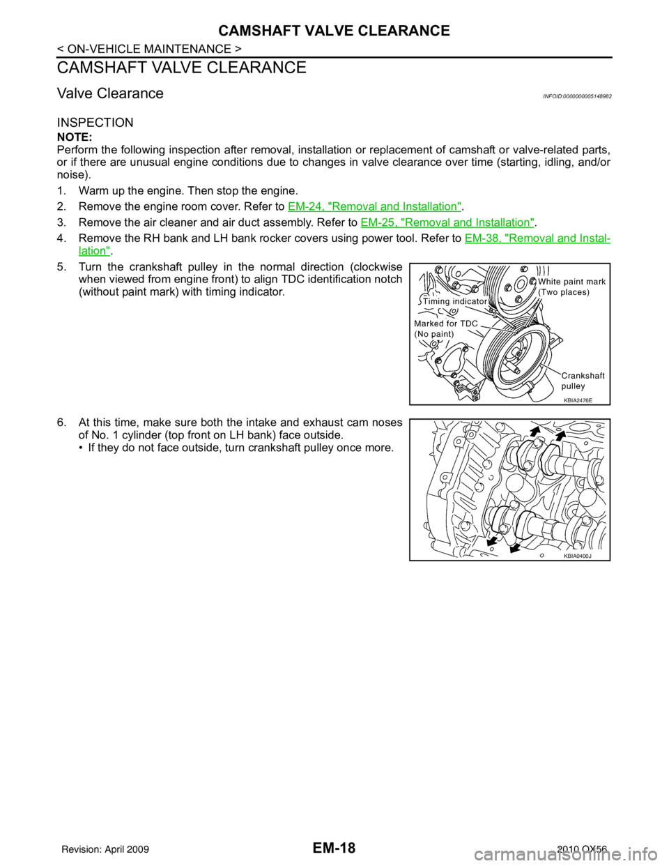
5. Turn the crankshaft pulley in the normal direction (clockwise when viewed from engine front) to align TDC identification notch
(without paint mark) with timing indicator.
6. At this time, make sure both the intake and exhaust cam noses of No. 1 cylinder (top front on LH bank) face outside.
• If they do not face outside, turn crankshaft pulley once more.
KBIA2476E
KBIA0400J
Revision: April 20092010 QX56
Page 1907 of 4210
EM-56
< ON-VEHICLE REPAIR >
CAMSHAFT
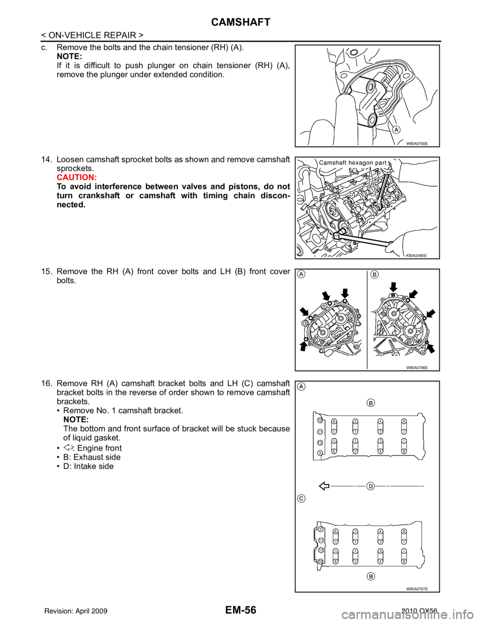
c. Remove the bolts and the chain tensioner (RH) (A).NOTE:
If it is difficult to push plunger on chain tensioner (RH) (A),
remove the plunger under extended condition.
14. Loosen camshaft sprocket bolts as shown and remove camshaft sprockets.
CAUTION:
To avoid interference between valves and pistons, do not
turn crankshaft or camshaft with timing chain discon-
nected.
15. Remove the RH (A) front cover bolts and LH (B) front cover bolts.
16. Remove RH (A) camshaft bracket bolts and LH (C) camshaft bracket bolts in the reverse of order shown to remove camshaft
brackets.
• Remove No. 1 camshaft bracket.NOTE:
The bottom and front surface of bracket will be stuck because
of liquid gasket.
• : Engine front
• B: Exhaust side
• D: Intake side
WBIA0705E
KBIA2485E
WBIA0706E
WBIA0707E
Revision: April 20092010 QX56
Page 1926 of 4210
CYLINDER HEADEM-75
< ON-VEHICLE REPAIR >
C
DE
F
G H
I
J
K L
M A
EM
NP
O
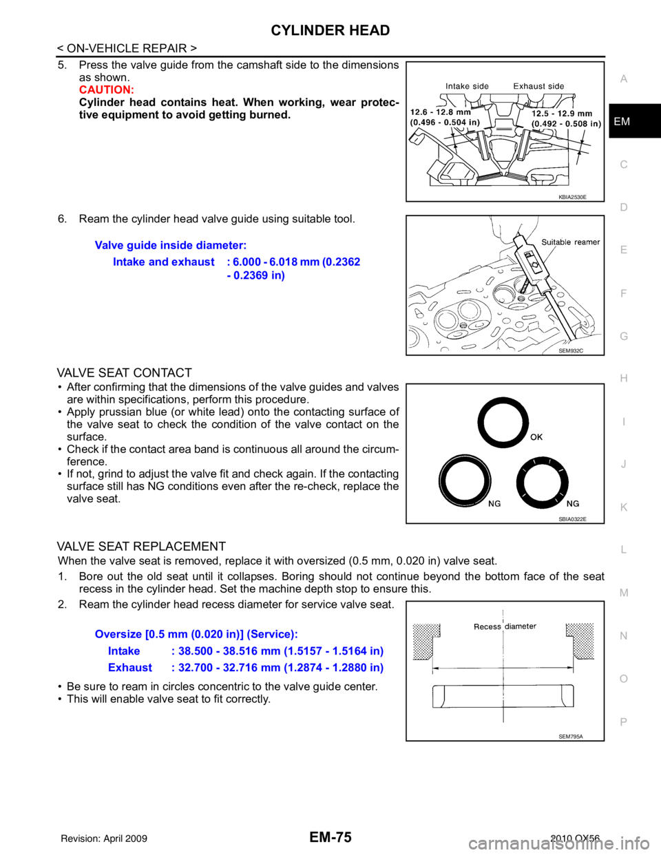
5. Press the valve guide from the camshaft side to the dimensions
as shown.
CAUTION:
Cylinder head contains heat . When working, wear protec-
tive equipment to avo id getting burned.
6. Ream the cylinder head valve guide using suitable tool.
VALVE SEAT CONTACT
• After confirming that the dimensions of the valve guides and valves are within specifications, perform this procedure.
• Apply prussian blue (or white lead) onto the contacting surface of the valve seat to check the condition of the valve contact on the
surface.
• Check if the contact area band is continuous all around the circum- ference.
• If not, grind to adjust the valve fi t and check again. If the contacting
surface still has NG conditions even after the re-check, replace the
valve seat.
VALVE SEAT REPLACEMENT
When the valve seat is removed, replace it with oversized (0.5 mm, 0.020 in) valve seat.
1. Bore out the old seat until it collapses. Boring should not continue beyond the bottom face of the seat recess in the cylinder head. Set the machine depth stop to ensure this.
2. Ream the cylinder head recess diameter for service valve seat.
• Be sure to ream in circles concentric to the valve guide center.
• This will enable valve seat to fit correctly.
KBIA2530E
Valve guide inside diameter:
Intake and exhaust : 6.000 - 6.018 mm (0.2362 - 0.2369 in)
SEM932C
SBIA0322E
Oversize [0.5 mm (0.020 in)] (Service):
Intake : 38.500 - 38.516 mm (1.5157 - 1.5164 in)
Exhaust : 32.700 - 32.716 mm (1.2874 - 1.2880 in)
SEM795A
Revision: April 20092010 QX56
Page 1952 of 4210
HOW TO SELECT PISTON AND BEARINGEM-101
< DISASSEMBLY AND ASSEMBLY >
C
DE
F
G H
I
J
K L
M A
EM
NP
O
HOW TO SELECT PISTON AND BEARING
How to Select Piston and BearingINFOID:0000000005149017
DESCRIPTION
*For the service parts, the grade for fitting cannot be selected between a piston pin and a connecting rod.
(Only 0 grade is available.) The information at the sh
ipment from the plant is described as a reference.
• The identification grade stamped on each part is the grade for the dimension measured in new condition.
This grade cannot apply to reused parts.
• For reused or repaired parts, measure the dimens ion accurately. Determine the grade by comparing the
measurement with the values of each selection table.
• For details of the measurement method of each part , the reuse standards, and the selection method of the
selective fitting parts, follow the applicable procedures.
HOW TO SELECT PISTON
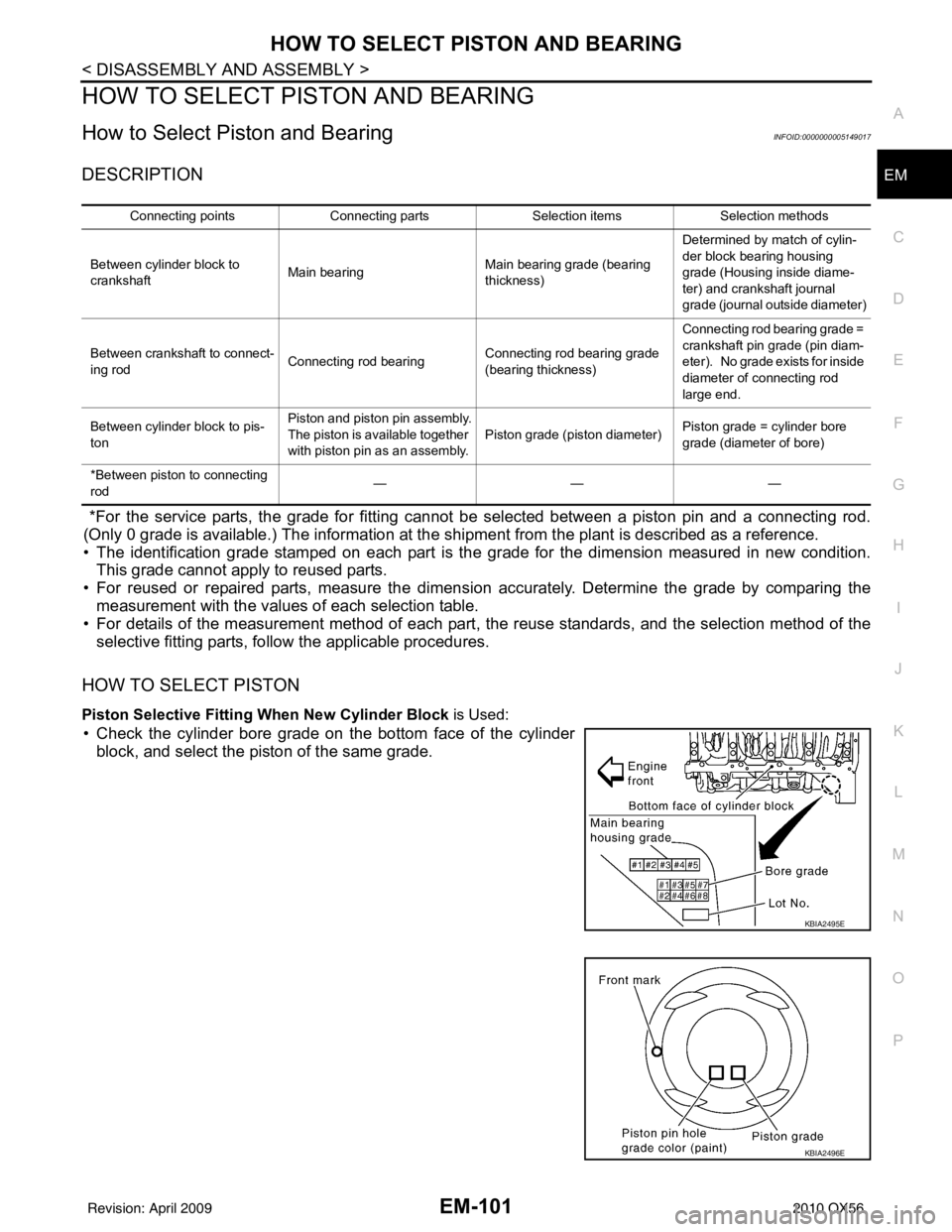
Piston Selective Fitting When New Cylinder Block is Used:
• Check the cylinder bore grade on the bottom face of the cylinder
block, and select the piston of the same grade.
Connecting points Connecting parts Selection itemsSelection methods
Between cylinder block to
crankshaft Main bearing Main bearing grade (bearing
thickness)Determined by match of cylin-
der block bearing housing
grade (Housing inside diame-
ter) and crankshaft journal
grade (journal outside diameter)
Between crankshaft to connect-
ing rod Connecting rod bearing Connecting rod bearing grade
(bearing thickness)Connecting rod bearing grade =
crankshaft pin grade (pin diam-
eter). No grade exists for inside
diameter of connecting rod
large end.
Between cylinder block to pis-
ton Piston and piston pin assembly.
The piston is available together
with piston pin as an assembly.
Piston grade (piston diameter)
Piston grade = cylinder bore
grade (diameter of bore)
*Between piston to connecting
rod ———
KBIA2495E
KBIA2496E
Revision: April 20092010 QX56
Page 2003 of 4210
POWER SUPPLY AND GROUND CIRCUITEXL-27
< COMPONENT DIAGNOSIS >
C
DE
F
G H
I
J
K
M A
B
EXL
N
O P
COMPONENT DIAGNOSIS
POWER SUPPLY AND GROUND CIRCUIT
BCM (BODY CONTROL MODULE)
BCM (BODY CONTROL MODULE) : Diagnosis ProcedureINFOID:0000000005369888
Regarding Wiring Diagram information, refer to BCS-49, "Wiring Diagram".
1. CHECK FUSES AND FUSIBLE LINK
Check that the following fuses and fusible link are not blown.
Is the fuse blown?
YES >> Replace the blown fuse or fusible link after repairing the affected circuit.
NO >> GO TO 2
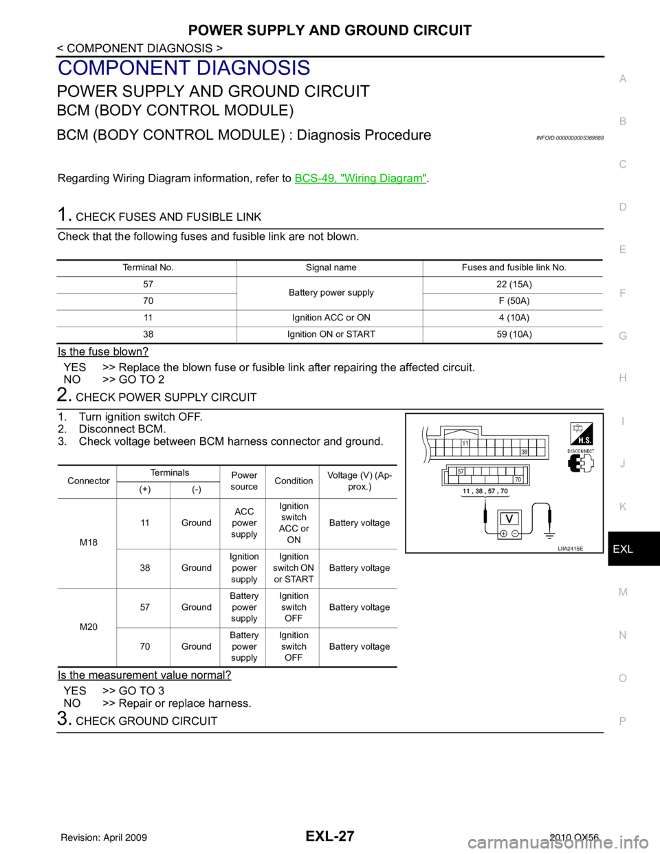
2. CHECK POWER SUPPLY CIRCUIT
1. Turn ignition switch OFF.
2. Disconnect BCM.
3. Check voltage between BCM harness connector and ground.
Is the measurement value normal?
YES >> GO TO 3
NO >> Repair or replace harness.
3. CHECK GROUND CIRCUIT
Terminal No. Signal nameFuses and fusible link No.
57 Battery power supply 22 (15A)
70 F (50A)
11 Ignition ACC or ON 4 (10A)
38 Ignition ON or START 59 (10A)
ConnectorTe r m i n a l s
Power
source Condition Voltage (V) (Ap-
prox.)
(+) (-)
M18 11 Ground
ACC
power
supply Ignition
switch
ACC or ON Battery voltage
38 Ground Ignition
power
supply Ignition
switch ON
or START Battery voltage
M20 57 Ground
Battery
power
supply Ignition
switch OFF Battery voltage
70 Ground Battery
power
supply Ignition
switch OFF Battery voltage
LIIA2415E
Revision: April 20092010 QX56
Page 2023 of 4210
OPTICAL SENSOREXL-47
< COMPONENT DIAGNOSIS >
C
DE
F
G H
I
J
K
M A
B
EXL
N
O P
OPTICAL SENSOR
DescriptionINFOID:0000000005146657
The optical sensor converts the outside brightness (lux) to voltage and transmits the optical sensor signal to
the BCM.
Component Function CheckINFOID:0000000005146658
1.CHECK OPTICAL SENSOR SIGNAL BY CONSULT-III
CONSULT-III
1. Turn the ignition switch ON.
2. Select "OPTICAL SENSOR" of BC M (HEAD LAMP) DATA MONITOR item.
3. Turn the lighting switch to AUTO.
4. With the optical sensor illuminat ing, check the monitor status.
*: Illuminates the optical sensor. The value may be less than the standard value if brightness is weak.
Is the item status normal?
YES >> Optical sensor is normal.
NO >> Refer to EXL-47, "
Diagnosis Procedure".
Diagnosis ProcedureINFOID:0000000005146659
Regarding Wiring Diagram information, refer to EXL-62, "Wiring Diagram".
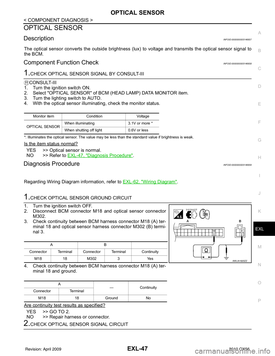
1.CHECK OPTICAL SENSOR GROUND CIRCUIT
1. Turn the ignition switch OFF.
2. Disconnect BCM connector M18 and optical sensor connector M302.
3. Check continuity between BCM harness connector M18 (A) ter-
minal 18 and optical sensor harness connector M302 (B) termi-
nal 3.
4. Check continuity between BCM harness connector M18 (A) ter- minal 18 and ground.
Are continuity test results as specified?
YES >> GO TO 2.
NO >> Repair harness or connector.
2.CHECK OPTICAL SENSOR SIGNAL CIRCUIT
Monitor item ConditionVoltage
OPTICAL SENSOR When illuminating
3.1V or more *
When shutting off light 0.6V or less
AB
Connector Terminal Connector Terminal Continuity M181 8M3023 Y es
A —Contin u it y
Connector Terminal
M18 18Ground No
AWLIA1620ZZ
Revision: April 20092010 QX56
Page 2082 of 4210

EXL-106
< ECU DIAGNOSIS >
BCM (BODY CONTROL MODULE)
ECU DIAGNOSIS
BCM (BODY CONTROL MODULE)
Reference ValueINFOID:0000000005369890
VALUES ON THE DIAGNOSIS TOOL
Monitor ItemCondition Value/Status
AIR COND SW A/C switch OFF
OFF
A/C switch ON ON
AUT LIGHT SYS Outside of the room is dark
OFF
Outside of the room is bright ON
AUTO LIGHT SW Lighting switch OFF
OFF
Lighting switch AUTO ON
BACK DOOR SW Back door closed
OFF
Back door opened ON
CARGO LAMP SW Cargo lamp switch OFF
OFF
Cargo lamp switch ON ON
CDL LOCK SW Door lock/unlock switch does not operate
OFF
Press door lock/unlock switch to the LOCK side ON
CDL UNLOCK SW Door lock/unlock switch does not operate
OFF
Press door lock/unlock switch to the UNLOCK side ON
DOOR SW-AS Front door RH closed
OFF
Front door RH opened ON
DOOR SW-DR Front door LH closed
OFF
Front door LH opened ON
DOOR SW-RL Rear door LH closed
OFF
Rear door LH opened ON
DOOR SW-RR Rear door RH closed
OFF
Rear door RH opened ON
ENGINE RUN Engine stopped
OFF
Engine running ON
FR FOG SW Front fog lamp switch OFF
OFF
Front fog lamp switch ON ON
FR WASHER SW Front washer switch OFF
OFF
Front washer switch ON ON
FR WIPER LOW Front wiper switch OFF
OFF
Front wiper switch LO ON
FR WIPER HI Front wiper switch OFF
OFF
Front wiper switch HI ON
FR WIPER INT Front wiper switch OFF
OFF
Front wiper switch INT ON
FR WIPER STOP Any position other than front wiper stop position
OFF
Front wiper stop position ON
HAZARD SW When hazard switch is not pressed
OFF
When hazard switch is pressed ON
Revision: April 20092010 QX56
Page 2098 of 4210

EXL-122
< ECU DIAGNOSIS >
IPDM E/R (INTELLIGENT POWER DISTRIBUTION MODULE ENGINE ROOM)
IPDM E/R (INTELLIGENT POWER DISTRIBUTION MODULE ENGINE
ROOM)
Reference ValueINFOID:0000000005369897
VALUES ON THE DIAGNOSIS TOOL
Monitor Item ConditionValue/Status
MOTOR FAN REQ Engine idle speed Changes depending on engine
coolant temperature, air conditioner
operation status, vehicle speed,
etc.0 - 100 %
A/C COMP REQ A/C switch OFF
OFF
A/C switch ON ON
TAIL&CLR REQ Lighting switch OFF
OFF
Lighting switch 1ST, 2ND, HI or AUTO (Light is illuminated) ON
HL LO REQ Lighting switch OFF
OFF
Lighting switch 2ND HI or AUTO (Light is illuminated) ON
HL HI REQ Lighting switch OFF
OFF
Lighting switch HI ON
FR FOG REQ Lighting switch 2ND or AUTO (Light
is illuminated) Front fog lamp switch OFF OFF
• Front fog lamp switch ON
• Daytime light activated (Canada
only) ON
FR WIP REQ Ignition switch ON Front wiper switch OFF
STOP
Front wiper switch INT 1LOW
Front wiper switch LO LOW
Front wiper switch HI HI
WIP AUTO STOP Ignition switch ON Front wiper stop position
STOP P
Any position other than front wiper
stop position ACT P
WIP PROT Ignition switch ON Front wiper operates normally OFF
Front wiper stops at fail-safe opera-
tion
BLOCK
ST RLY REQ Ignition switch OFF or ACC
OFF
Ignition switch START ON
IGN RLY Ignition switch OFF or ACC
OFF
Ignition switch ON ON
RR DEF REQ Rear defogger switch OFF
OFF
Rear defogger switch ON ON
OIL P SW Ignition switch OFF, ACC or engine running
OPEN
Ignition switch ON CLOSE
DTRL REQ Daytime light system requested OFF with CONSULT-III.
OFF
Daytime light system requested ON with CONSULT-III. ON
HOOD SW Hood closed.
OFF
Hood open. ON
Revision: April 20092010 QX56