height INFINITI QX56 2011 Factory Service Manual
[x] Cancel search | Manufacturer: INFINITI, Model Year: 2011, Model line: QX56, Model: INFINITI QX56 2011Pages: 5598, PDF Size: 94.53 MB
Page 2961 of 5598

UPPER LINKFSU-19
< REMOVAL AND INSTALLATION >
C
DF
G H
I
J
K L
M A
B
FSU
N
O P
4. Adjust levelizer adjustment of height sensor. Refer to EXL-61, "LEVELIZER ADJUSTMENT : Special
Repair Requirement".
Revision: 2010 May2011 QX56
Page 2963 of 5598

SERVICE DATA AND SPECIFICATIONS (SDS)
FSU-21
< SERVICE DATA AND SPECIFICATIONS (SDS)
C
D F
G H
I
J
K L
M A
B
FSU
N
O P
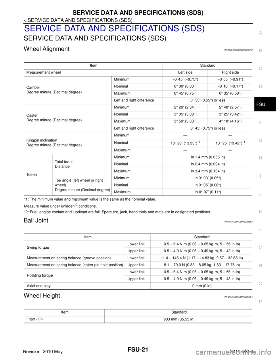
SERVICE DATA AND SPECIFICATIONS (SDS)
SERVICE DATA AND SPECIFICATIONS (SDS)
Wheel AlignmentINFOID:0000000006225652
*1: The minimum value and maximum value is the same as the nominal value.
Measure value under unladen
*2 conditions.
*2: Fuel, engine coolant and lubricant are full. Spare tire, jack, hand tools and mats are in designated positions.
Ball JointINFOID:0000000006225653
Wheel HeightINFOID:0000000006225654
Item Standard
Measurement wheel Left side Right side
Camber
Degree minute (Decimal degree) Minimum
−0 °45 ′ ( −0.75 °) −0°55 ′ ( −0.91 °)
Nominal 0 ° 00 ′ (0.00 °) −0°10 ′ ( −0.17 °)
Maximum 0 ° 45 ′ (0.75 °)0 ° 35 ′ (0.58 °)
Left and right difference 0 ° 33 ′ (0.55 °) or less
Caster
Degree minute (Decimal degree) Minimum 2
° 20 ′ (2.34 °)2 ° 40 ′ (2.67 °)
Nominal 3 ° 05 ′ (3.08 °)3 ° 25 ′ (3.42 °)
Maximum 3 ° 50 ′ (3.83 °)4 ° 10 ′ (4.16
° )
Left and right difference 0 ° 45 ′ (0.75 °) or less
Kingpin inclination
Degree minute (Decimal degree) Minimum — —
Nominal
13° 20 ′ (13.33 °)
*113 ° 25 ′ (13.42 °)*1
Maximum — —
To e - i n To t a l t o e - i n
Distance
Minimum In 1.4 mm (0.055 in)
Nominal In 2.4 mm (0.094 in)
Maximum In 3.4 mm (0.134 in)
Toe angle (left wheel or right
wheel)
Degree minute (Decimal degree) Minimum In 0
° 03 ′ (0.05 °)
Nominal In 0 ° 05 ′ (0.08 °)
Maximum In 0 ° 07 ′ (0.11 °)
Item Standard
Swing torque Lower link 0.5 – 6.4 N·m (0.06 – 0.65 kg-m, 5 – 56 in-lb)
Upper link 0.5 – 4.9 N·m (0.06 – 0.49 kg-m, 5 – 43 in-lb)
Measurement on spring balance (groove position) Lower link 11.4 – 145.4 N (1.17 – 14.83 kg, 2.57 – 32.68 lb)
Measurement on spring balance (cotter pin hole position) Upper link 8.1 – 79.0 N (0.83 – 8.05 kg, 1.83 – 17.75 lb)
Rotating torque Lower link 0.5 – 6.4 N·m (0.06 – 0.65 kg-m, 5 – 56 in-lb)
Upper link 0.5 – 4.9 N·m (0.06 – 0.49 kg-m, 5 – 43 in-lb)
Axial end play 0 mm (0 in)
Item Standard
Front (Hf) 903 mm (35.55 in)
Revision: 2010 May2011 QX56
Page 2989 of 5598

IDENTIFICATION INFORMATIONGI-25
< VEHICLE INFORMATION >
C
DE
F
G H
I
J
K L
M B
GI
N
O P
DimensionsINFOID:0000000006280863
Unit: mm (in)
Wheels & TiresINFOID:0000000006280864
: Vehicle front
JPAIA0770ZZ
Overall length 5,290 (208.3)
Overall width 2,030 (79.9)
Overall height 1,925 (75.8)
Front tread 1,715 (67.5)
Rear tread 1,725 (67.9)
Wheelbase 3,075 (121.1)
ConventionalTire
20 inch P275/60R20 114H
22 inch P275/50R22 111H
Road wheel 20 inch
(Aluminum)
Size 20
× 8J
Offset 30 mm (1.18 in)
22 inch
(Aluminum) Size 22
× 8J
Offset 30 mm (1.18 in)
Spare Tire
20 inch P275/60R20 114H
22 inch P275/50R22 111H
Road wheel 20 inch
(Aluminum)
Size 20
× 8J
Offset 30 mm (1.18 in)
22 inch
(Aluminum) Size 22
× 8J
Offset 30 mm (1.18 in)
Revision: 2010 May2011 QX56
Page 3813 of 5598

MWI-70
< DTC/CIRCUIT DIAGNOSIS >
FUEL LEVEL SENSOR SIGNAL CIRCUIT
Is the inspection result normal?
YES >> GO TO 3.
NO >> Repair harness or connector.
3.CHECK FUEL LEVEL SENSOR GROUND CIRCUIT
Check continuity between fuel level sensor unit harness connector and combination meter harness connector.
Is the inspection result normal?
YES >> INSPECTION END
NO >> Repair harness or connector.
Component InspectionINFOID:0000000006221750
1.REMOVE FUEL LEVEL SENSOR UNIT
Remove the fuel level sensor unit. Refer to FL-5, "
Removal and Installation".
>> GO TO 2.
2.CHECK FUEL LEVEL SENSOR UNIT
Check the resistance between fuel level sensor unit and fuel pump.
*: When float rod is contact with stopper.
Is inspection result OK?
YES >> INSPECTION END
NO >> Replace fuel level sensor unit and fuel pump. Refer to FL-5, "
Removal and Installation".
Combination meter
GroundContinuity
Connector Terminal
M34 34 Not existed
Fuel level sensor unit Combination meter Continuity
Connector Terminal Connector Terminal
C5 5 M34 24 Existed
Te r m i n a l s ConditionResistance (
Ω)
(Approx.) Height [mm (in)]
Fuel level sensor unit
25 Full
* (A)
46.0 282 (11.10)
Empty
* (B) 278.0 29 (1.14)
JSNIA3018ZZ
Revision: 2010 May2011 QX56
Page 4204 of 5598

RAX-8
< REMOVAL AND INSTALLATION >
REAR WHEEL HUB AND HOUSING
b. Using suitable tool, rotate adjuster (1) in the direction (A) toretract and loosen brake shoe.
5. Remove wheel sensor harness. Refer to BRC-135, "
REAR
WHEEL SENSOR : Removal and Installation".
6. Remove parking brake shoe and parking brake cable from back plate. Refer to PB-7, "
Removal and Installation" and PB-5,
"Removal and Installation".
7. Remove height sensor from rear lower link (right side). Refer to EXL-136, "
Removal and Installation".
8. Remove vehicle height sensor from rear lower link (left side). Refer to SCS-98, "
Removal and Installation".
9. Set suitable jack under rear lower link.
10. Remove rear lower link from axle housing. Refer to RSU-8, "
Removal and Installation".
11. Remove coil spring. Refer to RSU-8, "
Removal and Installation".
12. Remove cotter pin and adjusting cap, then loosen wheel hub lock nut.
13. Put matching mark (A) on drive shaft and wheel hub and bearing assembly.
CAUTION:
Use paint or similar substance for matching marks. Never
scratch the surface.
14. Patch wheel hub lock nut with a piece of wood. Hammer the wood to disengage wheel hub and bearing assembly from drive
shaft.
CAUTION:
Never place drive shaft joint at an extreme angle. Also be
careful not to over extend slide joint.
Never allow drive shaft to ha ng down without support for
counterpart such as joint sub-assembly, and other parts.
NOTE:
Use a suitable puller, if wheel hub and bearing assembly and drive shaft cannot be separated even after
performing the above procedure.
15. Remove wheel hub lock nut.
16. Remove suspension arm from axle housing. CAUTION:
Never damage ball joint boot.
17. Remove front lower link from axle housing. CAUTION:
Never damage ball joint boot.
18. Remove axle housing.
19. Remove wheel hub and bearing assembly.
20. Remove anchor block mounting nuts, and then remove anchor block and back plate from axle housing.
21. Remove hub bolts (1) from wheel hub and bearing assembly, using the ball joint remover (A) (commercial service tool).
CAUTION:
Remove hub bolt only when necessary.
Never hammer the hub bolt to avoid impact to the wheel
hub and bearing assembly.
Pull out the hub bolt in a direction perpendicular to the wheel hub and bearing assembly.
22. Perform inspection after removal. Refer to RAX-9, "
Inspection".
INSTALLATION
Note the following, and install in the reverse order of removal.
JPFIB0014ZZ
JPDIG0121ZZ
JPDIF0299ZZ
Revision: 2010 May2011 QX56
Page 4206 of 5598

RAX-10
< REMOVAL AND INSTALLATION >
REAR WHEEL HUB AND HOUSING
4. Adjust levelizer adjustment of height sensor. Refer to EXL-61, "LEVELIZER ADJUSTMENT : Special
Repair Requirement".
5. Check standard vehicle height setting of vehicle height sensor. Refer to SCS-67, "
Work Procedure".
Revision: 2010 May2011 QX56
Page 4207 of 5598

REAR DRIVE SHAFTRAX-11
< REMOVAL AND INSTALLATION >
CEF
G H
I
J
K L
M A
B
RAX
N
O P
REAR DRIVE SHAFT
Exploded ViewINFOID:0000000006225468
Removal and InstallationINFOID:0000000006225469
REMOVAL
1. Remove tire.
2. Remove parking brake cable from suspension member. Refer to PB-5, "
Removal and Installation".
3. Remove wheel sensor harness. Refer to BRC-135, "
REAR WHEEL SENSOR : Removal and Installation".
4. Remove height sensor from rear lower link (right side). Refer to EXL-136, "
Removal and Installation".
5. Remove vehicle height sensor from rear lower link (left side). Refer to SCS-98, "
Removal and Installa-
tion".
6. Set suitable jack under rear lower link.
7. Remove rear lower link (axle housing side). Refer to RSU-8, "
Removal and Installation".
8. Remove coil spring. Refer to RSU-8, "
Removal and Installation".
9. Remove cotter pin and adjusting cap, then loosen wheel hub lock nut. Refer to RAX-7, "
Removal and
Installation".
1. Housing 2. Snap ring 3. Ball cage/steel ball/inner race as-
sembly
4. Stopper ring 5. Boot band 6. Boot
7. Shaft 8. Circular clip 9. Joint sub-assembly
10. Dust shield : Wheel side
1: NISSAN genuine grease or an equivalent.
2: Apply paste [service parts (440037S000)].
Refer to GI-4, "
Components" for symbols not described on the above.
JPDIG0164GB
Revision: 2010 May2011 QX56
Page 4213 of 5598

REAR DRIVE SHAFTRAX-17
< REMOVAL AND INSTALLATION >
CEF
G H
I
J
K L
M A
B
RAX
N
O P
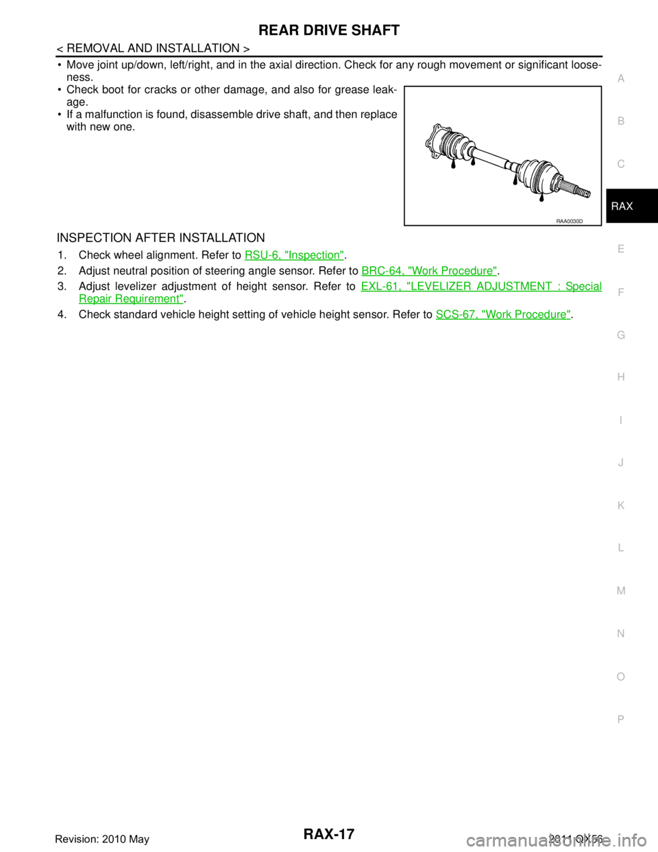
Move joint up/down, left/right, and in the axial directi on. Check for any rough movement or significant loose-
ness.
Check boot for cracks or other damage, and also for grease leak-
age.
If a malfunction is found, disassem ble drive shaft, and then replace
with new one.
INSPECTION AFTER INSTALLATION
1. Check wheel alignment. Refer to RSU-6, "Inspection".
2. Adjust neutral position of steering angle sensor. Refer to BRC-64, "
Work Procedure".
3. Adjust levelizer adjustment of height sensor. Refer to EXL-61, "
LEVELIZER ADJUSTMENT : Special
Repair Requirement".
4. Check standard vehicle height setting of vehicle height sensor. Refer to SCS-67, "
Work Procedure".
RAA0030D
Revision: 2010 May2011 QX56
Page 4247 of 5598

GLASS LIDRF-33
< REMOVAL AND INSTALLATION >
C
DE
F
G H
I
J
L
M A
B
RF
N
O P
Removal and InstallationINFOID:0000000006141246
CAUTION:
Always work with a helper.
Fully close the glass lid, before removal, th en never operate sunroof motor after removal.
REMOVAL
1. Remove the side trims (LH, RH).
2. Remove the TORX bolts (A) and remove glass lid.
INSTALLATION
CAUTION:
After installing the glass lid, perform the leak test and check the there is no malfunction.
NOTE:
After installation carry out fitting adjustment. Refer to RF-33, "
Adjustment".
Install in the reverse order of removal.
AdjustmentINFOID:0000000006141247
Glass lid Adjustment and Surface Mismatch Adjustment
1. Remove side trims.
2. After loosening glass lid from TORX bolts (left and right).
3. Adjust glass lid from outside of vehicle so it resembles “A – A”,“B – B”“C – C”.
JMKIA0029ZZ
JMKIA5137ZZ
1. Roof panel 2. Glass lid
Portion a (Clearance) b (S urface height difference)
A – A 0.6 – 2.2 mm (0.024 – 0.087 in) −
1.5) – (+1.5) mm
[( −0.059) – (+0.059) in]
Revision: 2010 May2011 QX56
Page 4256 of 5598

RSU-1
SUSPENSION
C
DF
G H
I
J
K L
M
SECTION RSU
A
B
RSU
N
O PCONTENTS
REAR SUSPENSION
PRECAUTION ................ ...............................2
PRECAUTIONS .............................................. .....2
Precautions for Suspension ................................ ......2
PREPARATION ............................................3
PREPARATION .............................................. .....3
Special Service Tools .......................................... ......3
Commercial Service Tools ........................................3
SYMPTOM DIAGNOSIS ...............................4
NOISE, VIBRATION AND HARSHNESS
(NVH) TROUBLESHOOTING ........................ .....
4
NVH Troubleshooting Chart ................................ ......4
PERIODIC MAINTENANCE ..........................5
REAR SUSPENSION ASSEMBLY ................ .....5
Inspection ............................................................ ......5
WHEEL ALIGNMENT ..........................................6
Inspection ............................................................ ......6
Adjustment ................................................................6
REMOVAL AND INSTALLATION ................8
REAR LOWER LINK & COIL SPRING .......... .....8
Exploded View .................................................... ......8
Removal and Installation ...........................................8
Inspection ..................................................................9
REAR SHOCK ABSORBER ..............................10
Exploded View .................................................... ....10
Removal and Installation ..................................... ....10
Inspection and Adjustment ......................................11
Disposal ...................................................................12
SUSPENSION ARM ..........................................13
Exploded View .........................................................13
Removal and Installation .........................................13
Inspection and Adjustment ......................................13
FRONT LOWER LINK .......................................15
Exploded View .........................................................15
Removal and Installation .........................................15
Inspection ................................................................15
REAR STABILIZER ..........................................17
Exploded View .........................................................17
Removal and Installation .........................................17
Inspection ................................................................17
UNIT REMOVAL AND INSTALLATION ......18
REAR SUSPENSION MEMBER .......................18
Exploded View ..................................................... ....18
Removal and Installation .........................................18
Inspection and Adjustment ......................................19
SERVICE DATA AND SPECIFICATIONS
(SDS) ............... .............................................
20
SERVICE DATA AND SPECIFICATIONS
(SDS) .................................................................
20
Wheel Alignment ................................................. ....20
Ball Joint ..................................................................20
Wheel Height ...........................................................20
Revision: 2010 May2011 QX56