center console INFINITI QX56 2011 Factory Owner's Guide
[x] Cancel search | Manufacturer: INFINITI, Model Year: 2011, Model line: QX56, Model: INFINITI QX56 2011Pages: 5598, PDF Size: 94.53 MB
Page 3413 of 5598
CENTER CONSOLE ASSEMBLYIP-23
< REMOVAL AND INSTALLATION >
C
DE
F
G H
I
K L
M A
B
IP
N
O P
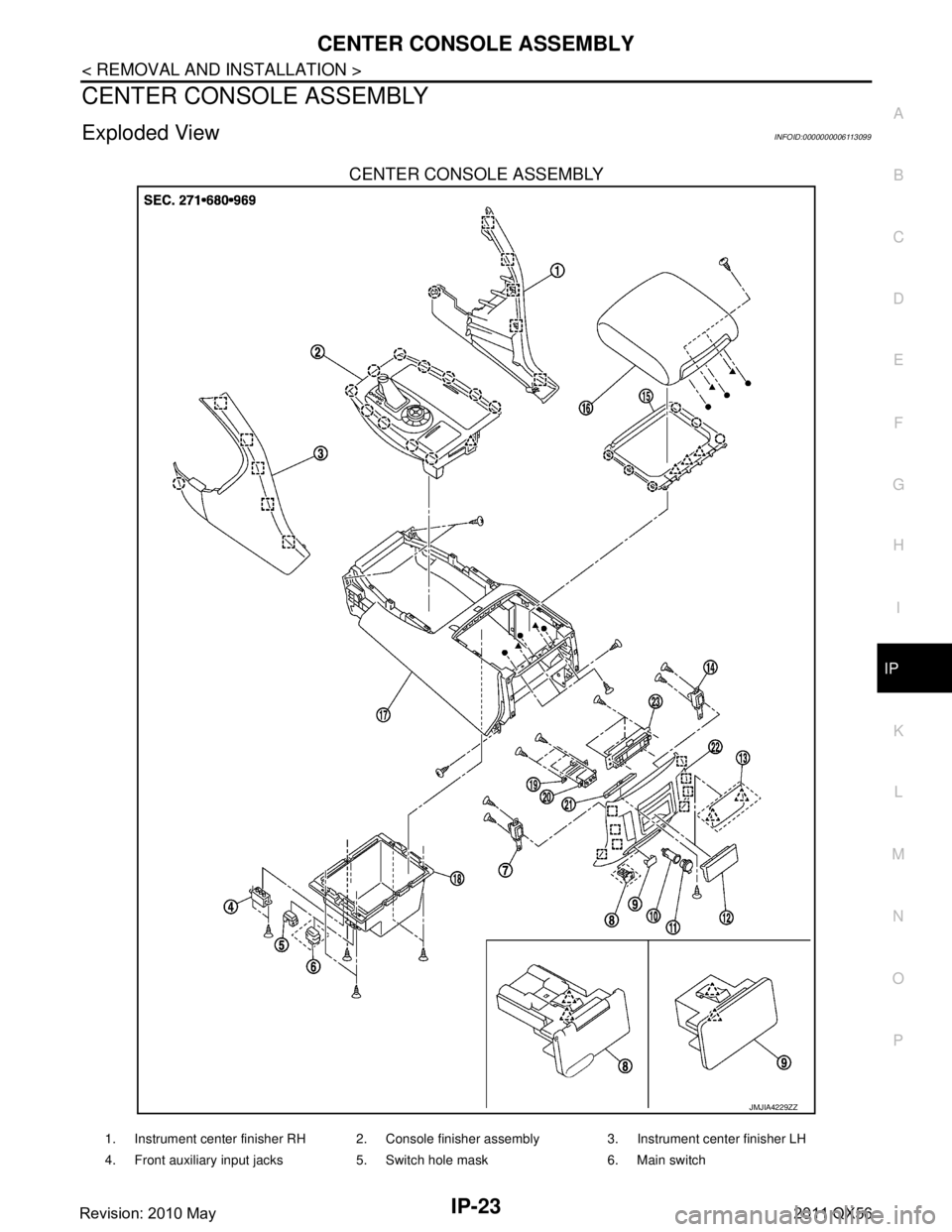
CENTER CONSOLE ASSEMBLY
Exploded ViewINFOID:0000000006113099
CENTER CONSOLE ASSEMBLY
JMJIA4229ZZ
1. Instrument center finisher RH 2. Console finisher assembly 3. Instrument center finisher LH
4. Front auxiliary input jacks 5. Switch hole mask 6. Main switch
Revision: 2010 May2011 QX56
Page 3414 of 5598

IP-24
< REMOVAL AND INSTALLATION >
CENTER CONSOLE ASSEMBLY
CONSOLE FINISHER ASSEMBLY
7. Second heated seat switch LH 8. 120W unit 9. Mask
10. Inner socket 11. Socket knob 12. Console ashtray
13. Mask (without ashtray) 14. Second heated seat switch RH 15. Console hinge cover
16. Console lid assembly 17. Console body assembly 18. Console box
19. Inside key antenna 20. Rear auxiliary input jacks 21. Console ashtray bracket
22. Console rear finisher 23. Rear A/C control: Clip
: Pawl
: Metal clip
JMJIA4230ZZ
1. AT control indicator assembly 2. 4WD: 4WD switch assembly 2WD: SNOW MODE/TOW MODE/
VDC OFF switch assembly3. Console pocket assembly
4. Cup holder assembly 5. Inner socket 6. Socket ring
7. Socket knob 8. USB connector 9. Inner case
10. Coin pocket : Clip
: Pawl
Revision: 2010 May2011 QX56
Page 3415 of 5598
CENTER CONSOLE ASSEMBLYIP-25
< REMOVAL AND INSTALLATION >
C
DE
F
G H
I
K L
M A
B
IP
N
O P
Removal and InstallationINFOID:0000000006113100
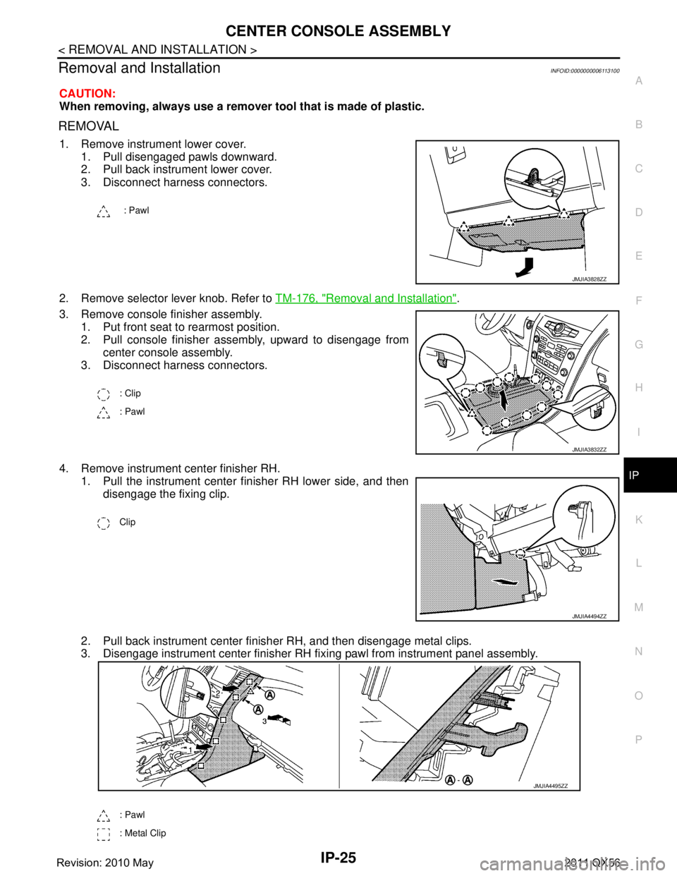
CAUTION:
When removing, always use a remover tool that is made of plastic.
REMOVAL
1. Remove instrument lower cover.
1. Pull disengaged pawls downward.
2. Pull back instrument lower cover.
3. Disconnect harness connectors.
2. Remove selector lever knob. Refer to TM-176, "
Removal and Installation".
3. Remove console finisher assembly. 1. Put front seat to rearmost position.
2. Pull console finisher assembly, upward to disengage from center console assembly.
3. Disconnect harness connectors.
4. Remove instrument center finisher RH. 1. Pull the instrument center finisher RH lower side, and then disengage the fixing clip.
2. Pull back instrument center finisher RH, and then disengage metal clips.
3. Disengage instrument center finisher RH fixi ng pawl from instrument panel assembly.
: Pawl
JMJIA3828ZZ
: Clip
: Pawl
JMJIA3832ZZ
Clip
JMJIA4494ZZ
: Pawl
: Metal Clip
JMJIA4495ZZ
Revision: 2010 May2011 QX56
Page 3416 of 5598
IP-26
< REMOVAL AND INSTALLATION >
CENTER CONSOLE ASSEMBLY
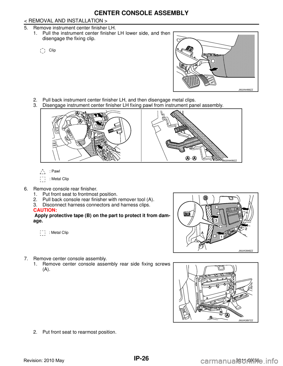
5. Remove instrument center finisher LH.1. Pull the instrument center finisher LH lower side, and thendisengage the fixing clip.
2. Pull back instrument center finisher LH, and then disengage metal clips.
3. Disengage instrument center finisher LH fi xing pawl from instrument panel assembly.
6. Remove console rear finisher. 1. Put front seat to frontmost position.
2. Pull back console rear finisher with remover tool (A).
3. Disconnect harness connectors and harness clips.
CAUTION:
Apply protective tape (B) on the part to protect it from dam-
age.
7. Remove center console assembly. 1. Remove center console assembly rear side fixing screws
(A).
2. Put front seat to rearmost position.
Clip
JMJIA4496ZZ
: Pawl
: Metal Clip
JMJIA4499ZZ
: Metal Clip
JMJIA3848ZZ
JMJIA3897ZZ
Revision: 2010 May2011 QX56
Page 3417 of 5598
CENTER CONSOLE ASSEMBLYIP-27
< REMOVAL AND INSTALLATION >
C
DE
F
G H
I
K L
M A
B
IP
N
O P
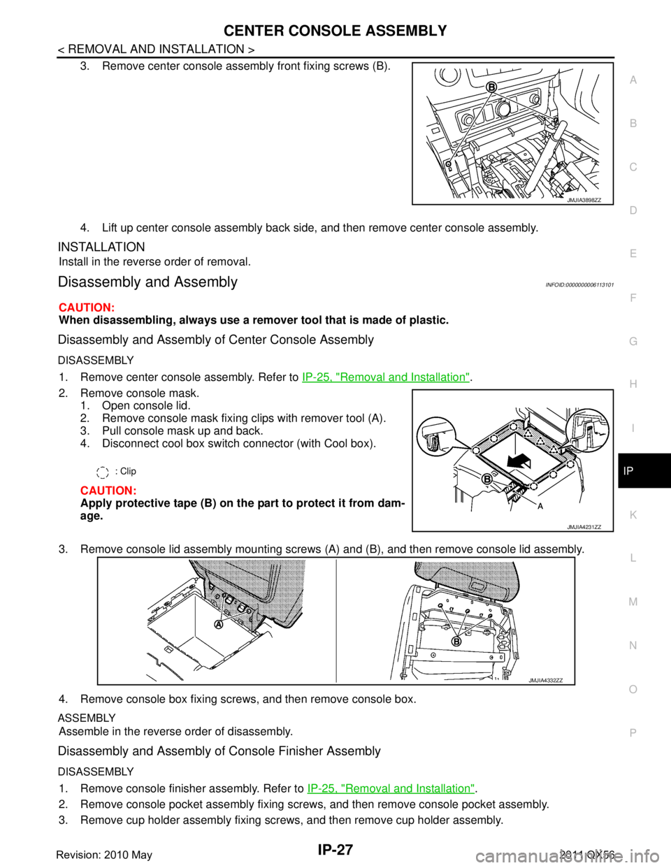
3. Remove center console assembly front fixing screws (B).
4. Lift up center console assembly back side, and then remove center console assembly.
INSTALLATION
Install in the reverse order of removal.
Disassembly and AssemblyINFOID:0000000006113101
CAUTION:
When disassembling, always use a remover tool that is made of plastic.
Disassembly and Assembly of Center Console Assembly
DISASSEMBLY
1. Remove center console assembly. Refer to IP-25, "Removal and Installation".
2. Remove console mask. 1. Open console lid.
2. Remove console mask fixing clips with remover tool (A).
3. Pull console mask up and back.
4. Disconnect cool box switch connector (with Cool box).
CAUTION:
Apply protective tape (B) on the part to protect it from dam-
age.
3. Remove console lid assembly mounting screws (A) and (B), and then remove console lid assembly.
4. Remove console box fixing screws, and then remove console box.
ASSEMBLY
Assemble in the reverse order of disassembly.
Disassembly and Assembly of Console Finisher Assembly
DISASSEMBLY
1. Remove console finisher assembly. Refer to IP-25, "Removal and Installation".
2. Remove console pocket assembly fixing screws, and then remove console pocket assembly.
3. Remove cup holder assembly fixing screws, and then remove cup holder assembly.
JMJIA3898ZZ
: Clip
JMJIA4231ZZ
JMJIA4332ZZ
Revision: 2010 May2011 QX56
Page 3418 of 5598

IP-28
< REMOVAL AND INSTALLATION >
CENTER CONSOLE ASSEMBLY
4. Remove console power socket. Refer to PWO-11, "CONSOLE POWER SOCKET (REAR) : Removal and
Installation".
5. Remove 4WD switch assembly (2WD: SNOW MODE/TOW MODE/VDC OFF switch assembly). Refer to DLN-108, "
Removal and Installation".
ASSEMBLY
Assemble in the reverse order of disassembly.
Revision: 2010 May2011 QX56
Page 3731 of 5598

MIR-26
< SYMPTOM DIAGNOSIS >
SQUEAK AND RATTLE TROUBLE DIAGNOSES
Insulates where slight movement is present. Ideal for instrument panel applications.
SILICONE GREASE
Used in place of UHMW tape that will be visible or not fit. Will only last a few months.
SILICONE SPRAY
Use when grease cannot be applied.
DUCT TAPE
Use to eliminate movement.
CONFIRM THE REPAIR
Confirm that the cause of a noise is repaired by test driving the vehicle. Operate the vehicle under the same
conditions as when the noise originally occurred. Refer to the notes on the Diagnostic Worksheet.
Inspection ProcedureINFOID:0000000006257248
Refer to Table of Contents for specific component removal and installationinformation.
INSTRUMENT PANEL
Most incidents are caused by contact and movement between:
1. The cluster lid A and instrument panel
2. Acrylic lens and combination meter housing
3. Instrument panel to front pillar garnish
4. Instrument panel to windshield
5. Instrument panel mounting pins
6. Wiring harnesses behind the combination meter
7. A/C defroster duct and duct joint
These incidents can usually be located by tapping or moving the components to duplicate the noise or by
pressing on the components while driving to stop the noise. Most of these incidents can be repaired by
applying felt cloth tape or silicon spray (in hard to reach areas). Urethane pads can be used to insulate
wiring harness.
CAUTION:
Do not use silicone spray to is olate a squeak or rattle. If you saturatethe area with silicone, you
will not be able to recheck the repair.
CENTER CONSOLE
Components to pay attention to include:
1. Shifter assembly cover to finisher
2. A/C control unit and cluster lid C
3. Wiring harnesses behind audio and A/C control unit
The instrument panel repair and isolation pr ocedures also apply to thecenter console.
DOORS
Pay attention to the:
1. Finisher and inner panel making a slapping noise
2. Inside handle escutcheon to door finisher
3. Wiring harnesses tapping
4. Door striker out of alignment causing a popping noise on startsand stops
Tapping or moving the components or pressing on them wh ile driving to duplicate the conditions can isolate
many of these incidents. You can usually insulate the areas with felt cloth tape or insulator foam blocks from
the Nissan Squeak and Rattle Kit (J-43980) to repair the noise.
TRUNK
Trunk noises are often caused by a loose jack or loose items put intothe trunk by the owner.
In addition look for:
1. Trunk lid dumpers out of adjustment
2. Trunk lid striker out of adjustment
3. The trunk lid torsion bars knocking together
4. A loose license plate or bracket
Revision: 2010 May2011 QX56
Page 3836 of 5598
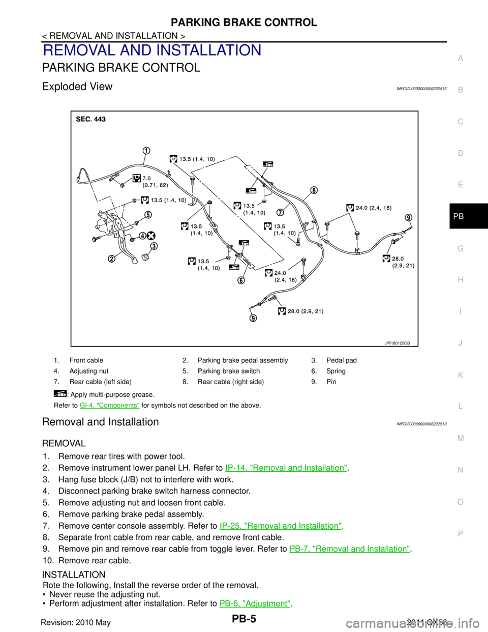
PARKING BRAKE CONTROLPB-5
< REMOVAL AND INSTALLATION >
C
DE
G H
I
J
K L
M A
B
PB
N
O P
REMOVAL AND INSTALLATION
PARKING BRAKE CONTROL
Exploded ViewINFOID:0000000006222512
Removal and InstallationINFOID:0000000006222513
REMOVAL
1. Remove rear tires with power tool.
2. Remove instrument lower panel LH. Refer to IP-14, "
Removal and Installation".
3. Hang fuse block (J/B) not to interfere with work.
4. Disconnect parking brake switch harness connector.
5. Remove adjusting nut and loosen front cable.
6. Remove parking brake pedal assembly.
7. Remove center console assembly. Refer to IP-25, "
Removal and Installation".
8. Separate front cable from rear cable, and remove front cable.
9. Remove pin and remove rear cable from toggle lever. Refer to PB-7, "
Removal and Installation".
10. Remove rear cable.
INSTALLATION
Rote the following, Install the reverse order of the removal.
Never reuse the adjusting nut.
Perform adjustment after installation. Refer to PB-6, "
Adjustment".
1. Front cable 2. Parking brake pedal assembly 3. Pedal pad
4. Adjusting nut 5. Parking brake switch 6. Spring
7. Rear cable (left side) 8. Rear cable (right side) 9. Pin
: Apply multi-purpose grease.
Refer to GI-4, "
Components" for symbols not described on the above.
JPFIB0125GB
Revision: 2010 May2011 QX56
Page 4173 of 5598
![INFINITI QX56 2011 Factory Owners Guide
PWO-14
< SYSTEM DESCRIPTION >[AC 120 V OUTLET]
COMPONENT PARTS
SYSTEM DESCRIPTION
COMPONENT PARTS
Component Parts LocationINFOID:0000000006257066
Component DescriptionINFOID:0000000006257067
Inverter INFINITI QX56 2011 Factory Owners Guide
PWO-14
< SYSTEM DESCRIPTION >[AC 120 V OUTLET]
COMPONENT PARTS
SYSTEM DESCRIPTION
COMPONENT PARTS
Component Parts LocationINFOID:0000000006257066
Component DescriptionINFOID:0000000006257067
Inverter](/img/42/57033/w960_57033-4172.png)
PWO-14
< SYSTEM DESCRIPTION >[AC 120 V OUTLET]
COMPONENT PARTS
SYSTEM DESCRIPTION
COMPONENT PARTS
Component Parts LocationINFOID:0000000006257066
Component DescriptionINFOID:0000000006257067
Inverter UnitINFOID:0000000006257068
The inverter unit converts an applied power supply
voltage (approximately DC 12 V) to AC 120 V and outputs
the converted voltage.
AC120 V Outlet Main SwitchINFOID:0000000006257069
The operation of the switch enables the inverter unit to activate/inactivate and turn ON/OFF AC 120 V output.
AC120 V OutletINFOID:0000000006257070
The AC 120 V outlet allows using AC 120 V converted in the inverter unit as an outlet.
1. AC 120 V outlet main switch 2. Inverter unit 3. AC 120 V outlet
A. Inside of console box B. Center console remove condition
JSMIA0371ZZ
Component Reference
Inverter unit PWO-14, "
Inverter Unit"
AC 120 V outlet main switchPWO-14, "AC120 V Outlet Main Switch"
AC 120 V outletPWO-14, "AC120 V Outlet"
Revision: 2010 May2011 QX56
Page 4194 of 5598
![INFINITI QX56 2011 Factory Owners Guide
PWO
AC 120V OUTLET MAIN SWPWO-35
< REMOVAL AND INSTALLATION > [AC 120 V OUTLET]
C
D
E
F
G H
I
J
K L
B A
O P
N
AC 120V OUTLET MAIN SW
Removal and InstallationINFOID:0000000006257132
REMOVAL
1. Remove INFINITI QX56 2011 Factory Owners Guide
PWO
AC 120V OUTLET MAIN SWPWO-35
< REMOVAL AND INSTALLATION > [AC 120 V OUTLET]
C
D
E
F
G H
I
J
K L
B A
O P
N
AC 120V OUTLET MAIN SW
Removal and InstallationINFOID:0000000006257132
REMOVAL
1. Remove](/img/42/57033/w960_57033-4193.png)
PWO
AC 120V OUTLET MAIN SWPWO-35
< REMOVAL AND INSTALLATION > [AC 120 V OUTLET]
C
D
E
F
G H
I
J
K L
B A
O P
N
AC 120V OUTLET MAIN SW
Removal and InstallationINFOID:0000000006257132
REMOVAL
1. Remove console body assembly. Refer to
IP-23, "Exploded View".
2. Disengage pawl. Then remove AC 120 V outlet main switch from center console assembly.
INSTALLATION
Install in the reverse order of removal.
Revision: 2010 May2011 QX56