INFINITI QX56 2011 Factory Service Manual
Manufacturer: INFINITI, Model Year: 2011, Model line: QX56, Model: INFINITI QX56 2011Pages: 5598, PDF Size: 94.53 MB
Page 941 of 5598

CHG-28
< REMOVAL AND INSTALLATION >
ALTERNATOR
Inspection
INFOID:0000000006274885
ALTERNATOR PULLEY INSPECTION
Perform the following.
Make sure that alternator pulley does not rattle.
Make sure that alternator pulley nut is tight. Refer to CHG-25, "
Exploded View".
Revision: 2010 May2011 QX56
Page 942 of 5598

CHG
SERVICE DATA AND SPECIFICATIONS (SDS)
CHG-29
< SERVICE DATA AND SPECIFICATIONS (SDS)
C
D E
F
G H
I
J
K L
B A
O P
N
SERVICE DATA AND SPECIFICATIONS (SDS)
SERVICE DATA AND SPECIFICATIONS (SDS)
AlternatorINFOID:0000000006274881
*: Adjustment range of power generation voltage variable control is 11.4 - 15.6 V. Ty p e
A002TX1491
MITSUBISHI make
Nominal rating [V - A] 12 -150
Ground polarity Negative
Minimum revolution under no-load (When 13.5 V is ap-
plied) [rpm] Less than 1,300
Hot output current (When 13.5 V is applied) [A/rpm] More than 57/1,500
More than 126/2,500
More than 152/5,000
Regulated output voltage [V] 14.1 - 14.7
*
Revision: 2010 May2011 QX56
Page 943 of 5598

CO-1
ENGINE
C
DE
F
G H
I
J
K L
M
SECTION CO
A
CO
N
O P
CONTENTS
ENGINE COOLING SYSTEM
PRECAUTION ................ ...............................2
PRECAUTIONS .............................................. .....2
Precaution for Supplemental Restraint System
(SRS) "AIR BAG" and "SEAT BELT PRE-TEN-
SIONER" ............................................................. ......
2
PREPARATION ............................................3
PREPARATION .............................................. .....3
Commercial Service Tools ................................. ......3
SYSTEM DESCRIPTION ..............................4
DESCRIPTION ............................................... .....4
Engine Cooling System ..................................... ......4
Engine Cooling System Schematic .........................5
SYMPTOM DIAGNOSIS ...............................6
OVERHEATING CAUSE ANALYSIS ............. .....6
Troubleshooting Chart ........................................ ......6
PERIODIC MAINTENANCE ..........................8
ENGINE COOLANT ....................................... .....8
Inspection ............................................................ ......8
Draining .....................................................................8
Refilling .....................................................................9
Flushing ...................................................................10
RADIATOR .........................................................11
RESERVOIR TANK CAP ..........................................11
RESERVOIR TANK CAP : Inspection ................. ....11
RADIATOR ............................................................. ....11
RADIATOR : Inspection ...........................................11
REMOVAL AND INSTALLATION ...............13
RADIATOR ....................................... .................13
Exploded View ..................................................... ....13
Removal and Installation .........................................13
Inspection ................................................................15
COOLING FAN ..................................................16
Exploded View .........................................................16
Removal and Installation .........................................16
Inspection ................................................................17
WATER PUMP ..................................................18
Exploded View .........................................................18
Removal and Installation .........................................18
Inspection ................................................................19
WATER INLET AND THERMOSTAT ASSEM-
BLY ....................................................................
20
Exploded View .........................................................20
Removal and Installation .........................................20
Inspection ................................................................21
SERVICE DATA AND SPECIFICATIONS
(SDS) ............... .............................................
23
SERVICE DATA AND SPECIFICATIONS
(SDS) .................................................................
23
Periodical Maintenance Specification ................ ....23
Radiator ...................................................................23
Thermostat ..............................................................23
Revision: 2010 May2011 QX56
Page 944 of 5598

CO-2
< PRECAUTION >
PRECAUTIONS
PRECAUTION
PRECAUTIONS
Precaution for Supplemental Restraint System (SRS) "AIR BAG" and "SEAT BELT
PRE-TENSIONER"
INFOID:0000000006417198
The Supplemental Restraint System such as “A IR BAG” and “SEAT BELT PRE-TENSIONER”, used along
with a front seat belt, helps to reduce the risk or severi ty of injury to the driver and front passenger for certain
types of collision. This system includes seat belt switch inputs and dual stage front air bag modules. The SRS
system uses the seat belt switches to determine the front air bag deployment, and may only deploy one front
air bag, depending on the severity of a collision and w hether the front occupants are belted or unbelted.
Information necessary to service the system safely is included in the “SRS AIR BAG” and “SEAT BELT” of this
Service Manual.
WARNING:
• To avoid rendering the SRS inopera tive, which could increase the risk of personal injury or death in
the event of a collision that would result in air bag inflation, all maintenance must be performed by
an authorized NISS AN/INFINITI dealer.
Improper maintenance, including in correct removal and installation of the SRS, can lead to personal
injury caused by unintent ional activation of the system. For re moval of Spiral Cable and Air Bag
Module, see the “SRS AIR BAG”.
Do not use electrical test equipmen t on any circuit related to the SRS unless instructed to in this
Service Manual. SRS wiring harnesses can be identi fied by yellow and/or orange harnesses or har-
ness connectors.
PRECAUTIONS WHEN USING POWER TOOLS (AIR OR ELECTRIC) AND HAMMERS
WARNING:
When working near the Air Bag Diagnosis Sensor Unit or other Air Bag System sensors with the ignition ON or engine running, DO NOT use air or electric power tools or strike near the sensor(s)
with a hammer. Heavy vibration could activate the sensor(s) and deploy the air bag(s), possibly
causing serious injury.
When using air or electric power tools or hammers , always switch the ignition OFF, disconnect the
battery, and wait at least 3 minu tes before performing any service.
Revision: 2010 May2011 QX56
Page 945 of 5598

PREPARATIONCO-3
< PREPARATION >
C
DE
F
G H
I
J
K L
M A
CO
NP
O
PREPARATION
PREPARATION
Commercial Service ToolsINFOID:0000000006289653
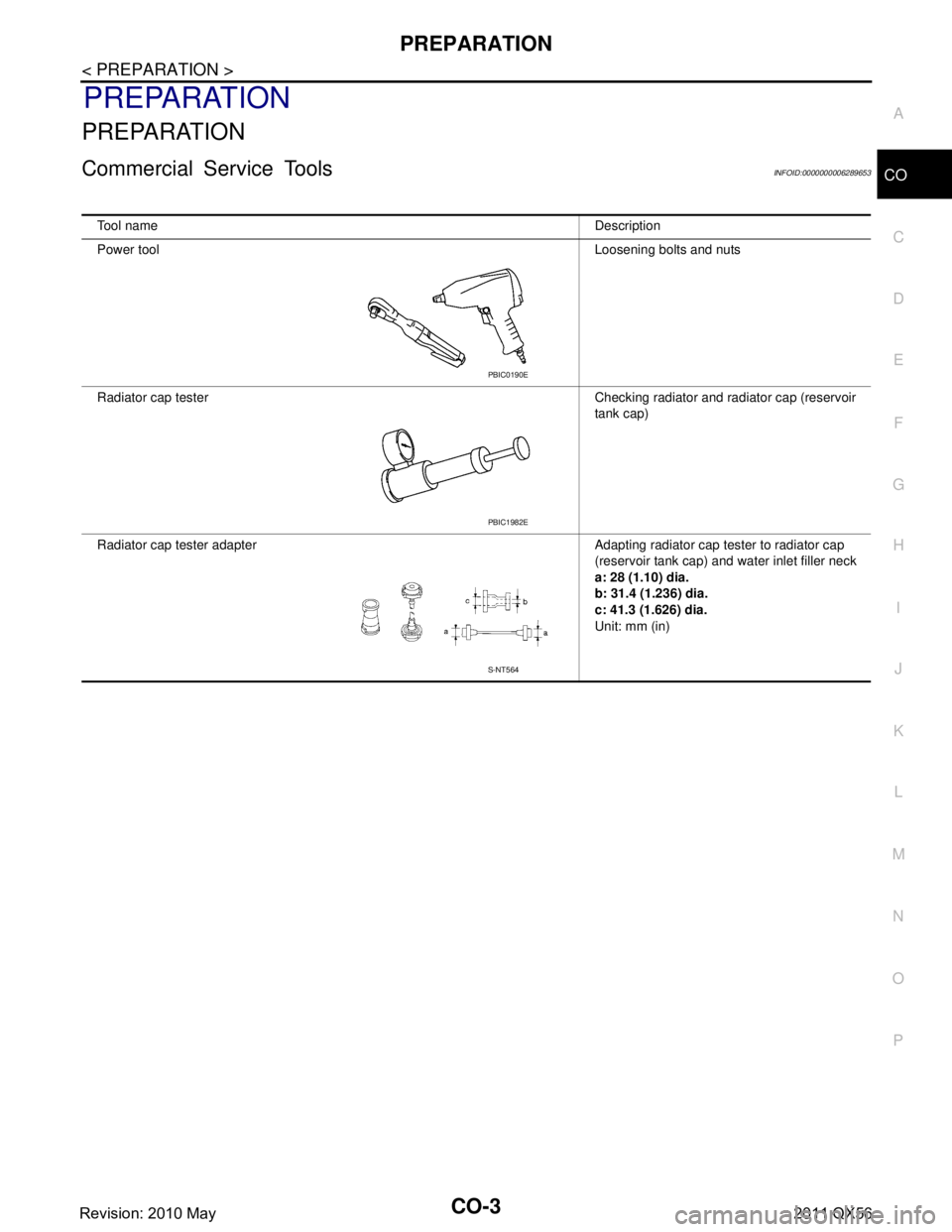
Tool name
Description
Power tool Loosening bolts and nuts
Radiator cap tester Checking radiator and radiator cap (reservoir tank cap)
Radiator cap tester adapter Adapting radiator cap tester to radiator cap (reservoir tank cap) and water inlet filler neck
a: 28 (1.10) dia.
b: 31.4 (1.236) dia.
c: 41.3 (1.626) dia.
Unit: mm (in)
PBIC0190E
PBIC1982E
S-NT564
Revision: 2010 May2011 QX56
Page 946 of 5598

CO-4
< SYSTEM DESCRIPTION >
DESCRIPTION
SYSTEM DESCRIPTION
DESCRIPTION
Engine Cooling SystemINFOID:0000000006289654
JPBIA4247GB
Revision: 2010 May2011 QX56
Page 947 of 5598

DESCRIPTIONCO-5
< SYSTEM DESCRIPTION >
C
DE
F
G H
I
J
K L
M A
CO
NP
O
Engine Cooling System SchematicINFOID:0000000006289655
JPBIA4248GB
Revision: 2010 May2011 QX56
Page 948 of 5598

CO-6
< SYMPTOM DIAGNOSIS >
OVERHEATING CAUSE ANALYSIS
SYMPTOM DIAGNOSIS
OVERHEATING CAUSE ANALYSIS
Troubleshooting ChartINFOID:0000000006289656
Symptom Check items
Cooling sys-
tem parts
malfunction Poor heat transfer
Water pump malfunction Worn or loose drive belt
—
Thermostat stuck closed —
Damaged fins
Dust contamination or pa-
per clogging
Physical damage
Clogged radiator cooling
tube Excess foreign material
(rust, dirt, sand, etc.)
Reduced air flow Cooling fan does not oper-
ate
Fan assembly —
High resistance to fan rota-
tion
Damaged fan blades
Damaged radiator shroud — — —
Improper engine coolant
mixture ratio ———
Poor engine coolant quality — Engine coolant density —
Insufficient engine coolant Engine coolant leakageCooling hose
Loose clamp
Cracked hose
Water pump Poor sealing
Radiator cap Loose
Poor sealing
Radiator O-ring for da
mage, deterio-
ration or improper fitting
Cracked radiator tank
Cracked radiator core
Reservoir tank Cracked reservoir tank
Overflowing reservoir tank Exhaust gas leakage into
cooling system Cylinder head deterioration
Cylinder head gasket deteri-
oration
Revision: 2010 May2011 QX56
Page 949 of 5598

OVERHEATING CAUSE ANALYSISCO-7
< SYMPTOM DIAGNOSIS >
C
DE
F
G H
I
J
K L
M A
CO
NP
O
Except cool-
ing system
parts mal-
function — Overload on engine
Abusive driving
High engine rpm under no
load
Driving in low gear for ex-
tended time
Driving at extremely high
speed
Powertrain system malfunc-
tion
—
Installed improper size
wheels and tires
Dragging brakes
Improper ignition timing
Blocked or restricted air
flow Blocked bumper —
—
Blocked radiator grille
Installed car brassiere
Mud contamination or paper
clogging
Blocked radiator —
Blocked condenser Blocked air flow
Installed large fog lamp
Symptom Check items
Revision: 2010 May2011 QX56
Page 950 of 5598

CO-8
< PERIODIC MAINTENANCE >
ENGINE COOLANT
PERIODIC MAINTENANCE
ENGINE COOLANT
InspectionINFOID:0000000006289657
LEVEL
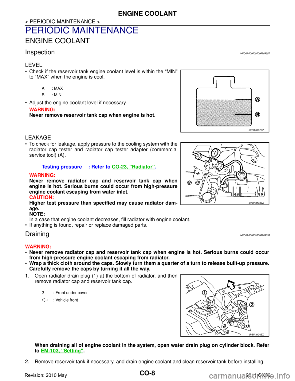
Check if the reservoir tank engine coolant level is within the “MIN”to “MAX” when the engine is cool.
Adjust the engine coolant level if necessary. WARNING:
Never remove reservoir tank cap when engine is hot.
LEAKAGE
To check for leakage, apply pressure to the cooling system with theradiator cap tester and radiator cap tester adapter (commercial
service tool) (A).
WARNING:
Never remove radiator cap and reservoir tank cap when
engine is hot. Serious burns could occur from high-pressure
engine coolant escaping from water inlet.
CAUTION:
Higher test pressure than specified may cause radiator dam-
age.
NOTE:
In a case that engine coolant decreas es, fill radiator with engine coolant.
If anything is found, repair or replace damaged parts.
DrainingINFOID:0000000006289658
WARNING:
Never remove radiator cap and reservoir tank cap when engine is hot. Serious burns could occur
from high-pressure engine co olant escaping from radiator.
Wrap a thick cloth around the caps. Slowly turn them a quarter of a turn to release built-up pressure.
Carefully remove the caps by turning it all the way.
1. Open radiator drain plug (1) at the bottom of radiator, and then remove radiator cap and reservoir tank cap.
When draining all of engine cool ant in the system, open water drai n plug on cylinder block. Refer
to EM-103, "
Setting".
2. Remove reservoir tank if necessary, and drain engine coolant and clean reservoir tank before installing.
A: MAX
B: MIN
JPBIA0102ZZ
Testing pressure : Refer to CO-23, "Radiator".
JPBIA3432ZZ
2 : Front under cover
: Vehicle front
JPBIA3430ZZ
Revision: 2010 May2011 QX56