ISUZU KB P190 2007 Workshop Repair Manual
Manufacturer: ISUZU, Model Year: 2007, Model line: KB P190, Model: ISUZU KB P190 2007Pages: 6020, PDF Size: 70.23 MB
Page 1331 of 6020
Engine Control System (4JH1) 6E-297
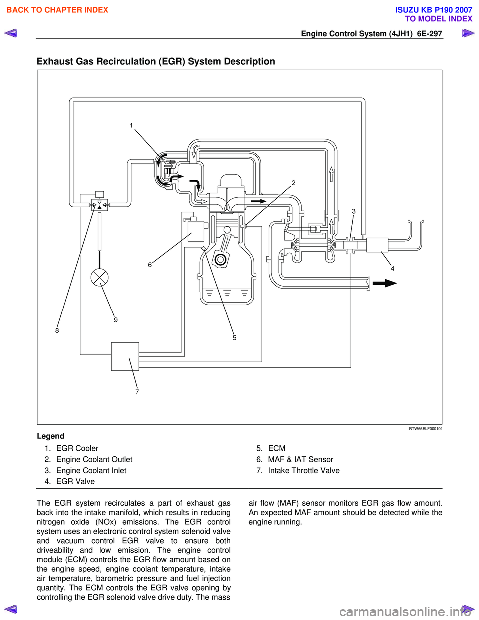
Exhaust Gas Recirculation (EGR) System Description
RTW 66ELF000101
Legend
1. EGR Cooler
2. Engine Coolant Outlet
3. Engine Coolant Inlet
4. EGR Valve
5. ECM
6. MAF & IAT Sensor
7. Intake Throttle Valve
The EGR system recirculates a part of exhaust gas
back into the intake manifold, which results in reducing
nitrogen oxide (NOx) emissions. The EGR control
system uses an electronic control system solenoid valve
and vacuum control EGR valve to ensure both
driveability and low emission. The engine control
module (ECM) controls the EGR flow amount based on
the engine speed, engine coolant temperature, intake
air temperature, barometric pressure and fuel injection
quantity. The ECM controls the EGR valve opening b
y
controlling the EGR solenoid valve drive duty. The mass
air flow (MAF) sensor monitors EGR gas flow amount.
An expected MAF amount should be detected while the
engine running.
BACK TO CHAPTER INDEX
TO MODEL INDEX
ISUZU KB P190 2007
Page 1332 of 6020
6E-298 Engine Control System (4JH1)
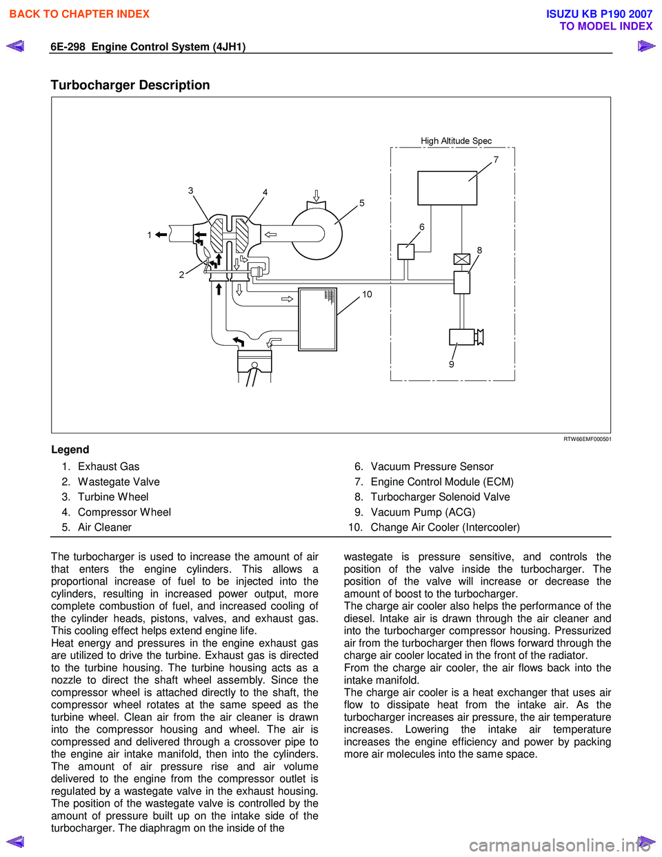
Turbocharger Description
RTW 66EMF000501
Legend
1. Exhaust Gas
2. W astegate Valve
3. Turbine W heel
4. Compressor W heel
5. Air Cleaner
6. Vacuum Pressure Sensor
7. Engine Control Module (ECM)
8. Turbocharger Solenoid Valve
9. Vacuum Pump (ACG)
10. Change Air Cooler (Intercooler)
The turbocharger is used to increase the amount of ai
r
that enters the engine cylinders. This allows a
proportional increase of fuel to be injected into the
cylinders, resulting in increased power output, more
complete combustion of fuel, and increased cooling o
f
the cylinder heads, pistons, valves, and exhaust gas.
This cooling effect helps extend engine life.
Heat energy and pressures in the engine exhaust gas
are utilized to drive the turbine. Exhaust gas is directed
to the turbine housing. The turbine housing acts as a
nozzle to direct the shaft wheel assembly. Since the
compressor wheel is attached directly to the shaft, the
compressor wheel rotates at the same speed as the
turbine wheel. Clean air from the air cleaner is drawn
into the compressor housing and wheel. The air is
compressed and delivered through a crossover pipe to
the engine air intake manifold, then into the cylinders.
The amount of air pressure rise and air volume
delivered to the engine from the compressor outlet is
regulated by a wastegate valve in the exhaust housing.
The position of the wastegate valve is controlled by the
amount of pressure built up on the intake side of the
turbocharger. The diaphragm on the inside of the
wastegate is pressure sensitive, and controls the
position of the valve inside the turbocharger. The
position of the valve will increase or decrease the
amount of boost to the turbocharger.
The charge air cooler also helps the performance of the
diesel. Intake air is drawn through the air cleaner and
into the turbocharger compressor housing. Pressurized
air from the turbocharger then flows forward through the
charge air cooler located in the front of the radiator.
From the charge air cooler, the air flows back into the
intake manifold.
The charge air cooler is a heat exchanger that uses ai
r
flow to dissipate heat from the intake air. As the
turbocharger increases air pressure, the air temperature
increases. Lowering the intake air temperature
increases the engine efficiency and power by packing
more air molecules into the same space.
BACK TO CHAPTER INDEX
TO MODEL INDEX
ISUZU KB P190 2007
Page 1333 of 6020
Engine Control System (4JH1) 6E-299
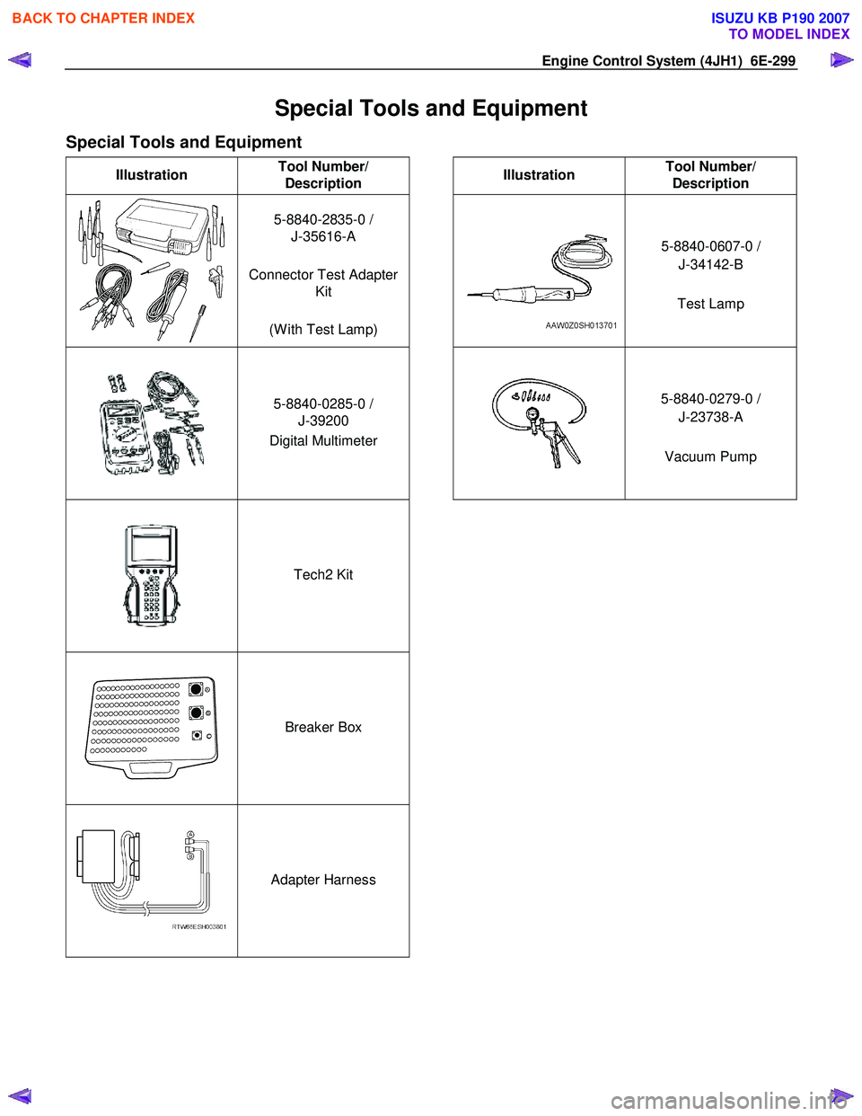
Special Tools and Equipment
Special Tools and Equipment
Illustration Tool Number/
Description
Illustration Tool Number/
Description
5-8840-2835-0 /
J-35616-A
Connector Test Adapter Kit
(W ith Test Lamp)
5-8840-0607-0 /
J-34142-B
Test Lamp
5-8840-0285-0 /
J-39200
Digital Multimeter
5-8840-0279-0 /
J-23738-A
Vacuum Pump
Tech2 Kit
Breaker Box
Adapter Harness
BACK TO CHAPTER INDEX
TO MODEL INDEX
ISUZU KB P190 2007
Page 1334 of 6020
SECTION 6F
EXHAUST SYSTEM
TABLE OF CONTENTS
PAGE
Main Data and Specifications ........................................................................................... 6F - 2
General Description .......................................................................................................... 6 F - 3
Removal and Installation .................................................................................................. 6F - 4
Inspection and Repair ....................................................................................................... 6F - 6
General Description .......................................................................................................... 6 F -7
EGR System Diagram........................................................................................................ 6F 9
Inspection ..................................................................................................................... ..... 6F-11
EGR Cooler (4JA1TC/4JH1TC Euro-III model)................................................................. 6F-12
Turbocharger ................................................................................................................... .. 6F -15
Main Data and Specifications....................................................................................... 6F -15
General Description .......................................................................................................... 6 F -16
Inspection and Repair ....................................................................................................... 6F -17
Special Tools .................................................................................................................. ... 6F -19
IHI Service Network ........................................................................................................... 6F -20
EXH
AU ST SY STEM 6F – 1
BACK TO CHAPTER INDEX
TO MODEL INDEX
ISUZU KB P190 2007
Page 1335 of 6020
6F – 2 EXHAUST SYSTEM
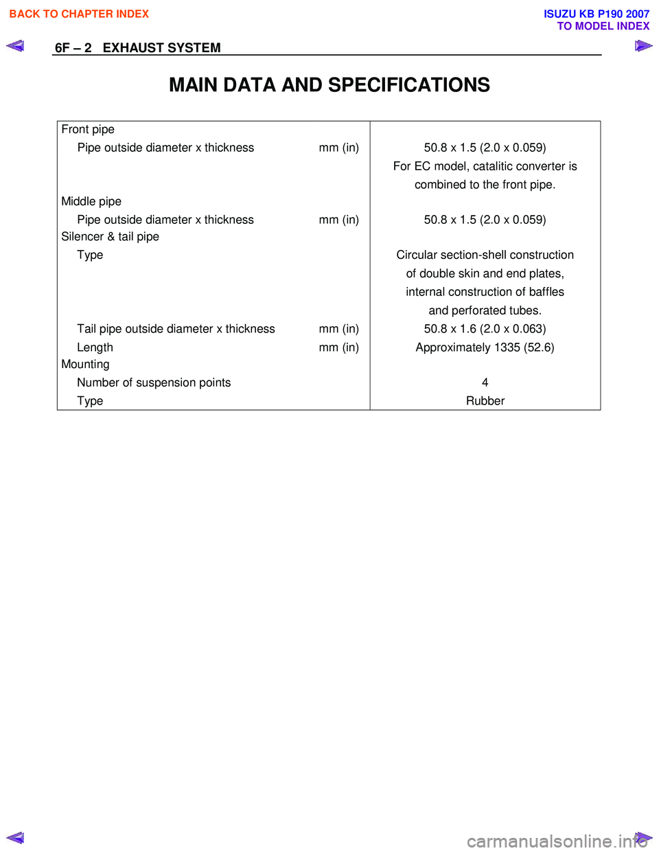
MAIN DATA AND SPECIFICATIONS
Front pipe
Pipe outside diameter x thickness mm (in) 50.8 x 1.5 (2.0 x 0.059)
For EC model, catalitic converter is
combined to the front pipe.
Middle pipe
Pipe outside diameter x thickness mm (in) 50.8 x 1.5 (2.0 x 0.059)
Silencer & tail pipe
Type Circular section-shell construction
of double skin and end plates,
internal construction of baffles
and perforated tubes.
Tail pipe outside diameter x thickness mm (in) 50.8 x 1.6 (2.0 x 0.063)
Length mm (in) Approximately 1335 (52.6)
Mounting
Number of suspension points 4
Type Rubber
BACK TO CHAPTER INDEX
TO MODEL INDEX
ISUZU KB P190 2007
Page 1336 of 6020
EXHAUST SYSTEM 6F – 3
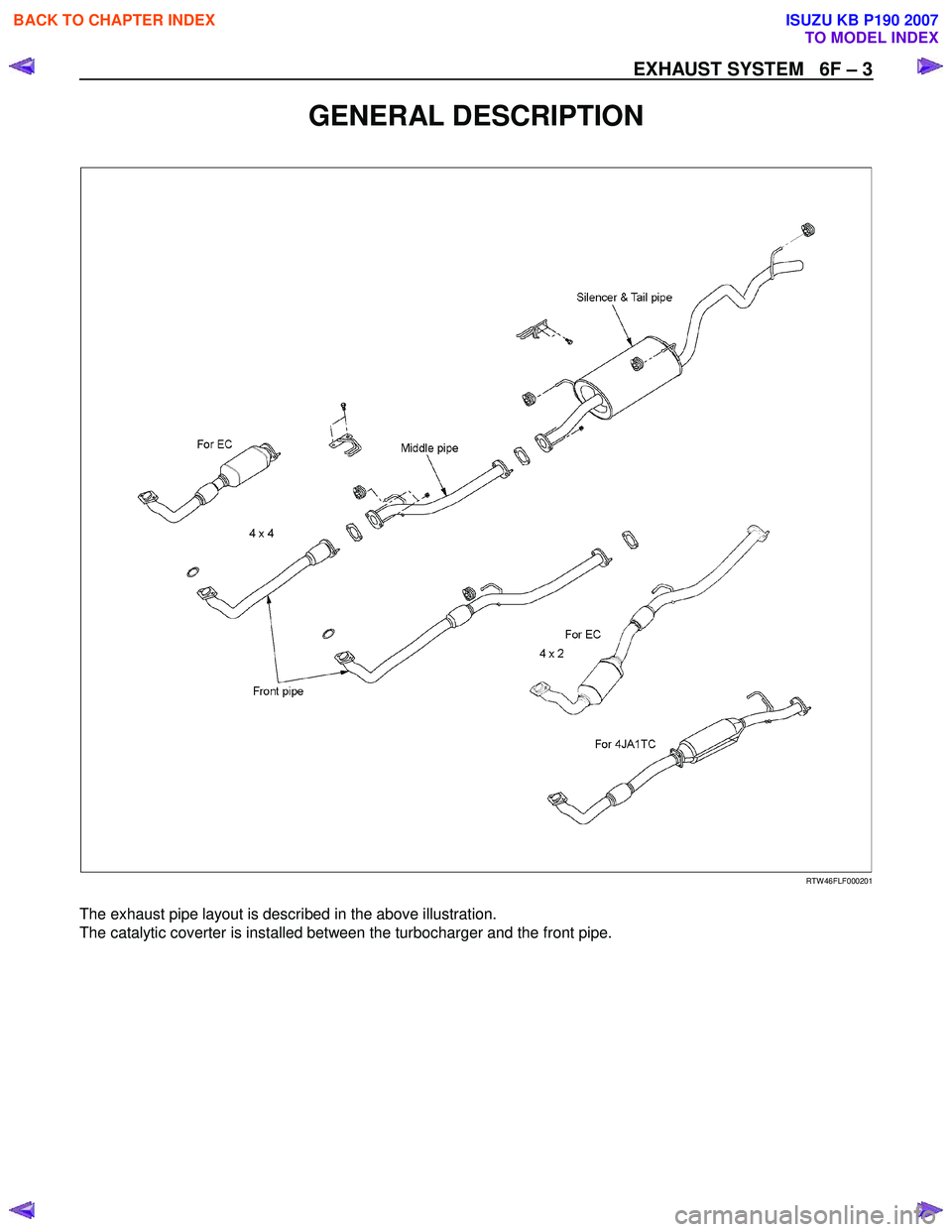
GENERAL DESCRIPTION
RTW 46FLF000201
The exhaust pipe layout is described in the above illustration.
The catalytic coverter is installed between the turbocharger and the front pipe.
BACK TO CHAPTER INDEX
TO MODEL INDEX
ISUZU KB P190 2007
Page 1337 of 6020
6F – 4 EXHAUST SYSTEM
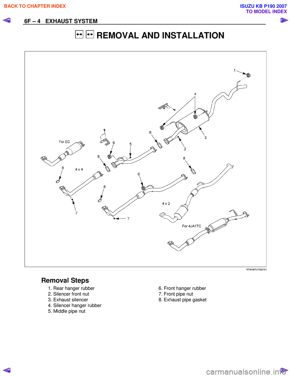
REMOVAL AND INSTALLATION
RTW 46FLF000101
Removal Steps
1. Rear hanger rubber
2. Silencer front nut
3. Exhaust silencer
4. Silencer hanger rubber
5. Middle pipe nut
6. Front hanger rubber
7. Front pipe nut
8. Exhaust pipe gasket
BACK TO CHAPTER INDEX
TO MODEL INDEX
ISUZU KB P190 2007
Page 1338 of 6020
EXHAUST SYSTEM 6F – 5
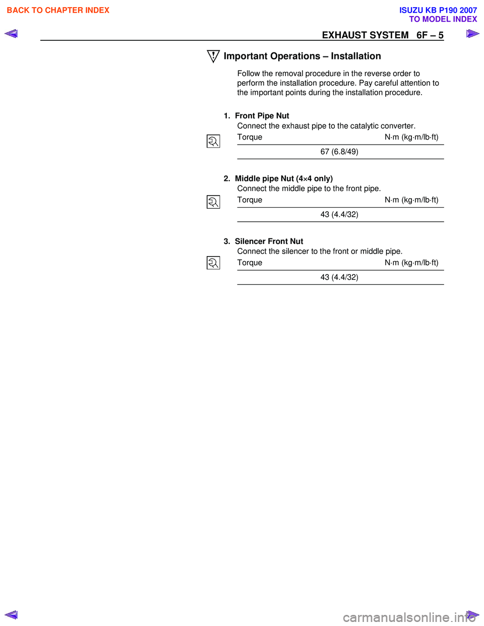
Important Operations – Installation
Follow the removal procedure in the reverse order to
perform the installation procedure. Pay careful attention to
the important points during the installation procedure.
1. Front Pipe Nut Connect the exhaust pipe to the catalytic converter.
Torque N ⋅m (kg ⋅m/lb ⋅ft)
67 (6.8/49)
2. Middle pipe Nut (4 ×
××
×
4 only)
Connect the middle pipe to the front pipe.
Torque N ⋅m (kg ⋅m/lb ⋅ft)
43 (4.4/32)
3. Silencer Front Nut Connect the silencer to the front or middle pipe.
Torque N ⋅m (kg ⋅m/lb ⋅ft)
43 (4.4/32)
BACK TO CHAPTER INDEX
TO MODEL INDEX
ISUZU KB P190 2007
Page 1339 of 6020
6F – 6 EXHAUST SYSTEM
INSPECTION AND REPAIR
Make the necessary adjustments, repairs, and part replacements if excessive wear or damage is discovered during
inspection.
Front Exhaust Pipe
Exhaust Silencer
Check the pipes for corrosion, cracking, damage or
misalignment and repair as required.
Check the rubber rings for deterioration or damage and repair
as required.
Catalytic Converter
1. Inspect outside the catalytic converter for any hitting mark.
2. Visual check inside the catalytic converter for crack or break converter element.
3. If find any problem during the inspection, replace the catalytic converter assembly.
BACK TO CHAPTER INDEX
TO MODEL INDEX
ISUZU KB P190 2007
Page 1340 of 6020
EXHAUST SYSTEM 6F – 7
GENERAL DESCRIPTION
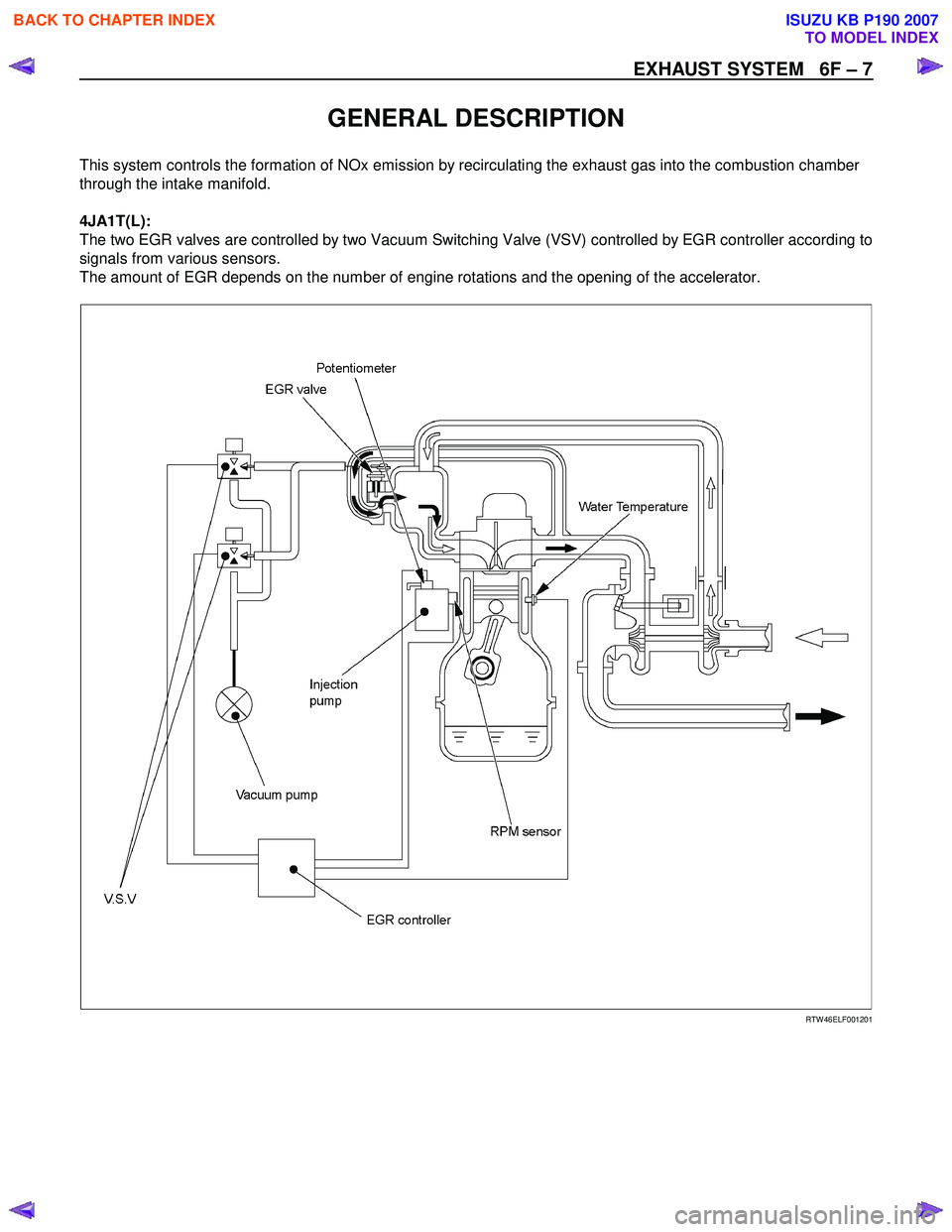
This system controls the formation of NOx emission by recirculating the exhaust gas into the combustion chamber
through the intake manifold.
4JA1T(L):
The two EGR valves are controlled by two Vacuum Switching Valve (VSV) controlled by EGR controller according to
signals from various sensors.
The amount of EGR depends on the number of engine rotations and the opening of the accelerator.
RTW 46ELF001201
BACK TO CHAPTER INDEX
TO MODEL INDEX
ISUZU KB P190 2007