relay ISUZU KB P190 2007 Workshop Repair Manual
[x] Cancel search | Manufacturer: ISUZU, Model Year: 2007, Model line: KB P190, Model: ISUZU KB P190 2007Pages: 6020, PDF Size: 70.23 MB
Page 3214 of 6020
Fuel System – V6 Page 6C – 12
A small amount of fuel may be released when
pressing on the Schrader valve. Cover the
fitting with a shop towel to absorb any fuel
spillage before removing the Schrader valve
sealing cap. Place the soiled towel in an
approved container for disposal.
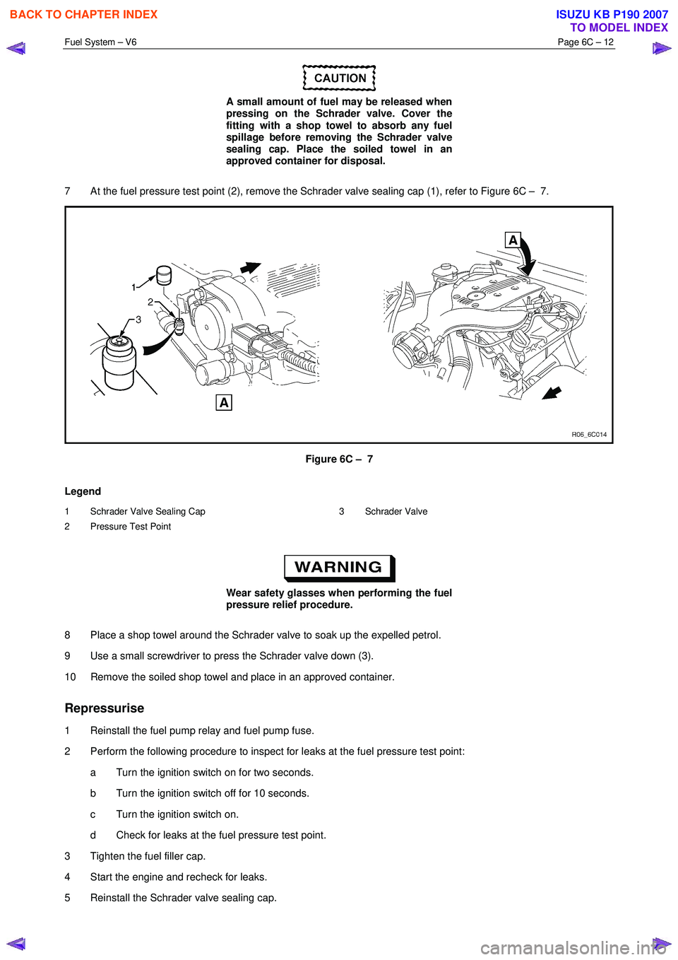
7 At the fuel pressure test point (2), remove the Schrader valve sealing cap (1), refer to Figure 6C – 7.
Figure 6C – 7
Legend
1 Schrader Valve Sealing Cap
2 Pressure Test Point 3 Schrader Valve
Wear safety glasses when performing the fuel
pressure relief procedure.
8 Place a shop towel around the Schrader valve to soak up the expelled petrol.
9 Use a small screwdriver to press the Schrader valve down (3).
10 Remove the soiled shop towel and place in an approved container.
Repressurise
1 Reinstall the fuel pump relay and fuel pump fuse.
2 Perform the following procedure to inspect for leaks at the fuel pressure test point: a Turn the ignition switch on for two seconds.
b Turn the ignition switch off for 10 seconds.
c Turn the ignition switch on.
d Check for leaks at the fuel pressure test point.
3 Tighten the fuel filler cap.
4 Start the engine and recheck for leaks.
5 Reinstall the Schrader valve sealing cap.
BACK TO CHAPTER INDEX
TO MODEL INDEX
ISUZU KB P190 2007
Page 3221 of 6020
Fuel System – V6 Page 6C – 19
Remove
• A depressurised fuel system contains fuel
in the fuel filter and fuel lines that can be
spilled during service operations.
• Fuel vapour remains in the fuel tank even
when completely empty. Seal all openings
in the fuel tank using suitable material or a
plastic plug. Ensure no naked flames or
other ignition sources are nearby. Ensure
all cellular phones (and transmission
devices that may cause any metal objects
to become unintentional receiving
antennas) are switched off.
• Place a dry chemical (Class B) fire
extinguisher nearby before performing any
on-vehicle service procedures. Failure to
follow these precautions may result in
personal injury.
1 Remove the fuel pump relay, refer to 8A Electrical Body and Chassis.
2 Depressurise the fuel system, refer to 3.4 Fuel System Depressurisation.
Never drain or store fuel into an open
container, due to the possibility of fire or
explosion.
3 Siphon the fuel tank, using commercially-available equipment.
Before proceeding, clean all traces of dirt and
other foreign material from the top of the fuel
tank, near the modular fuel pump and sender
assembly.
7 Place a drain tray under the fuel filter area.
Fuel can spill from the disconnected filter.
BACK TO CHAPTER INDEX
TO MODEL INDEX
ISUZU KB P190 2007
Page 3225 of 6020
Fuel System – V6 Page 6C – 23
4.5 Modular Fuel Pump and Sender
Assembly
NOTE
If the modular fuel pump and sender assembly
develops a fault it must be replaced as a
complete unit. The only serviced parts are the
retainer locking ring and the O-ring seal.
Remove
• A depressurised fuel system contains fuel
in the fuel filter and fuel lines that can be
spilled during service operations.
• Fuel vapour remains in the fuel tank even
when completely empty. Seal all openings
in the fuel tank using suitable material or a
plastic plug. Ensure no naked flames or
other ignition sources are nearby. Ensure
all cellular phones (and transmission
devices that may cause any metal objects
to become unintentional receiving
antennas) are switched off.
• Place a dry chemical (Class B) fire
extinguisher nearby before performing any
on-vehicle service procedures. Failure to
follow these precautions may result in
personal injury.
• Wear safety glasses when using
compressed air. Do not blow compressed
air directly onto any body part.
1 Remove the fuel pump relay, refer to 8A Engine Body and Chassis.
2 Remove the fuel tank assembly from the vehicle, refer to 4.4 Fuel Tank.
Before proceeding, clean all traces of dirt and
other foreign material from the top of the fuel
tank, near the modular fuel pump and sender
assembly.
3 Use compressed air to ensure all dirt and foreign materials are removed from all fuel connections before disconnecting the parts.
Fuel can spill from the disconnected modular
fuel pump and sender assembly.
BACK TO CHAPTER INDEX
TO MODEL INDEX
ISUZU KB P190 2007
Page 3232 of 6020
Fuel System – V6 Page 6C – 30
4.7 Fuel Tank Siphon Procedure
• Fuel vapour remains in the modular fuel
pump and sender assembly and fuel lines
that can be spilled during service
operations. Ensure no naked flames or
other ignition sources are nearby. Ensure
all cellular phones (and transmission
devices that may cause any metal objects
to become unintentional receiving
antennas) are switched off.
• Place a dry chemical (Class B) fire
extinguisher nearby before performing any
on-vehicle service procedures. Failure to
follow these precautions may result in
personal injury.
For an exploded view of fuel tank components, refer Figure 6C – 17.
1 Depressurise the fuel system, refer to 3.4 Fuel System Depressurisation.
2 Reinstall the fuel pump relay, refer to 8A Electrical Body and Chassis.
Disconnecting the battery affects certain
vehicle electronic systems. 1.1 WARNING,
CAUTION and NOTES.
3 Disconnect the negative battery terminal.
4 Remove the fuel filler cap.
NOTE
Lubricate the fuel siphon hose with J36850
TransJel Transmission Assembly Lubricant or
equivalent to aid hose insertion. Use only an
approved lubricant.
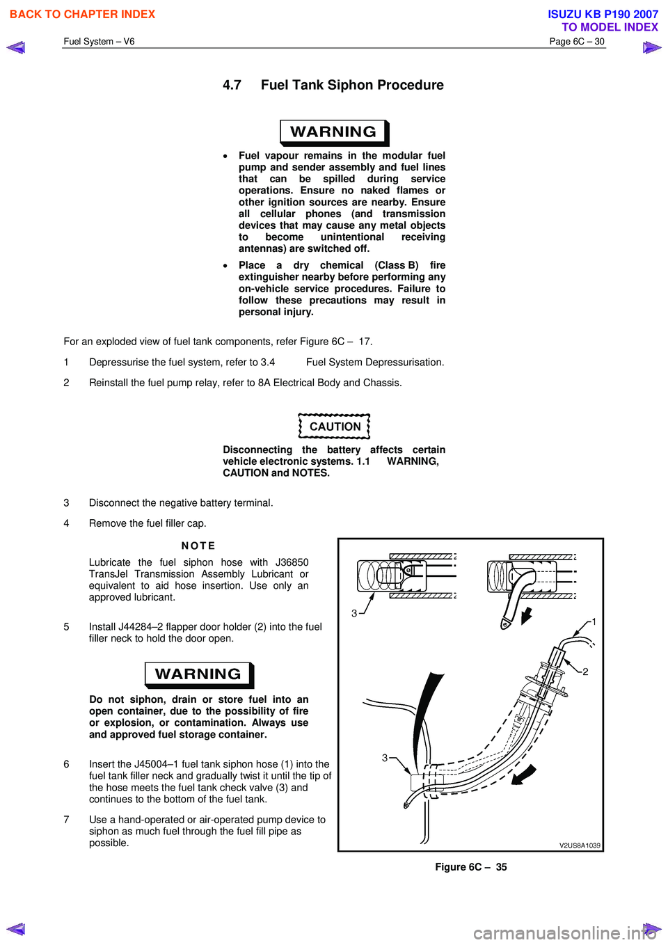
5 Install J44284–2 flapper door holder (2) into the fuel filler neck to hold the door open.
Do not siphon, drain or store fuel into an
open container, due to the possibility of fire
or explosion, or contamination. Always use
and approved fuel storage container.
6 Insert the J45004–1 fuel tank siphon hose (1) into the fuel tank filler neck and gradually twist it until the tip of
the hose meets the fuel tank check valve (3) and
continues to the bottom of the fuel tank.
7 Use a hand-operated or air-operated pump device to siphon as much fuel through the fuel fill pipe as
possible.
Figure 6C – 35
BACK TO CHAPTER INDEX
TO MODEL INDEX
ISUZU KB P190 2007
Page 3235 of 6020
Fuel System – V6 Page 6C – 33
4.9 Fuel Lines
Remove
• A depressurised fuel system contains fuel
in the fuel filter and fuel lines that can be
spilled during service operations.
• Fuel vapour remains in the fuel tank even
when completely empty. Seal all openings
in the fuel tank using suitable material or a
plastic plug. Ensure no naked flames or
other ignition sources are nearby. Ensure
all cellular phones (and transmission
devices that may cause any metal objects
to become unintentional receiving
antennas) are switched off.
• Place a dry chemical (Class B) fire
extinguisher nearby before performing any
on-vehicle service procedures. Failure to
follow these precautions may result in
personal injury.
• Wear safety glasses when using
compressed air. Do not blow compressed
air onto any body part.
1 Remove the fuel pump relay, refer to 8A Electrical Body and Chassis.
2 Depressurise the fuel system, refer to 3.4 Fuel System Depressurisation.
Never drain or store fuel into an open
container, due to the possibility of fire or
explosion.
3 Raise the vehicle, preferably on a hoist, refer to 0A General Information.
Before proceeding, clean all traces of dirt and
other foreign material from the fuel lines.
4 Use compressed air to ensure that all dirt and foreign materials are removed from all fuel connections before the parts are disconnected.
5 If required, remove the stone guard, refer to Figure 6C – 17 and fuel lines. Use the following illustrations showing the fuel line layout and location of other items relating to the fuel system as a guide, also refer to 4.1 Fuel Lines
And Quick Connect Fittings and 4.6 Evaporative Emission Control Canister.
BACK TO CHAPTER INDEX
TO MODEL INDEX
ISUZU KB P190 2007
Page 3245 of 6020
Engine Management – V6 – General Information Page 6C1-1–3
1 General Information
The V6 engine management system
incorporates functions and components that
could cause personal injury or vehicle
damage. Refer to 6C1-2 Engine Management –
V6 – Diagnostics, and 6C1-3 Engine
Management – V6 – Service Operations,
before attempting any diagnosis or repairs.
1.1 Introduction
The V6 engine management system is designed to improve engine performance and increase vehicle safety while
meeting the stringent Euro 3 vehicle emission standard. This is achieved by the introduction of the following engine
management sub-systems and components:
• Throttle actuator control (TAC) System – the TAC system allows the engine control module (ECM) to electronically
control the throttle plate opening eliminating the need for the following components:
• mechanical link between the throttle plate and accelerator pedal,
• cruise control module, and
• idle air control motor.
Refer to 3.5 Throttle Actuator Control System for details of the TAC System operation and to 3.6 Cruise Control System for details of the cruise control operation.
This feature results in improved driveability, better fuel economy and emission control.
• W ide band heated oxygen sensor provides a more accurate measurement of the oxygen concentration in the
exhaust gas. Refer to 4.14 Heated Oxygen Sensors.
• Dual spray fuel injectors are now used. The use of this spray pattern is used in engines with two intake valves per
cylinder. The dual spray is achieved by having two openings in the spray orifice disc that are arranged in such a
way that two fuel sprays result, being aimed at each intake valve port. Refer to 4.12 Fuel Injectors.
• Pencil Coil – allows the ignition coil to be fitted directly on the spark plug eliminating the need for spark plug wires.
Refer to 4.15 Ignition Coil and Spark Plug.
The engine management system has a self diagnostic capability, as well as connections to enable diagnosis of faults. If
the ECM recognises operational problems it can alert the driver via the malfunction indicator lamp (MIL) in the instrument
cluster. The ECM also interfaces with other systems in the vehicle as required.
For further information on the air-conditioning system refer to 2A Heater and Air-conditioning,
For the location of fuses, fusible links and relays, refer to 8A Electrical-Body and Chassis.
1.2 Emission Control
ADR 79/01 Emissions Standards
MY2006 I190 Rodeo has been configured to comply with Australian Design Rule 79/01, that adopts the technical
requirements of the European Council Directive 98/69/EC. Commonly referred to as “Euro 3”, the new legislation
modifies the exhaust emissions, compared to the existing ADR 37/01 (or ‘Euro 2’) vehicle emissions standards.
Australian Design Rule 79/01 implements the 'Euro 3' exhaust and evaporative emissions requirements for petrol fuelled
passenger cars, forward control vehicles and passenger off-road vehicles with a gross vehicle mass (GVM) up to 3.5
tonnes. All new vehicles within these categories and first registered from January 1, 2006 must comply with ADR 79/01.
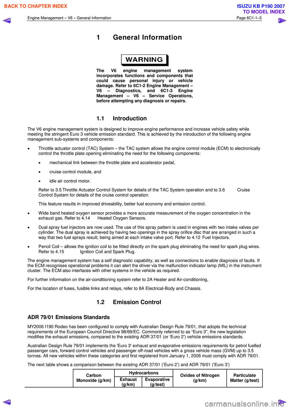
The next table shows a comparison between the existing ADR 37/01 (‘Euro 2’) and ADR 79/01 (‘Euro 3’) Hydrocarbons
Carbon
Monoxide (g/km) Exhaust
(g/km) Evaporative
(g/test) Oxides of Nitrogen
(g/km) Particulate
Matter (g/test)
BACK TO CHAPTER INDEX
TO MODEL INDEX
ISUZU KB P190 2007
Page 3252 of 6020
Engine Management – V6 – General Information Page 6C1-1–10
Fuel Injection System
Each cylinder of the V6 engine is fitted with one fuel injector. The engine control relay applies ignition positive voltage to
the fuel injector ignition circuit. The ECM controls the operation of the fuel injectors by applying a pulse width modulated
(PW M) ground to the fuel injector control circuit to control each fuel injector on-time.
W hile the engine is running, the ECM constantly monitors the various inputs and recalculates the appropriate on-time for
each injector. The calculation is based on the following:
• The injector flow rate,
• Mass of fuel passed by the energised injector per unit of time,
• The desired air / fuel ratio, and
• Actual air mass in each cylinder.
The ECM calculates the duration of the fuel injector on-time to deliver the correct amount of fuel for optimum drivability
and emission control. The period of time the fuel injector is energised is called the injector on-time and is measured in
milliseconds (thousandths of a second).
The V6 engine uses the sequential fuel injection system. Each fuel injector is energised individually at the correct
moment during its firing stroke as the cylinder’s intake valves are closing to provide enough time for the fuel to atomise
completely and mix with the intake air.
Short Term Fuel Trim
The short term fuel trim (STFT) represents the duration of the fuel injector on-time as calculated by the ECM, while the
ECM is in Closed Loop mode. The STFT allows the ECM to calculate the fuel injector on-time based on the heated
oxygen sensor (HO2S) signal input to the ECM. Therefore, the STFT is disabled when the ECM is in Open Loop mode.
• If the air / fuel mixture in the exhaust is balanced (lambda = 1) or when the STFT is disabled, the STFT value is 0%.
• W hen the HO2S sends an input signal to the ECM indicating the air / fuel mixture is rich, the STFT will be less than
0%, which indicates the ECM is decreasing the fuel injector on-time to reduce the amount of fuel in the air / fuel
mixture.
• W hen the HO2S sends an input signal to the ECM indicating the air / fuel mixture is lean, the STFT will be greater
than 0%, which indicates the ECM is increasing the fuel injector on-time to increase the amount of fuel in the air /
fuel mixture.
The percentage values of the STFT range from –25% to +25% and are directly proportional to the duration of the fuel
injector on-time.
Long Term Fuel Trim
The ECM stores the long term fuel trim (LTFT) in its memory to adjust the fuel injector on-time according to the long term
changes or deterioration in the engine components. The normal LTFT value is 0%.
The following describes the LTFT operation when the engine air filter is dirty that causes a restricted intake airflow fault
condition:
1 The HO2S sends an input signal to the ECM the air / fuel mixture is rich because of the reduced airflow. The STFT may reduce to a value of –10%, which decreases the fuel injector on-time to reduce the amount of fuel in the air /
fuel mixture supplied to the engine.
W ithout the use of the LTFT, the restricted airflow caused by the dirty air filter may reduce the STFT value to –10% until the air filter is replaced. This will decrease the range of negative adjustment available to the STFT to
compensate for other factors.
2 W hen the ECM detects the STFT has remained at –10% for a specific period, the ECM switches to the LTFT. The LTFT adjusts the duration of the fuel injector on-time until the air / fuel mixture in the exhaust is balanced (lambda =
1) and the STFT value returns to 0%.
3 The ECM stores this Long Term FT value in its memory, which is used to calculate the base fuel injector on-time.
The percentage values of the Long Term FT range from –100% to +100%. If the ECM detects the LTFT values are
outside the specified percentage range for a predetermined period, the ECM will set a Diagnostic Trouble Code and
switch to Open Loop mode.
BACK TO CHAPTER INDEX
TO MODEL INDEX
ISUZU KB P190 2007
Page 3254 of 6020
Engine Management – V6 – General Information Page 6C1-1–12
Battery Voltage Correction Mode
The ECM monitors the battery voltage circuit to ensure the voltage available to the engine management system stays
within the specified range. A low system voltage changes the voltage across the fuel injectors, which affects the fuel
injector flow rate. In addition, a low system voltage fault condition may cause other engine management system
components to malfunction.
The ECM switches to battery voltage correction mode when the ECM detects a low battery voltage fault condition. W hile
in battery voltage correction mode, the ECM performs the following functions to compensate for the low system voltage:
• Increases the injector on-time to maintain the correct amount of fuel being delivered, and
• Increases the idle speed to increase the generator output.
Limp Mode
The programming in the ECM software allows the engine to run in a back-up fuel strategy or limp mode when the ECM
fails to receive signal inputs from critical sensors or when a critical engine management fault condition exists.
The ECM switches to limp mode to enable the vehicle to be driven until service operations can be performed.
Engine Protection Mode
Engine protection mode is engaged to protect engine components from friction damage in the event of an engine over-
temperature condition being detected by the ECM.
W hen the ECM is in engine protection mode, fuel injectors are systematically disabled and re-activated. The injectors
that have been shut down allow the air being drawn into the engine to assist with engine cooling.
Clear Flood Mode
If the engine is flooded with fuel during starting and will not start, the clear flood mode can be manually selected by
depressing the accelerator pedal to wide open throttle (W OT). In this mode, the ECM will completely disable the fuel
injectors, and will maintain this state during engine cranking as long as the ECM detects a W OT condition with engine
speed less than 1,000 rpm.
3.3 Ignition Control System
The electronic ignition system provides a spark to ignite the compressed air / fuel mixture at the correct time. The ECM
maintains correct spark timing and dwell for all engine operating conditions. The ECM calculates the optimum spark
parameters from information received from the various sensors and triggers the appropriate ignition module / coil to fire
the spark plug.
3.4 Starter Motor Operation
The engine control module controls the activation of the start relay in response to inputs from:
• Ignition switch,
• Battery,
• Immobiliser system, and
• Automatic transmission gear selector position / clutch pedal position switch for vehicles with manual transmissions.
3.5 Throttle Actuator Control System
Description
The throttle actuator control (TAC) system is used to improve emissions, fuel economy and driveability. The TAC system
eliminates the mechanical link between the accelerator pedal and the throttle plate and eliminates the need for a cruise
control module and idle air control motor. The TAC system comprises of:
BACK TO CHAPTER INDEX
TO MODEL INDEX
ISUZU KB P190 2007
Page 3264 of 6020
Engine Management – V6 – General Information Page 6C1-1–22
4.6 Clutch Pedal Switch Assembly – Manual
Vehicles Only
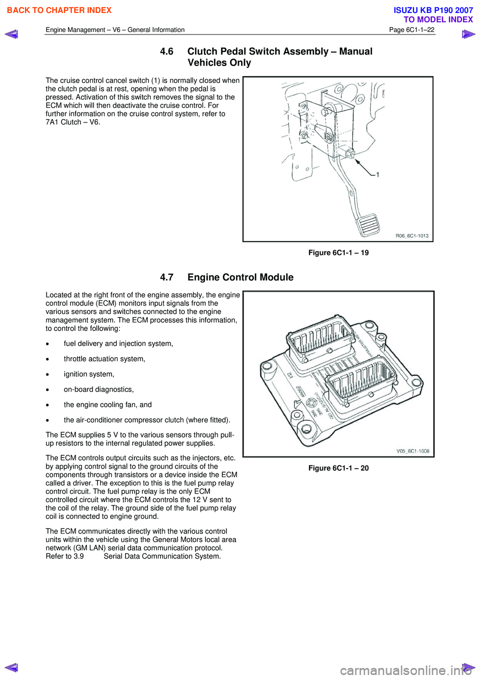
The cruise control cancel switch (1) is normally closed when
the clutch pedal is at rest, opening when the pedal is
pressed. Activation of this switch removes the signal to the
ECM which will then deactivate the cruise control. For
further information on the cruise control system, refer to
7A1 Clutch – V6.
Figure 6C1-1 – 19
4.7 Engine Control Module
Located at the right front of the engine assembly, the engine
control module (ECM) monitors input signals from the
various sensors and switches connected to the engine
management system. The ECM processes this information,
to control the following:
• fuel delivery and injection system,
• throttle actuation system,
• ignition system,
• on-board diagnostics,
• the engine cooling fan, and
• the air-conditioner compressor clutch (where fitted).
The ECM supplies 5 V to the various sensors through pull-
up resistors to the internal regulated power supplies.
The ECM controls output circuits such as the injectors, etc.
by applying control signal to the ground circuits of the
components through transistors or a device inside the ECM
called a driver. The exception to this is the fuel pump relay
control circuit. The fuel pump relay is the only ECM
controlled circuit where the ECM controls the 12 V sent to
the coil of the relay. The ground side of the fuel pump relay
coil is connected to engine ground.
The ECM communicates directly with the various control
units within the vehicle using the General Motors local area
network (GM LAN) serial data communication protocol.
Refer to 3.9 Serial Data Communication System.
Figure 6C1-1 – 20
BACK TO CHAPTER INDEX
TO MODEL INDEX
ISUZU KB P190 2007
Page 3278 of 6020
Engine Management – V6 – General Information Page 6C1-1–36
Intermittent
An electrical signal that occurs now and then; not continuously. In electrical circuits, refers to occasional open,
short, or ground in a circuit
Light Throttle Approximately 1/4 of accelerator pedal travel (25% throttle position)
Low
A voltage less than a specific threshold. Operates the same as a ground and may, or may not, be connected
to chassis ground.
MAF Sensor Mass Air Flow Sensor. A device that provides a variable voltage to the ECM based on the amount of air flow
entering in the intake system.
Medium Throttle Approximately 1/2 of accelerator pedal travel (50% throttle position)
N.C Normally Closed. Switch contacts that are closed when they are in the normal operating position
N.O Normally Open. Switch contacts that are normally open when in the normal operating position
NOx
Nitrogen Oxide. One of the pollutants found in spark ignition engine exhaust that is formed from normal
combustion and increases in severity with combustion temperature.
O2 Sensor Oxygen Sensor. A device located in the exhaust system that provides a variable voltage to the ECM based on
the oxygen content of exhaust gas.
May also include a heating circuit to provide faster initial warm-up (HO2 sensor).
OBD On Board Diagnostic
Open Loop ECM control of the fuel control system without the use of the oxygen sensor signal.
Output Functions that are controlled by the ECM, typically these can include solenoids and relays, etc.
ECM Engine Control Module. An electronic device which controls the engine management system.
ECU Electronic Control Unit. An electronic device which controls specific system functions
PCV
Positive Crankcase Ventilation. Method of reburning crankcase fumes rather than passing them directly into
the atmosphere
PIM Powertrain Interface Module – The PIM acts as a communication translator between the ECM and other on-
board controllers that use a different serial data protocol.
PM Permanent Magnet
PWM
Pulse Width Modulated. A digital signal turned on and off for a percentage of available cycle time. A signal that
is 30% on and 70% of would be termed a 30% on PWM signal.
Quad Driver A transistor in the ECM capable of operating four separate outputs. Outputs can be either on-off or pulse width
modulated.
RAM Random Access Memory. A microprocessor can write into or read from this memory as needed. This memory
is volatile and needs a constant power supply to be retained. If the power is lost or removed, RAM data is lost.
r.p.m. Revolutions Per Minute
Serial Data
Serial data is a series of rapidly changing voltage signals pulsed from high to low. These signals are typically
transmitted through a wire often referred to as the Serial Data Circuit.
SFI Sequential Fuel Injection. Method of injecting fuel into the engine one cylinder at a time in relation to the
engines firing order.
Solenoid An electromagnetic coil which creates a magnetic field when current is applied, causing a plunger or ball to
move.
Switch Device to opens and close a circuit, thereby controlling current flow.
Tech 2
Tech 2 is a peripheral device that aids in the diagnosis and repair of electronic systems such as engine
management, transmission control etc. Tech 2 connects to the vehicle’s Data Link Connector (DLC).
TP Sensor Throttle Position sensor. A device that provides a variable voltage to the ECM based on the position of the
throttle plate.
Vacuum – manifold Vacuum sourced downstream of the throttle plate.
Vacuum – ported Vacuum sourced upstream of the throttle plate.
VSS Vehicle Speed Sensor. A permanent magnet type device that provides a digital voltage to the ECM.
WOT Wide Open Throttle – Full travel of the accelerator pedal (100% throttle position).
BACK TO CHAPTER INDEX
TO MODEL INDEX
ISUZU KB P190 2007