relay ISUZU KB P190 2007 Workshop Repair Manual
[x] Cancel search | Manufacturer: ISUZU, Model Year: 2007, Model line: KB P190, Model: ISUZU KB P190 2007Pages: 6020, PDF Size: 70.23 MB
Page 2130 of 6020

6C-12 ENGINE FUEL (C24SE)
Fuel Pump Relay
General Description
In order to control the fuel pump and sender assembly
(FPAS) operation, the FPAS relay is provided. W hen
the starter switch is turned to “ON" position, the FPAS
relay operates the FPAS for 2 seconds.
W hen it is turned to “START" position, the Engine
Control Module receives the reference pulse from the
Ignition Control Module and it operates the relay, again
causing the FPAS to feed fuel.
BACK TO CHAPTER INDEX
TO MODEL INDEX
ISUZU KB P190 2007
Page 2150 of 6020

6D3-2 STARTING AND CHARGING SYSTEM
Starting System
General Description
Cranking Circuit
The cranking system consists of a battery, starter, starter
switch, starter relay, etc. These main components are
connected.
Starter
The cranking system employs a magnetic type reduction
starter in which the motor shaft is also used as a pinion shaft.
W hen the starter switch is turned on, the contacts of magnetic
switch are closed, and the armature rotates. At the same time,
the plunger is attracted, and the pinion is pushed forward by
the shift lever to mesh with the ring gear.
Then, the ring gear runs to start the engine. W hen the engine
starts and the starter switch is turned off, the plunger returns,
the pinion is disengaged from the ring gear, and the armature
stops rotation. W hen the engine speed is higher than the
pinion, the pinion idles, so that the armature is not driven.
Service Precaution
CAUTION:
Always use the correct fastener in the proper location.
When you replace a fastener, use ONLY the exact part
number for that application. ISUZU will call out those
fasteners that require a replacement after removal. ISUZU
will also call out the fasteners that require thread lockers
or thread sealant. UNLESS OTHERWISE SPECIFIED, do
not use supplemental coatings (Paints, greases, or other
corrosion inhibitors) on threaded fasteners or fastener
joint interfaces. Generally, such coatings adversely affect
the fastener torque and the joint clamping force, and may
damage the fastener. When you install fasteners, use the
correct tightening sequence and specifications. Following
these instructions can help you avoid damage to parts
and systems.
Diagnosis
Condition Possible cause Correction
Starter does not run Charging failure Repair charging system
Battery Failure Replace Battery
Terminal connection failure Repair or replace terminal connector
and/or wiring harness
Starter switch failure Repair or replace starter switch
Starter failure Repair or replace starter
BACK TO CHAPTER INDEX
TO MODEL INDEX
ISUZU KB P190 2007
Page 2171 of 6020
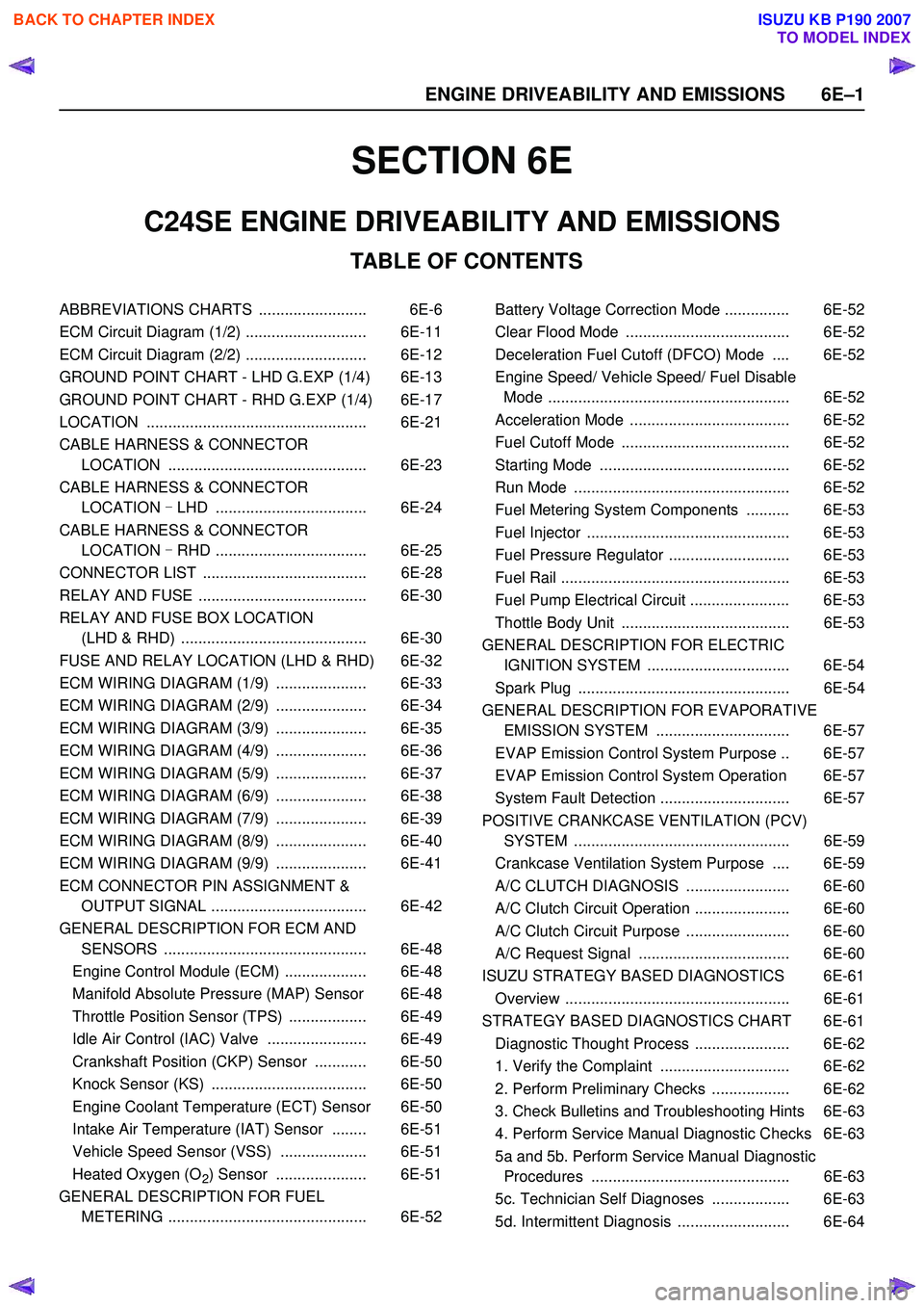
SECTION 6E
TABLE OF CONTENTS
C24SE ENGINE DRIVEABILITY AND EMISSIONS
ABBREVIATIONS CHARTS ......................... 6E-6
ECM Circuit Diagram (1/2) ............................ 6E-11
ECM Circuit Diagram (2/2) ............................ 6E-12
GROUND POINT CHART - LHD G.EXP (1/4) 6E-13
GROUND POINT CHART - RHD G.EXP (1/4) 6E-17
LOCATION ................................................... 6E-21
CABLE HARNESS & CONNECTOR LOCATION .............................................. 6E-23
CABLE HARNESS & CONNECTOR LOCATION - LHD ................................... 6E-24
CABLE HARNESS & CONNECTOR LOCATION - RHD ................................... 6E-25
CONNECTOR LIST ...................................... 6E-28
RELAY AND FUSE ....................................... 6E-30
RELAY AND FUSE BOX LOCATION (LHD & RHD) ........................................... 6E-30
FUSE AND RELAY LOCATION (LHD & RHD) 6E-32
ECM WIRING DIAGRAM (1/9) ..................... 6E-33
ECM WIRING DIAGRAM (2/9) ..................... 6E-34
ECM WIRING DIAGRAM (3/9) ..................... 6E-35
ECM WIRING DIAGRAM (4/9) ..................... 6E-36
ECM WIRING DIAGRAM (5/9) ..................... 6E-37
ECM WIRING DIAGRAM (6/9) ..................... 6E-38
ECM WIRING DIAGRAM (7/9) ..................... 6E-39
ECM WIRING DIAGRAM (8/9) ..................... 6E-40
ECM WIRING DIAGRAM (9/9) ..................... 6E-41
ECM CONNECTOR PIN ASSIGNMENT & OUTPUT SIGNAL .................................... 6E-42
GENERAL DESCRIPTION FOR ECM AND SENSORS ............................................... 6E-48
Engine Control Module (ECM) ................... 6E-48
Manifold Absolute Pressure (MAP) Sensor 6E-48
Throttle Position Sensor (TPS) .................. 6E-49
Idle Air Control (IAC) Valve ....................... 6E-49
Crankshaft Position (CKP) Sensor ............ 6E-50
Knock Sensor (KS) .................................... 6E-50
Engine Coolant Temperature (ECT) Sensor 6E-50
Intake Air Temperature (IAT) Sensor ........ 6E-51
Vehicle Speed Sensor (VSS) .................... 6E-51
Heated Oxygen (O
2) Sensor ..................... 6E-51
GENERAL DESCRIPTION FOR FUEL METERING .............................................. 6E-52 Battery Voltage Correction Mode ............... 6E-52
Clear Flood Mode ...................................... 6E-52
Deceleration Fuel Cutoff (DFCO) Mode .... 6E-52
Engine Speed/ Vehicle Speed/ Fuel Disable Mode ........................................................ 6E-52
Acceleration Mode ..................................... 6E-52
Fuel Cutoff Mode ....................................... 6E-52
Starting Mode ............................................ 6E-52
Run Mode .................................................. 6E-52
Fuel Metering System Components .......... 6E-53
Fuel Injector ............................................... 6E-53
Fuel Pressure Regulator ............................ 6E-53
Fuel Rail ..................................................... 6E-53
Fuel Pump Electrical Circuit ....................... 6E-53
Thottle Body Unit ....................................... 6E-53
GENERAL DESCRIPTION FOR ELECTRIC IGNITION SYSTEM ................................. 6E-54
Spark Plug ................................................. 6E-54
GENERAL DESCRIPTION FOR EVAPORATIVE EMISSION SYSTEM ............................... 6E-57
EVAP Emission Control System Purpose .. 6E-57
EVAP Emission Control System Operation 6E-57
System Fault Detection .............................. 6E-57
POSITIVE CRANKCASE VENTILATION (PCV) SYSTEM .................................................. 6E-59
Crankcase Ventilation System Purpose .... 6E-59
A/C CLUTCH DIAGNOSIS ........................ 6E-60
A/C Clutch Circuit Operation ...................... 6E-60
A/C Clutch Circuit Purpose ........................ 6E-60
A/C Request Signal ................................... 6E-60
ISUZU STRATEGY BASED DIAGNOSTICS 6E-61
Overview .................................................... 6E-61
STRATEGY BASED DIAGNOSTICS CHART 6E-61 Diagnostic Thought Process ...................... 6E-62
1. Verify the Complaint .............................. 6E-62
2. Perform Preliminary Checks .................. 6E-62
3. Check Bulletins and Troubleshooting Hints 6E-63
4. Perform Service Manual Diagnostic Checks 6E-63
5a and 5b. Perform Service Manual Diagnostic Procedures .............................................. 6E-63
5c. Technician Self Diagnoses .................. 6E-63
5d. Intermittent Diagnosis .......................... 6E-64
6 E –1
E N GINE DRIV EABILITY AND E M IS SIONS
BACK TO CHAPTER INDEX
TO MODEL INDEX
ISUZU KB P190 2007
Page 2199 of 6020
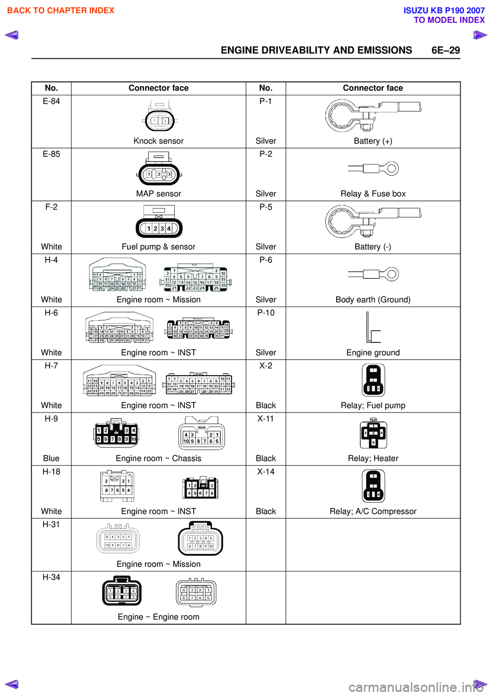
ENGINE DRIVEABILITY AND EMISSIONS 6E–29
No.Connector face No.Connector face
E-84
Knock sensor P-1
Silver Battery (+)
E-85
MAP sensor P-2
Silver Relay & Fuse box
F-2
White Fuel pump & sensor P-5
Silver Battery (-)
H-4
White Engine room ~ Mission P-6
Silver Body earth (Ground)
H-6
White Engine room ~ INST P-10
Silver Engine ground
H-7
White Engine room ~ INST X-2
Black Relay; Fuel pump
H-9
Blue Engine room ~ Chassis X-11
Black Relay; Heater
H-18
White Engine room ~ INST X-14
Black Relay; A/C Compressor
H-31
Engine room ~ Mission
H-34
Engine ~ Engine room
BACK TO CHAPTER INDEX
TO MODEL INDEX
ISUZU KB P190 2007
Page 2200 of 6020
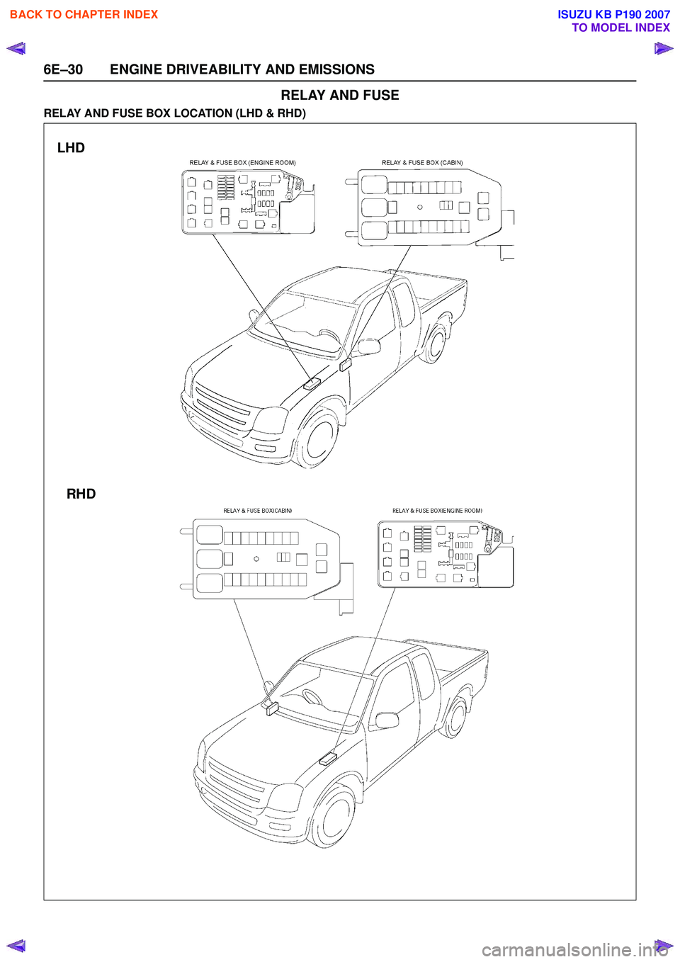
6E–30 ENGINE DRIVEABILITY AND EMISSIONS
RELAY AND FUSE
RELAY AND FUSE BOX LOCATION (LHD & RHD)
LHDRHD
BACK TO CHAPTER INDEX
TO MODEL INDEX
ISUZU KB P190 2007
Page 2201 of 6020
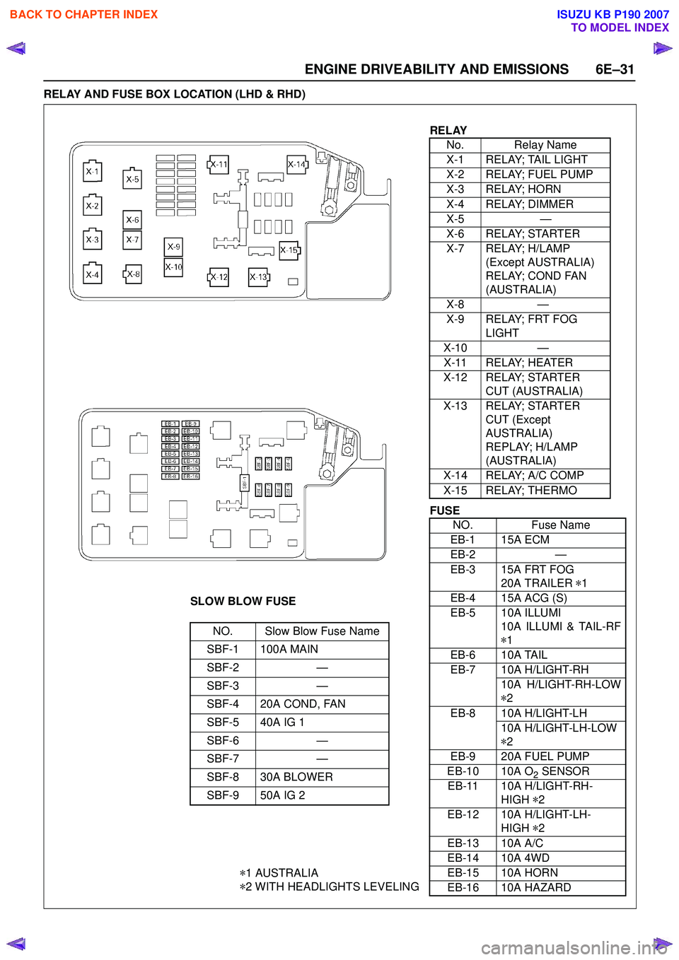
ENGINE DRIVEABILITY AND EMISSIONS 6E–31
RELAY AND FUSE BOX LOCATION (LHD & RHD)
RELAYNo. Relay Name
X-1 RELAY; TAIL LIGHT
X-2 RELAY; FUEL PUMP
X-3 RELAY; HORN
X-4 RELAY; DIMMER
X-5 —
X-6 RELAY; STARTER
X-7 RELAY; H/LAMP (Except AUSTRALIA)
RELAY; COND FAN
(AUSTRALIA)
X-8 —
X-9 RELAY; FRT FOG LIGHT
X-10 —
X-11 RELAY; HEATER
X-12 RELAY; STARTER CUT (AUSTRALIA)
X-13 RELAY; STARTER CUT (Except
AUSTRALIA)
REPLAY; H/LAMP
(AUSTRALIA)
X-14 RELAY; A/C COMP
X-15 RELAY; THERMO
SLOW BLOW FUSE
NO. Slow Blow Fuse Name
SBF-1 100A MAIN
SBF-2 —
SBF-3 —
SBF-4 20A COND, FAN
SBF-5 40A IG 1
SBF-6 —
SBF-7 —
SBF-8 30A BLOWER
SBF-9 50A IG 2
* 1 AUSTRALIA
* 2 WITH HEADLIGHTS LEVELING
FUSE
NO. Fuse Name
EB-1 15A ECM
EB-2 —
EB-3 15A FRT FOG 20A TRAILER *1
EB-4 15A ACG (S)
EB-5 10A ILLUMI 10A ILLUMI & TAIL-RF
* 1
EB-6 10A TAIL
EB-7 10A H/LIGHT-RH 10A H/LIGHT-RH-LOW
* 2
EB-8 10A H/LIGHT-LH 10A H/LIGHT-LH-LOW
* 2
EB-9 20A FUEL PUMP
EB-10 10A O
2 SENSOR
EB-11 10A H/LIGHT-RH- HIGH *2
EB-12 10A H/LIGHT-LH- HIGH *2
EB-13 10A A/C
EB-14 10A 4WD
EB-15 10A HORN
EB-16 10A HAZARD
BACK TO CHAPTER INDEX
TO MODEL INDEX
ISUZU KB P190 2007
Page 2202 of 6020
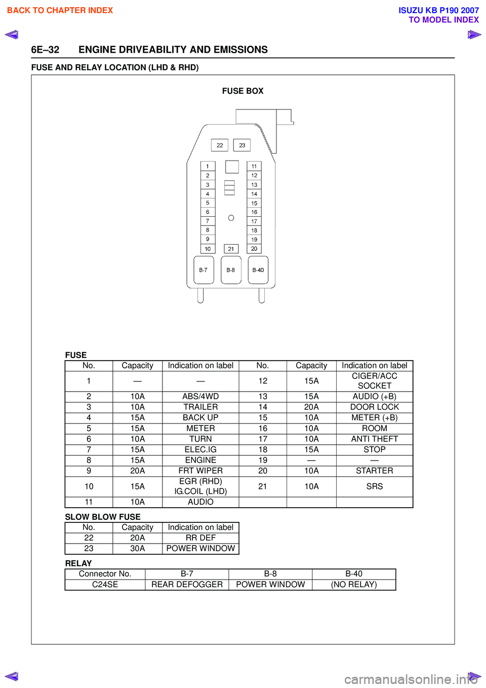
6E–32 ENGINE DRIVEABILITY AND EMISSIONS
FUSE AND RELAY LOCATION (LHD & RHD)
FUSE
SLOW BLOW FUSE
RELAY No. Capacity Indication on label No. Capacity Indication on label
1— — 1 215A CIGER/ACC
SOCKET
2 10A ABS/4WD 13 15A AUDIO (+B)
3 10A TRAILER 14 20A DOOR LOCK
4 15A BACK UP 15 10A METER (+B)
5 15A METER16 10A ROOM
6 10A TURN17 10A ANTI THEFT
7 15A ELEC.IG 18 15ASTOP
815A ENGINE 19 — —
9 20A FRT WIPER 20 10A STARTER
10 15A EGR (RHD)
IG.COIL (LHD) 21 10A
SRS
11 10A AUDIO
No. Capacity Indication on label 22 20A RR DEF
23 30A POWER WINDOW
Connector No. B-7B-8B-40
C24SE REAR DEFOGGER POWER WINDOW (NO RELAY)
FUSE BOX
BACK TO CHAPTER INDEX
TO MODEL INDEX
ISUZU KB P190 2007
Page 2214 of 6020

6E–44 ENGINE DRIVEABILITY AND EMISSIONS
Connector J2 Port: View Looking Into ECM Case
1
17 16
32
PIN32
PIN1
PIN17
PIN16
Pin
No. B/
Box No. Pin Function
Wire
Color Signal or Continuity
ECM
Connection Tester Position
Key SW Off Key SW
On Engine
Idle Engine
2000rpm Range (+) (-)
J2-1 J2-1 Intake Air Temp. (IAT) Sensor Ground GRN Continuity
with
ground -
- - Disconnect ΩJ2-1 GND
J2-2 J2-2 Battery Power Supply RED/ WHT10-14V
Connect DC V J2-2 GND
J2-3 J2-3 Ignition Power Supply BLU/ YELLess than
1V 10-14V
Connect DC V J2-3 GND
J2-4 J2-4 To Data Link Connector No. 6 BLU -
-- - -- - -
J2-5 J2-5 No Connection -- - - - -- - -
J2-6 J2-6 Oxygen Sensor (Ground) PNK Continuity
with
ground -
- - Connect ΩJ2-6 GND
J2-7 J2-7 No Connection -- - - - -- - -
J2-8 J2-8 No Connection -- - - - -- - -
J2-9 J2-9 No Connection -- - - - -- - -
J2-10 J2-10 CO Adjust Signal (W/O Catalystic
Converter) YEL -
-- - -- - -
J2-11 J2-11 Fuel Pump Relay GRN/ WHT10-14V
While relay
is activated; 10-14V
Relay is not
activated;
Less than 1V10-14V Connect DC V J2-11 GND
J2-12 J2-12 No Connection -- - - - -- - -
J2-13 J2-13 A/C Compressor Relay GRY/
RED Less than
1V A/C comp. is operated: Less than 1V
A/C comp. is not operated: 10-14V Connect DC V J2-13 GND
J2-14 J2-14 No Connection -- - - - -- - -
J2-15 J2-15 No Connection -- - - - -- - -
J2-16 J2-16 No Connection -- - - - -- - -
J2-17 J2-17 CO Adjust (W/O Catalystic Converter) RED -
-- - -- - -
J2-18 J2-18 Battery Power Supply RED/ WHT10-14V
Connect DC V J2-18 GND
J2-19 J2-19 No Connection -- - - - -- - -
J2-20 J2-20 Power Steering Pressure Switch GRN/
YEL Less than
1V
Pressure switch is turned on: Less than 1VPressure switch is turned off: 10-14VConnect DC V J2-20 GND
J2-21 J2-21 Oxygen Sensor BLU Less than 1VApprox.
0.4V Wave form D or 0.1 -
0.9V Connect DC V J2-21 J2-6
J2-22 J2-22 Intake Air Temp. (IAT) Sensor (Signal) YEL/
GRN Less than
1V
20℃: Approx. 2.9V / 40 ℃: Approx. 1.8V V
/ 60 ℃: Approx. 1.1V / 80 ℃: Approx. 0.6VConnect DC V J2-22 33
BACK TO CHAPTER INDEX
TO MODEL INDEX
ISUZU KB P190 2007
Page 2215 of 6020

ENGINE DRIVEABILITY AND EMISSIONS 6E–45
J2-23 J2-23 Vehicle Speed Sensor (VSS) Signal
(Immobilizer Control
Unit Terminal B8) WHT -
- Wave form C or Approx.
6.5V at 20km/h Connect AC V J2-23 GND
J2-24 J2-24 No Connection -- - - - -- - -
J2-25 J2-25 Tachometer Output Signal BLK/
RED -
- Wave form Wave form
B or
Approx.
4.5V Connect AC V J2-25 GND
J2-26 J2-26 Thermo Relay GRN/
BLK Less than
1V
A/C request is activated: 10-14V
A/C request is not activated: Less than 1VConnect DC V J2-26 GND
J2-27 J2-27 No Connection - - - - - - - - -
J2-28 J2-28 No Connection - - - - - - - - -
J2-29 J2-29 No Connection -- - - - -- - -
J2-30 J2-30 To Data Link Connector No. 2 GRN -
-- - -- - -
J2-31 J2-31 Oxygen Sensor Heater BLU/ WHTContinuity
with
ground - Wave
Form Wave
Form D Connect
ΩJ2-31 GND
J2-32 J2-32 Check Engine Lamp (Immobilizer Control
Unit Terminal B7) BRN/
YEL Less than
1V Less than
1V Lamp is turned on: Less
than 1V
Lamp is turned off: 10-
14V Connect DC V J2-32 GND
Pin
No. B/
Box No. Pin Function
Wire
Color Signal or Continuity
ECM
Connection Tester Position
Key SW Off Key SW
On Engine
Idle Engine
2000rpm Range (+) (-)
BACK TO CHAPTER INDEX
TO MODEL INDEX
ISUZU KB P190 2007
Page 2222 of 6020
6E–52 ENGINE DRIVEABILITY AND EMISSIONS
GENERAL DESCRIPTION FOR FUEL
METERING
The fuel metering system starts with the fuel in the fuel
tank. An electric fuel pump, located in the fuel tank,
pumps fuel to the fuel rail through an in-line fuel filter.
The pump is designed to provide fuel at a pressure
above the pressure needed by the injectors.
A fuel pressure regulator in the fuel rail keeps fuel
available to the fuel injectors at a constant pressure.
A return line delivers unused fuel back to the fuel tank.
The basic function of the air/fuel metering system is to
control the air/fuel delivery to the engine. Fuel is
delivered to the engine by individual fuel injectors
mounted in the intake manifold.
The main control sensor is the heated oxygen sensor
located in the exhaust system. The heated oxygen
sensor reports to the ECM how much oxygen is in the
exhaust gas. The ECM changes the air/fuel ratio to the
engine by controlling the amount of time that fuel
injector is “On”.
The best mixture to minimize exhaust emissions is 14.7
parts of air to 1 part of gasoline by weight, which allows
the catalytic converter to operate most efficiently.
Because of the constant measuring and adjusting of the
air/fuel ratio, the fuel injection system is called a “closed
loop” system.
The ECM monitors signals from several sensors in
order to determine the fuel needs of the engine. Fuel is
delivered under one of several conditions called “mode”.
All modes are controlled by the ECM.
Battery Voltage Correction Mode
When battery voltage is low, the ECM will compensate
for the weak spark by increasing the following:
• The amount of fuel delivered.
• The idle RPM.
Clear Flood Mode
Clear a flooded engine by pushing the accelerator pedal
down all the way. The ECM then de-energizes the fuel
injectors. The ECM holds the fuel injectors de-energized
as long as the throttle remains above 75% and the
engine speed is below 800 RPM. If the throttle position
becomes less than 75%, the ECM again begins to pulse
the injectors ON and OFF, allowing fuel into the
cylinders.
Deceleration Fuel Cutoff (DFCO) Mode
The ECM reduces the amount of fuel injected when it
detects a decrease in the throttle position and the air
flow. When deceleration is very fast, the ECM may cut
off fuel completely. Until enable conditions meet the
engine revolution less 1000 rpm or manifold absolute
pressure less than 10 kPa.
Engine Speed/ Vehicle Speed/ Fuel Disable
Mode
The ECM monitors engine speed. It turns off the fuel
injectors when the engine speed increases above 6000
RPM. The fuel injectors are turned back on when
engine speed decreases below 3500 RPM.
Acceleration Mode
The ECM provides extra fuel when it detects a rapid
increase in the throttle position and the air flow.
Fuel Cutoff Mode
No fuel is delivered by the fuel injectors when the
ignition is OFF. This prevents engine run-on. In addition,
the ECM suspends fuel delivery if no reference pulses
are detected (engine not running) to prevent engine
flooding.
Starting Mode
When the ignition is first turned ON, the ECM energizes
the fuel pump relay for two seconds to allow the fuel
pump to build up pressure. The ECM then checks the
engine coolant temperature (ECT) sensor and the
throttle position sensor to determine the proper air/fuel
ratio for starting.
The ECM controls the amount of fuel delivered in the
starting mode by adjusting how long the fuel injectors
are energized by pulsing the injectors for very short
times.
Run Mode
The run mode has the following two conditions:
• Open loop
• Closed loop
When the engine is first started, the system is in “open
loop” operation. In “Open Loop,” the ECM ignores the
signal from the heated oxygen sensor (HO2S). It
calculates the air/fuel ratio based on inputs from the TP,
ECT, and MAP sensors.
The system remains in “Open Loop” until the following
conditions are met:
• The HO2S has a varying voltage output showing that it is hot enough to operate properly (this depends on
temperature).
• The ECT has reached a specified temperature.
• A specific amount of time has elapsed since starting the engine.
• Engine speed has been greater than a specified RPM since start-up.
The specific values for the above conditions vary with
different engines and are stored in the programmable
read only memory (PROM). When these conditions are
met, the system enters “closed loop” operation. In
“closed loop,” the ECM calculates the air/fuel ratio
(injector on-time) based on the signal from the HO2S.
This allows the air/fuel ratio to stay very close to 14.7:1.
BACK TO CHAPTER INDEX
TO MODEL INDEX
ISUZU KB P190 2007