ISUZU KB P190 2007 Workshop Repair Manual
Manufacturer: ISUZU, Model Year: 2007, Model line: KB P190, Model: ISUZU KB P190 2007Pages: 6020, PDF Size: 70.23 MB
Page 1981 of 6020

6E-364 ENGINE CONTROL SYSTEM (4JK1/4JJ1)
Fuel Injection System Description
Fuel Injection Quantity Control
This control determines the fuel injection quantity by
adding coolant temperature, fuel temperature, intake
air temperature, barometric pressure, mass air flow and
some switch inputs information corrections to the basic
injection quantity is calculated by the ECM based on
the engine operating conditions (engine speed,
accelerator pedal pressing amount and boost pressure
sensor). More fuel rate indicates if the engine load is
increased as the accelerator pedal is stepped on at
constant engine speed.
Combined with high pressure injection of atomized fuel,
this control improves exhaust gas and ensures proper
fuel consumption. Compared with conventional
mechanical governors, an electronic control system
provides higher degree of freedom of fuel injection
quantity control, thereby presenting high accelerator
response (acceleration feeling and pressing feeling).
Starting Injection Quantity Control
At the engine starting (after the key switch is turned to
the START position to start the engine, up to return of
key switch to the ON position), optimum fuel injection
quantity is controlled based on the information on the
engine speed and coolant temperature. At low
temperature, the fuel injection quantity increases.
When the engine started completely, this boosted
quantity mode at the starting is cancelled and normal
running mode is restored.
Idle Speed Control
A control is made so as to achieve stable idling speed
at all time regardless of engine secular changes or
engine condition variations. The ECM sets target idling
speed and controls the fuel injection quantity according
to the engine conditions (actual engine speed, coolant
temperature and engine load) to follow actual engine
speed to the target idling speed so as to ensure stable
idling speed.
Idle Vibration Control
A control is made so as to reduce the engine vibration
caused by torque variations between cylinders due to
variations in fuel injection quantity of each cylinder or
injector performance. The ECM corrects the injection
quantity between cylinders based on the revolution
signals from the crankshaft position (CKP) sensor.
Normal range of correction quantity between cylinders
is within ±5 mm
3.
BACK TO CHAPTER INDEX
TO MODEL INDEX
ISUZU KB P190 2007
Page 1982 of 6020

ENGINE CONTROL SYSTEM (4JK1/4JJ1) 6E-365
Exhaust Gas Recirculation (EGR) System Description
Legend1. EGR cooler
2. Engine coolant outlet
3. Engine coolant inlet
4. EGR valve 5. ECM
6. MAF sensor
7. Intake throttle valve
The EGR system recirculates a part of exhaust gas
back into the intake manifold, which results in reducing
nitrogen oxide (NOx) emissions. The EGR control
system uses an electronic control system to ensure
both driveability and low emission. A control current
from the ECM operates a solenoid to control the lift
amount of EGR valve. Also, an EGR position sensor is
provided at the rear of the motor to feed actual valve lift
amount back to the ECM for more precision control of
the EGR amount.
The EGR control starts when the conditions for engine
speed, engine coolant temperature, intake air
temperature and barometric pressure are satisfied.
Then, the valve opening is calculated according to the
engine speed, and target fuel injection quantity. Based
on this valve opening, the drive duty of the solenoid is
determined and the valve is driven accordingly. The
intake throttle valve is provided to adequate intake
manifold depression to ensure EGR gas flow. EGR Valve
RTW56EMF001701
1
4
7 5
6
23
RTW56ESH000801
BACK TO CHAPTER INDEX
TO MODEL INDEX
ISUZU KB P190 2007
Page 1983 of 6020
6E-366 ENGINE CONTROL SYSTEM (4JK1/4JJ1)
The EGR valve is mounted on the intake manifold. The
ECM controls the EGR valve opening based on the
engine running condition. The ECM controls the EGR
valve by controlling the solenoid. The solenoid is
controlled based on pulse width modulation (PWM)
signal sent from the ECM. A duty ratio change 0% to
appropriate percentage is EGR valve lift control. To
open the valve, duty ratio is increased. To close the
valve, duty ratio becomes small.
The EGR valve position is detected by the position
sensor, and relayed to the ECM. The position sensor
provides a signal to the ECM on the signal circuit,
which is relative to the position changes of the EGR
valve. The ECM should detect a low signal voltage at a
small lift amount or closed position. The ECM should
detect high signal voltage at a large lift amount.
Intake Throttle Valve
The intake throttle valve is located on the intake
manifold inlet. The ECM controls the intake throttle
valve opening based on the engine running condition.
The ECM controls the intake throttle valve by
controlling the solenoid. The solenoid is controlled
based on pulse width modulation (PWM) signal sent
from the ECM. A duty ratio change 0% to appropriate
percentage is intake throttle valve opening angle
control. To open the valve, duty ratio is increased. To
close the valve, duty ratio becomes small.
The intake throttle valve position is detected by the
position sensor, and relayed to the ECM. The position
sensor provides a signal to the ECM on the signal
circuit, which is relative to the position changes of the
intake throttle valve. The ECM should detect a low
signal voltage at a small opening amount or closed
position. The ECM should detect high signal voltage at
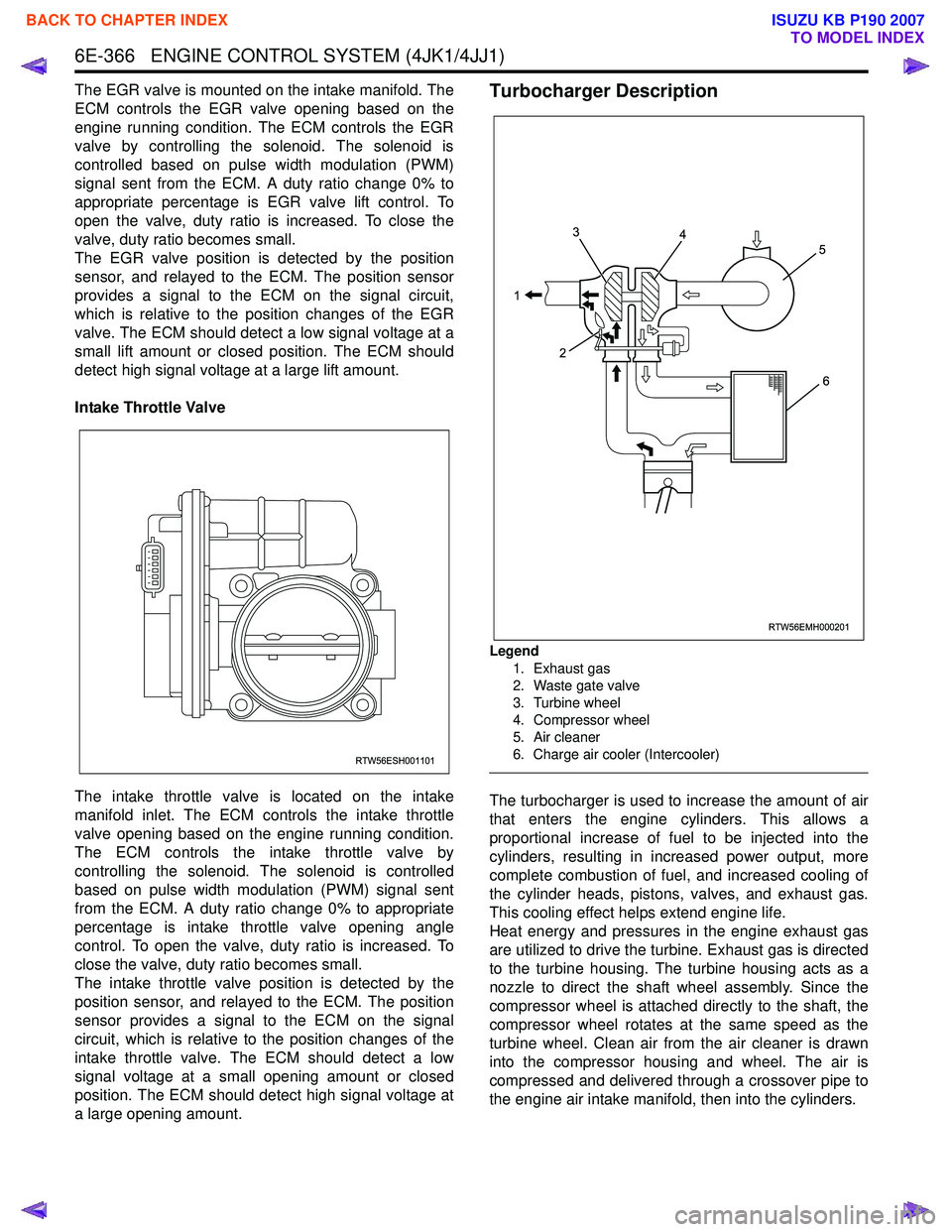
a large opening amount.Turbocharger Description
Legend
1. Exhaust gas
2. Waste gate valve
3. Turbine wheel
4. Compressor wheel
5. Air cleaner
6. Charge air cooler (Intercooler)
The turbocharger is used to increase the amount of air
that enters the engine cylinders. This allows a
proportional increase of fuel to be injected into the
cylinders, resulting in increased power output, more
complete combustion of fuel, and increased cooling of
the cylinder heads, pistons, valves, and exhaust gas.
This cooling effect helps extend engine life.
Heat energy and pressures in the engine exhaust gas
are utilized to drive the turbine. Exhaust gas is directed
to the turbine housing. The turbine housing acts as a
nozzle to direct the shaft wheel assembly. Since the
compressor wheel is attached directly to the shaft, the
compressor wheel rotates at the same speed as the
turbine wheel. Clean air from the air cleaner is drawn
into the compressor housing and wheel. The air is
compressed and delivered through a crossover pipe to
the engine air intake manifold, then into the cylinders.
RTW56ESH001101
RTW56EMH000201
1 3
2 4
5
6
BACK TO CHAPTER INDEX
TO MODEL INDEX
ISUZU KB P190 2007
Page 1984 of 6020
ENGINE CONTROL SYSTEM (4JK1/4JJ1) 6E-367
The amount of air pressure rise and air volume
delivered to the engine from the compressor outlet is
regulated by a waste gate valve in the exhaust housing.
The position of the waste gate valve is controlled by the
amount of pressure built up on the intake side of the
turbocharger. The diaphragm on the inside of the waste
gate is pressure sensitive, and controls the position of
the valve inside the turbocharger. The position of the
valve will increase or decrease the amount of boost to
the turbocharger. (Standard output engine)
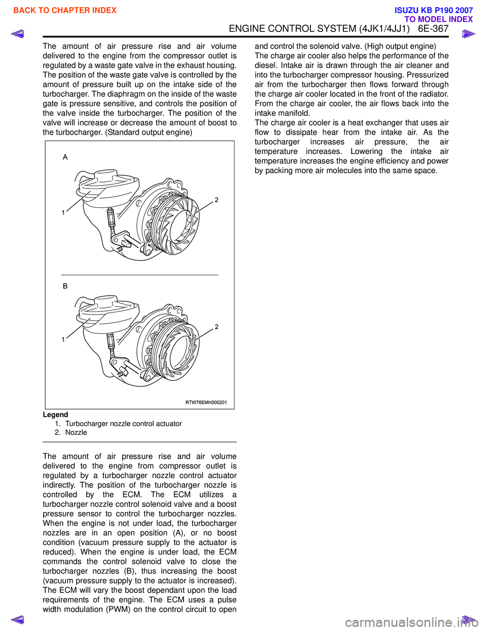
Legend
1. Turbocharger nozzle control actuator
2. Nozzle
The amount of air pressure rise and air volume
delivered to the engine from compressor outlet is
regulated by a turbocharger nozzle control actuator
indirectly. The position of the turbocharger nozzle is
controlled by the ECM. The ECM utilizes a
turbocharger nozzle control solenoid valve and a boost
pressure sensor to control the turbocharger nozzles.
When the engine is not under load, the turbocharger
nozzles are in an open position (A), or no boost
condition (vacuum pressure supply to the actuator is
reduced). When the engine is under load, the ECM
commands the control solenoid valve to close the
turbocharger nozzles (B), thus increasing the boost
(vacuum pressure supply to the actuator is increased).
The ECM will vary the boost dependant upon the load
requirements of the engine. The ECM uses a pulse
width modulation (PWM) on the control circuit to open and control the solenoid valve. (High output engine)
The charge air cooler also helps the performance of the
diesel. Intake air is drawn through the air cleaner and
into the turbocharger compressor housing. Pressurized
air from the turbocharger then flows forward through
the charge air cooler located in the front of the radiator.
From the charge air cooler, the air flows back into the
intake manifold.
The charge air cooler is a heat exchanger that uses air
flow to dissipate hear from the intake air. As the
turbocharger increases air pressure, the air
temperature increases. Lowering the intake air
temperature increases the engine efficiency and power
by packing more air molecules into the same space.
RTW76EMH000201
A
B
1
2
1
2
BACK TO CHAPTER INDEX
TO MODEL INDEX
ISUZU KB P190 2007
Page 1985 of 6020
6E-368 ENGINE CONTROL SYSTEM (4JK1/4JJ1)
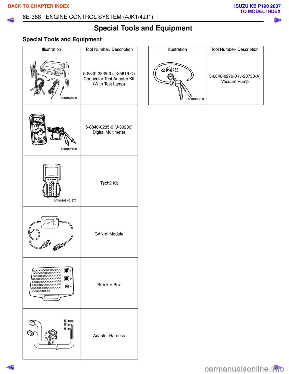
Special Tools and Equipment
Special Tools and Equipment
IllustrationTool Number/ Description
5-8840-2835-0 (J-35616-C) Connector Test Adapter Kit (With Test Lamp)
5-8840-0285-0 (J-39200) Digital Multimeter
Te c h 2 K i t
CAN-di Module Breaker Box
Adapter Harness
5884028350
5884002850
AAW0Z0SH015701
1851110030
A
B C
ABC
5-8840-0279-0 (J-23738-A) Vacuum Pump
Illustration Tool Number/ Description
BACK TO CHAPTER INDEX
TO MODEL INDEX
ISUZU KB P190 2007
Page 1986 of 6020
EXHAUST SYSTEM (4JK1/4JJ1) 6F-1
SECTION 6F
EXHAUST SYSTEM
CONTENTS
Exhaust Silencer and Exhaust Pipe ................... 6F-2
Main Data and Specifications .......................... 6F-2
Components .................................................... 6F-3
Removal .......................................................... 6F-4
Installation ....................................................... 6F-4
Inspection and Repair ..................................... 6F-5
Torque Specifications...................................... 6F-6
EGR Cooler ........................................................ 6F-7 Components (Standard Output) ...................... 6F-7
Components (High Output) ............................. 6F-8
Removal .......................................................... 6F-9
Installation (Standard Output) ......................... 6F-9
Installation (High Output)................................. 6F-10
Torque Specifications (Standard Output) ........ 6F-11
Torque Specifications (High Output) ............... 6F-12
BACK TO CHAPTER INDEX
TO MODEL INDEX
ISUZU KB P190 2007
Page 1987 of 6020
6F-2 EXHAUST SYSTEM (4JK1/4JJ1)
Exhaust Silencer and Exhaust Pipe
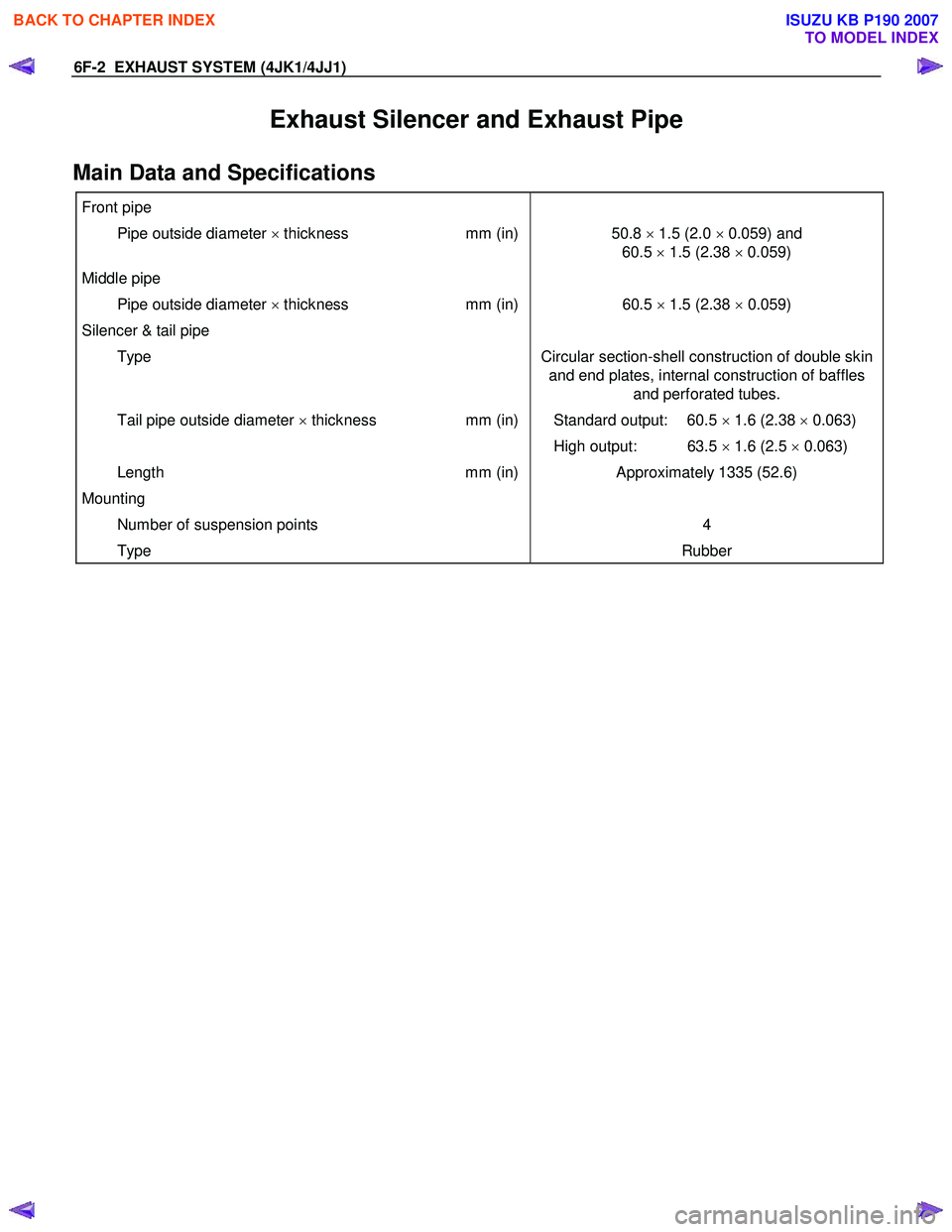
Main Data and Specifications
Front pipe
Pipe outside diameter × thickness mm (in)50.8 × 1.5 (2.0 × 0.059) and
60.5 × 1.5 (2.38 × 0.059)
Middle pipe
Pipe outside diameter × thickness mm (in)60.5 × 1.5 (2.38 × 0.059)
Silencer & tail pipe
Type Circular section-shell construction of double skin
and end plates, internal construction of baffles and perforated tubes.
Tail pipe outside diameter × thickness mm (in) Standard output: 60.5 × 1.6 (2.38 × 0.063)
High output: 63.5 × 1.6 (2.5 × 0.063)
Length mm (in)Approximately 1335 (52.6)
Mounting
Number of suspension points 4
Type Rubber
BACK TO CHAPTER INDEX
TO MODEL INDEX
ISUZU KB P190 2007
Page 1988 of 6020
EXHAUST SYSTEM (4JK1/4JJ1) 6F-3
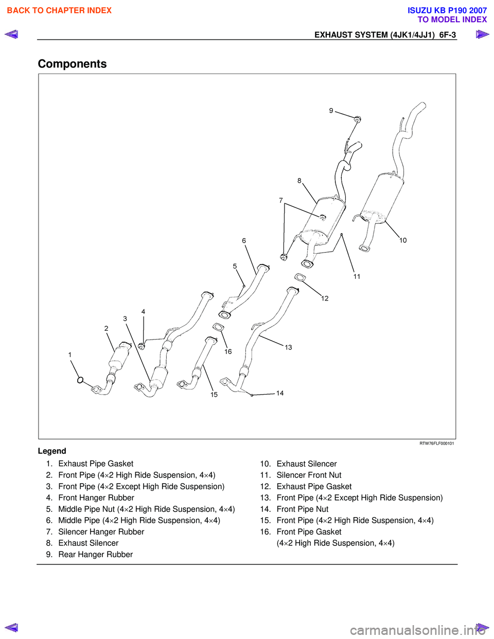
Components
RTW 76FLF000101
Legend
1. Exhaust Pipe Gasket
2. Front Pipe (4 ×2 High Ride Suspension, 4 ×4)
3. Front Pipe (4 ×2 Except High Ride Suspension)
4. Front Hanger Rubber
5. Middle Pipe Nut (4 ×2 High Ride Suspension, 4 ×4)
6. Middle Pipe (4 ×2 High Ride Suspension, 4 ×4)
7. Silencer Hanger Rubber
8. Exhaust Silencer
9. Rear Hanger Rubber
10. Exhaust Silencer
11. Silencer Front Nut
12. Exhaust Pipe Gasket
13. Front Pipe (4 ×2 Except High Ride Suspension)
14. Front Pipe Nut
15. Front Pipe (4 ×2 High Ride Suspension, 4 ×4)
16. Front Pipe Gasket
(4 ×2 High Ride Suspension, 4 ×4)
BACK TO CHAPTER INDEX
TO MODEL INDEX
ISUZU KB P190 2007
Page 1989 of 6020
6F-4 EXHAUST SYSTEM (4JK1/4JJ1)
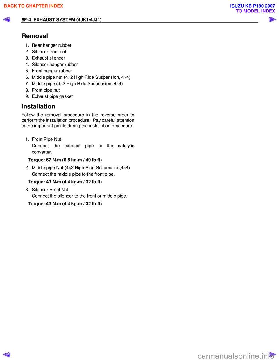
Removal
1. Rear hanger rubber
2. Silencer front nut
3. Exhaust silencer
4. Silencer hanger rubber
5. Front hanger rubber
6. Middle pipe nut (4 ×2 High Ride Suspension, 4 ×4)
7. Middle pipe (4 ×2 High Ride Suspension, 4 ×4)
8. Front pipe nut
9. Exhaust pipe gasket
Installation
Follow the removal procedure in the reverse order to
perform the installation procedure. Pay careful attention
to the important points during the installation procedure.
1. Front Pipe Nut
Connect the exhaust pipe to the catalytic converter.
Torque: 67 N ⋅
⋅⋅
⋅
m (6.8 kg ⋅
⋅⋅
⋅
m / 49 lb ft)
2. Middle pipe Nut (4 ×2 High Ride Suspension,4 ×4)
Connect the middle pipe to the front pipe.
Torque: 43 N ⋅
⋅⋅
⋅
m (4.4 kg ⋅
⋅⋅
⋅
m / 32 lb ft)
3. Silencer Front Nut
Connect the silencer to the front or middle pipe.
Torque: 43 N ⋅
⋅⋅
⋅
m (4.4 kg ⋅
⋅⋅
⋅
m / 32 lb ft)
BACK TO CHAPTER INDEX
TO MODEL INDEX
ISUZU KB P190 2007
Page 1990 of 6020
EXHAUST SYSTEM (4JK1/4JJ1) 6F-5
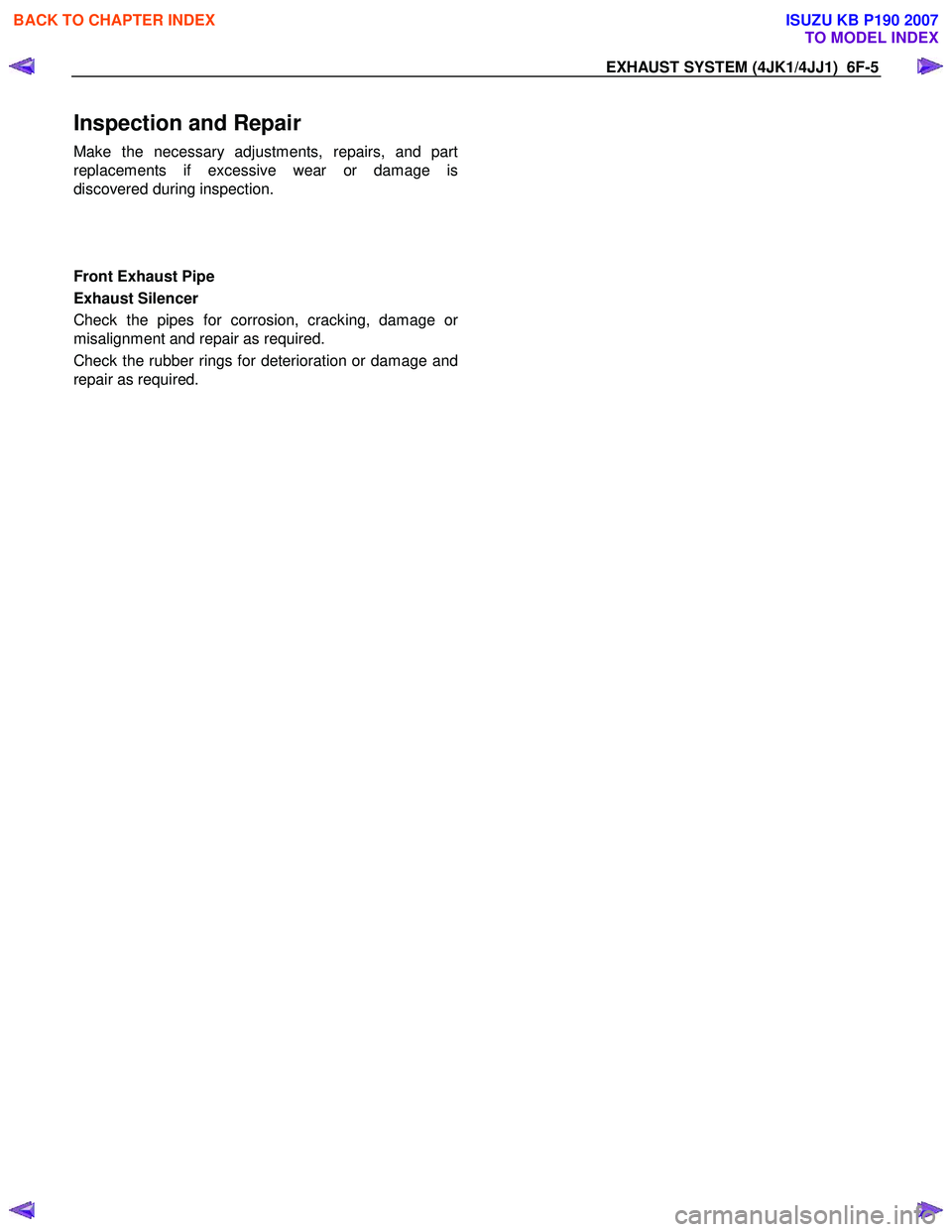
Inspection and Repair
Make the necessary adjustments, repairs, and part
replacements if excessive wear or damage is
discovered during inspection.
Front Exhaust Pipe
Exhaust Silencer
Check the pipes for corrosion, cracking, damage o
r
misalignment and repair as required.
Check the rubber rings for deterioration or damage and
repair as required.
BACK TO CHAPTER INDEX
TO MODEL INDEX
ISUZU KB P190 2007