remote control ISUZU KB P190 2007 Workshop User Guide
[x] Cancel search | Manufacturer: ISUZU, Model Year: 2007, Model line: KB P190, Model: ISUZU KB P190 2007Pages: 6020, PDF Size: 70.23 MB
Page 3259 of 6020
Engine Management – V6 – General Information Page 6C1-1–17
3.9 Serial Data Communication System
The engine control module (ECM) communicates directly with the following control units using the General Motors local
area network (GM LAN) serial data communication protocol:
• Transmission control module (TCM) (if fitted)
• Powertrain interface module (PIM)
The immobiliser control unit (ICU) communicates directly with the PIM using Keyword 2000 serial data communication
protocol. Refer to 11A Immobiliser for further information
As the GM LAN serial data communication protocol is not compatible with the Keyword 2000 serial data communication
protocol, a powertrain interface module (PIM) is integrated to the serial data communication system to perform the
following tasks (Refer to 6E1 Powertrain Interface Module – V6):
• Translate the GM LAN serial data transmitted by the ECM into a Keyword 2000 serial data that can be received
and recognised by the ICU.
• Translate the cruise control switch, automatic transmission power mode switch and 3
rd start switch signal into a GM
LAN serial data that can be received and recognised by the ECM.
3.10 Self Diagnostics System
The ECM constantly performs self-diagnostic tests on the engine management system. W hen the ECM detects a
malfunction, it also stores a diagnostic trouble code (DTC). A stored DTC will identify the problem area(s) and is
designed to assist the technician in rectifying the fault. In addition, DTCs are classified as either Current or History DTC.
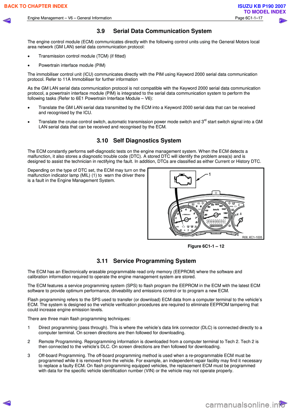
Depending on the type of DTC set, the ECM may turn on the
malfunction indicator lamp (MIL) (1) to warn the driver there
is a fault in the Engine Management System.
Figure 6C1-1 – 12
3.11 Service Programming System
The ECM has an Electronically erasable programmable read only memory (EEPROM) where the software and
calibration information required to operate the engine management system are stored.
The ECM features a service programming system (SPS) to flash program the EEPROM in the ECM with the latest ECM
software to provide optimum performance, driveability and emissions control or to program a new ECM.
Flash programming refers to the SPS used to transfer (or download) ECM data from a computer terminal to the vehicle’s
ECM. The system is designed so the vehicle verification procedures are required to eliminate EEPROM tampering that
could increase engine emission levels.
There are three main flash programming techniques:
1 Direct programming (pass through). This is where the vehicle’s data link connector (DLC) is connected directly to a computer terminal. On screen directions are then followed for downloading.
2 Remote Programming. Reprogramming information is downloaded from a computer terminal to Tech 2. Tech 2 is then connected to the vehicle’s DLC. On screen directions are then followed for downloading.
3 Off-board Programming. The off-board programming method is used when a re-programmable ECM must be programmed while it is removed from the vehicle. For example, an independent repair facility may find it necessary
to replace a faulty ECM. On flash programming equipped vehicles, the replacement ECM must be programmed
with data for the specific vehicle identification number (VIN) or the vehicle may not operate properly.
BACK TO CHAPTER INDEX
TO MODEL INDEX
ISUZU KB P190 2007
Page 3523 of 6020
Engine Management – V6 – Diagnostics Page 6C1-2–245
Starter Motor Relay Test
The engine will crank and start during the
starter relay test.
Allows the Technician to turn the starter relay ‘On’, thereby activating the starter motor and cranking the engine.
Preconditions: Apply park brake, firmly apply foot brake, ignition ‘On’, engine ‘Off’, transmission in Park or Neutral.
Fuel Injector Balance
This test allows the Technician to check the fuel flow through each injector when the engine is not running. The
sequence of events are:
1 Install a fuel pressure gauge to the fuel rail.
2 Select ‘Fuel Injector Balance Test’, from the ‘Actuator Test’ menu on Tech 2
3 Activate the fuel injector balance test with Tech 2. This action activates the fuel pump and stabilises the fuel delivery system fuel pressure. The fuel pump is then turned off.
4 Note the stabilised fuel rail pressure.
5 W hen the pump is turned ‘Off’, the injector is activated for a pre-determined time.
6 The fuel pressure drop is then noted from the fuel pressure gauge.
NOTE
For a detailed procedure and analysis of fuel
injector condition, refer to 5.3 Fuel Injector
Balance Test.
8.7 Programming
F0: ICU Link to ECM/PIM : Should the ECM, PIM or ICU be replaced, the modules must be security linked to
each other. If this linking procedure is not performed, the vehicle will not crank nor run. For additional
information relating to Tech 2 and the linking procedure, refer to 11A – Immobiliser.
NOTE
After an ECU reset, the ignition switch must be
turned Off for at least 10 seconds and then
turned On for at least one minute, before
attempting communication between Tech 2 and
the ECU.
Preconditions: TIS approval (TIS 2000 Security Access) must be obtained, the four digit security number
entered into Tech 2 and the theft deterrent system disarmed. Then the ignition must be turned ‘On’, using a
programmed remote coded key.
F1: Reset ECU : This function erases the security link between the Engine Control Module (ECM) and the
Powertrain Interface Modules (PIM). If this procedure is performed, the engine will not crank nor run. A ICU
Link to ECM/PIM procedure will need to be performed. For additional information relating to the ICU Link to
ECM/PIM procedure, refer to 11A – Immobiliser.
BACK TO CHAPTER INDEX
TO MODEL INDEX
ISUZU KB P190 2007
Page 3524 of 6020
Engine Management – V6 – Diagnostics Page 6C1-2–246
NOTE
After an ECU reset, the ignition switch must be
turned Off for at least 10 seconds and then
turned On for at least one minute, before
attempting communication between Tech 2 and
the ECU.
Preconditions: The four digit security code must be entered into Tech 2 and the theft deterrent system
must be disarmed and the ignition switched ‘On’ with a programmed remote coded key.
F2: Fuel Trim Reset : This function resets the fuel trim data values learned by the ECM.
F3: Throttle Body Relearn : In this mode, Tech 2 commands the throttle plate from its rest position to full closed
then to about 10% open. This procedure takes approximately 6 – 8 seconds. At the start of this procedure,
the Tech 2, ‘Electronic Throttle Control Learn Counter’ parameter should display ‘0’ then count up to 11, after
the procedure is completed. If the counter does not start at ‘0’, nor display a count of ‘11’ at the conclusion of
the procedure, a fault has occurred and a DTC will set.
BACK TO CHAPTER INDEX
TO MODEL INDEX
ISUZU KB P190 2007
Page 3744 of 6020
Powertrain Interface Module – V6 Page 6E1–83
13.5 Security
F0: Immobiliser Link To ECM/PIM
Should the ECM, PIM or ICU be replaced, the modules must be security linked to each other. If this linking
procedure is not performed, the vehicle will not crank nor run. For additional information relating to Tech 2
and the linking procedure, refer to 11A – Immobiliser.
NOTE
After an ECU reset, the ignition switch must be
turned Off for at least 10 seconds and then
turned On for at least one minute, before
attempting communication between Tech 2 and
the ECU.
Preconditions: TIS approval (TIS 2000 Security Access) must be obtained, the four digit security number
entered into Tech 2 and the theft deterrent system disarmed. Then the ignition must be turned ‘On’, using a
programmed remote coded key.
F1: Reset PIM
This function erases the security link between the Engine Control Module (ECM) and the Powertrain Interface Modules (PIM). If this procedure is performed, the engine will not crank nor run. A ICU Link to ECM/PIM
procedure will need to be performed. For additional information relating to the ICU Link to ECM/PIM
procedure, refer to 11A – Immobiliser.
NOTE
After an ECU reset, the ignition switch must be
turned Off for at least 10 seconds and then
turned On for at least one minute, before
attempting communication between Tech 2 and
the ECU.
Preconditions: The four digit security code must be entered into Tech 2 and the ignition switched ‘On’ with a
programmed remote coded key.
F2: Security Information
The security code is required when performing certain PIM, ICU and ECM programming functions. W hen Tech 2 requests the security code to be entered, and an incorrect code is entered, the PIM will go into a
security wait time stage. This wait time stage will prevent any further attempts to enter the security code until
the wait time has elapsed.
Should a second incorrect security code be entered after the initial wait time has elapsed, the PIM will go into a second wait time stage. The wait time will increase each time an incorrect code is entered. W hen the
correct code is entered the wait time will reset back to its original value of 10 seconds.
NOTE
The ignition switch must be in the ON position
with the battery connected during the wait time
period.
The wait time stages are as follows: • Stage 1 = 10 seconds.
• Stage 2 = 10 seconds.
• Stage 3 = 10 minutes.
• Stage 4 = 20 minutes.
• Stage 5 = 40 minutes.
• Stage 5 = 80 minutes.
BACK TO CHAPTER INDEX
TO MODEL INDEX
ISUZU KB P190 2007
Page 4285 of 6020
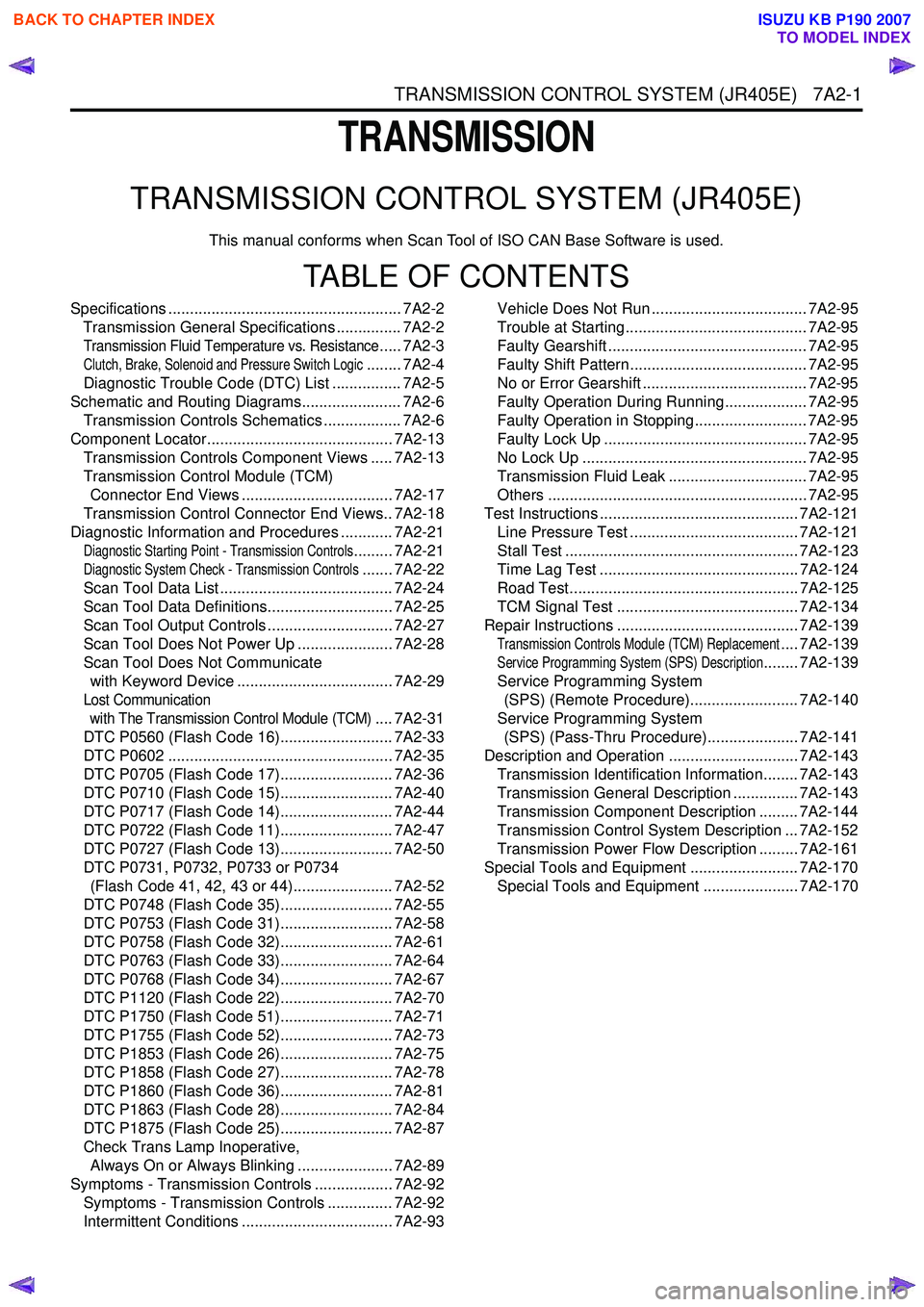
TRANSMISSION CONTROL SYSTEM (JR405E) 7A2-1
TRANSMISSION
TRANSMISSION CONTROL SYSTEM (JR405E)
This manual conforms when Scan Tool of ISO CAN Base Software is used.
TABLE OF CONTENTS
Specifications ...................................................... 7A2-2Transmission General Specifications ............... 7A2-2
Transmission Fluid Temperature vs. Resistance..... 7A2-3
Clutch, Brake, Solenoid and Pressure Switch Logic........ 7A2-4
Diagnostic Trouble Code (DTC) List ................ 7A2-5
Schematic and Routing Diagrams....................... 7A2-6 Transmission Controls Schematics .................. 7A2-6
Component Locator........................................... 7A2-13 Transmission Controls Component Views ..... 7A2-13
Transmission Control Module (TCM) Connector End Views ................................... 7A2-17
Transmission Control Connector End Views.. 7A2-18
Diagnostic Information and Procedures ............ 7A2-21
Diagnostic Starting Point - Transmission Controls......... 7A2-21
Diagnostic System Check - Transmission Controls....... 7A2-22
Scan Tool Data List ........................................ 7A2-24
Scan Tool Data Definitions............................. 7A2-25
Scan Tool Output Controls ............................. 7A2-27
Scan Tool Does Not Power Up ...................... 7A2-28
Scan Tool Does Not Communicate with Keyword Device .................................... 7A2-29
Lost Communication with The Transmission Control Module (TCM)
.... 7A2-31
DTC P0560 (Flash Code 16).......................... 7A2-33
DTC P0602 .................................................... 7A2-35
DTC P0705 (Flash Code 17).......................... 7A2-36
DTC P0710 (Flash Code 15).......................... 7A2-40
DTC P0717 (Flash Code 14).......................... 7A2-44
DTC P0722 (Flash Code 11).......................... 7A2-47
DTC P0727 (Flash Code 13).......................... 7A2-50
DTC P0731, P0732, P0733 or P0734 (Flash Code 41, 42, 43 or 44)....................... 7A2-52
DTC P0748 (Flash Code 35).......................... 7A2-55
DTC P0753 (Flash Code 31).......................... 7A2-58
DTC P0758 (Flash Code 32).......................... 7A2-61
DTC P0763 (Flash Code 33).......................... 7A2-64
DTC P0768 (Flash Code 34).......................... 7A2-67
DTC P1120 (Flash Code 22).......................... 7A2-70
DTC P1750 (Flash Code 51).......................... 7A2-71
DTC P1755 (Flash Code 52).......................... 7A2-73
DTC P1853 (Flash Code 26).......................... 7A2-75
DTC P1858 (Flash Code 27).......................... 7A2-78
DTC P1860 (Flash Code 36).......................... 7A2-81
DTC P1863 (Flash Code 28).......................... 7A2-84
DTC P1875 (Flash Code 25).......................... 7A2-87
Check Trans Lamp Inoperative, Always On or Always Blinking ...................... 7A2-89
Symptoms - Transmission Controls .................. 7A2-92 Symptoms - Transmission Controls ............... 7A2-92
Intermittent Conditions ................................... 7A2-93 Vehicle Does Not Run .................................... 7A2-95
Trouble at Starting.......................................... 7A2-95
Faulty Gearshift .............................................. 7A2-95
Faulty Shift Pattern......................................... 7A2-95
No or Error Gearshift ...................................... 7A2-95
Faulty Operation During Running................... 7A2-95
Faulty Operation in Stopping.......................... 7A2-95
Faulty Lock Up ............................................... 7A2-95
No Lock Up .................................................... 7A2-95
Transmission Fluid Leak ................................ 7A2-95
Others ............................................................ 7A2-95
Test Instructions .............................................. 7A2-121 Line Pressure Test ....................................... 7A2-121
Stall Test ...................................................... 7A2-123
Time Lag Test .............................................. 7A2-124
Road Test..................................................... 7A2-125
TCM Signal Test .......................................... 7A2-134
Repair Instructions .......................................... 7A2-139
Transmission Controls Module (TCM) Replacement.... 7A2-139
Service Programming System (SPS) Description........ 7A2-139
Service Programming System (SPS) (Remote Procedure)......................... 7A2-140
Service Programming System (SPS) (Pass-Thru Procedure)..................... 7A2-141
Description and Operation .............................. 7A2-143 Transmission Identification Information........ 7A2-143
Transmission General Description ............... 7A2-143
Transmission Component Description ......... 7A2-144
Transmission Control System Description ... 7A2-152
Transmission Power Flow Description ......... 7A2-161
Special Tools and Equipment ......................... 7A2-170 Special Tools and Equipment ...................... 7A2-170
BACK TO CHAPTER INDEX
TO MODEL INDEX
ISUZU KB P190 2007
Page 4378 of 6020
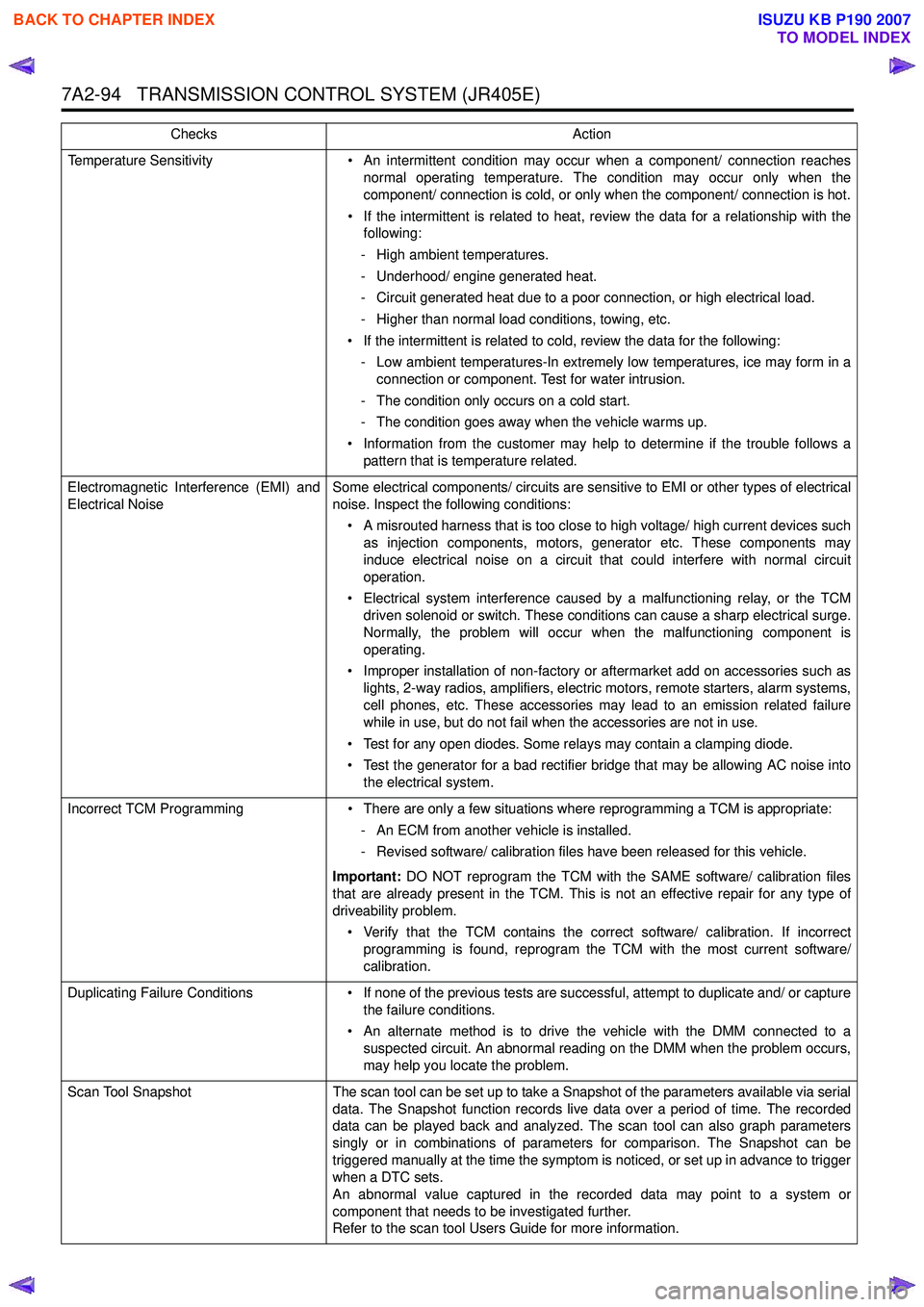
7A2-94 TRANSMISSION CONTROL SYSTEM (JR405E)
Temperature Sensitivity• An intermittent condition may occur when a component/ connection reaches
normal operating temperature. The condition may occur only when the
component/ connection is cold, or only when the component/ connection is hot.
• If the intermittent is related to heat, review the data for a relationship with the following:
- High ambient temperatures.
- Underhood/ engine generated heat.
- Circuit generated heat due to a poor connection, or high electrical load.
- Higher than normal load conditions, towing, etc.
• If the intermittent is related to cold, review the data for the following: - Low ambient temperatures-In extremely low temperatures, ice may form in a connection or component. Test for water intrusion.
- The condition only occurs on a cold start.
- The condition goes away when the vehicle warms up.
• Information from the customer may help to determine if the trouble follows a pattern that is temperature related.
Electromagnetic Interference (EMI) and
Electrical Noise Some electrical components/ circuits are sensitive to EMI or other types of electrical
noise. Inspect the following conditions:
• A misrouted harness that is too close to high voltage/ high current devices such as injection components, motors, generator etc. These components may
induce electrical noise on a circuit that could interfere with normal circuit
operation.
• Electrical system interference caused by a malfunctioning relay, or the TCM driven solenoid or switch. These conditions can cause a sharp electrical surge.
Normally, the problem will occur when the malfunctioning component is
operating.
• Improper installation of non-factory or aftermarket add on accessories such as lights, 2-way radios, amplifiers, electric motors, remote starters, alarm systems,
cell phones, etc. These accessories may lead to an emission related failure
while in use, but do not fail when the accessories are not in use.
• Test for any open diodes. Some relays may contain a clamping diode.
• Test the generator for a bad rectifier bridge that may be allowing AC noise into the electrical system.
Incorrect TCM Programming • There are only a few situations where reprogramming a TCM is appropriate:
- An ECM from another vehicle is installed.
- Revised software/ calibration files have been released for this vehicle.
Important: DO NOT reprogram the TCM with the SAME software/ calibration files
that are already present in the TCM. This is not an effective repair for any type of
driveability problem.
• Verify that the TCM contains the correct software/ calibration. If incorrect programming is found, reprogram the TCM with the most current software/
calibration.
Duplicating Failure Conditions • If none of the previous tests are successful, attempt to duplicate and/ or capture
the failure conditions.
• An alternate method is to drive the vehicle with the DMM connected to a suspected circuit. An abnormal reading on the DMM when the problem occurs,
may help you locate the problem.
Scan Tool Snapshot The scan tool can be set up to take a Snapshot of the parameters available via serial
data. The Snapshot function records live data over a period of time. The recorded
data can be played back and analyzed. The scan tool can also graph parameters
singly or in combinations of parameters for comparison. The Snapshot can be
triggered manually at the time the symptom is noticed, or set up in advance to trigger
when a DTC sets.
An abnormal value captured in the recorded data may point to a system or
component that needs to be investigated further.
Refer to the scan tool Users Guide for more information.
Checks
Action
BACK TO CHAPTER INDEX
TO MODEL INDEX
ISUZU KB P190 2007
Page 4423 of 6020

TRANSMISSION CONTROL SYSTEM (JR405E) 7A2-139
Repair Instructions
Transmission Controls Module (TCM) Replacement
Description
The following A - C steps provide an overview
procedure to replace and reprogram a TCM. Each A -C
steps is explained further in this section.
A. Replace the old TCM with the new TCM.
B. Program the latest software and calibrations into the
new TCM using the Service Programming System
(SPS) if released. If not released, do not perform this
and skip to Step C.
C. Program the vehicle identification number (VIN) into
the TCM.
A. Removal and Installation
Removal Procedure 1. Disconnect the negative battery cable.
2. Disconnect the TCM harness connectors (1).
3. Loosen nuts (2) and remove the TCM (3) from the bracket (4).
Installation Procedure
Follow the removal steps in the reverse order. Be sure
that the connectors are securely fastened.
B. Programming Software and Calibrations
Program the latest software/ calibrations if released.
Refer to Service Programming System (SPS)
Description and SPS (Remote Procedure) or SPS
(Pass-Thru Procedure) in this section. If not released,
do not perform this and skip to Step C.
C. Programming Vehicle Identification Number
(VIN) Notice:
If you have performed SPS in the previous
step, VIN has prgrommaned already. Programming VIN
is not necessary in this step.
1. Install a scan tool.
2. Turn ON the ignition, with the engine OFF.
3. Select Diagnostics > appropriate vehicle identification > AT JR405E > Programming >
Program VIN.
4. If you installed a new, skip to step 8. If you installed a reused TCM from another vehicle or incorrect
VIN is programmed before, the TCM might be
locked already. In order to get programming
approval, the on-screen displays a message to
user. Get programming approval from the TIS
2000 using the following procedure:
a. Connect a scan tool to the terminal that installed TIS 2000 with the latest software and
the hardware key is plugged into port.
b. Turn ON the scan tool and keep at title screen.
c. Launch the TIS application.
d. Select the Security Access at the main screen.
e. Highlight the “Tech 2" on the Diagnostic Tool Selection screen and click “Next”.
f. Click “Close” on the Security Access Enabled screen.
g. Turn OFF the scan tool.
h. Disconnect the scan tool from the terminal.
5. Install a scan tool to the vehicle.
6. Turn ON the ignition, with the engine OFF.
7. Select Diagnostics > appropriate vehicle identification > AT JR405E > Programming >
Program VIN.
8. Input 17 digits of correct VIN.
9. After complete the programming, turn OFF/ ON the ignition.
10. Select Diagnostics > Lock ECU.
11. Follow the on-screen instructions and turn OFF/ ON the ignition.
Service Programming System (SPS)
Description
The service programming system (SPS) allows a
technician to program a control module through the
data link connector (DLC). The information transfer
circuit that is used at the DLC is the same serial data
circuit used by the scan tool for retrieving DTCs,
displaying data, clearing DTCs etc. This procedure
offers the ability to install software/ calibrations
matched to a particular vehicle.
Most control modules have two types of memory. The
software/ calibrations reside in the flash memory. The
two types of memory are listed below:
1
3 42
BACK TO CHAPTER INDEX
TO MODEL INDEX
ISUZU KB P190 2007
Page 4424 of 6020
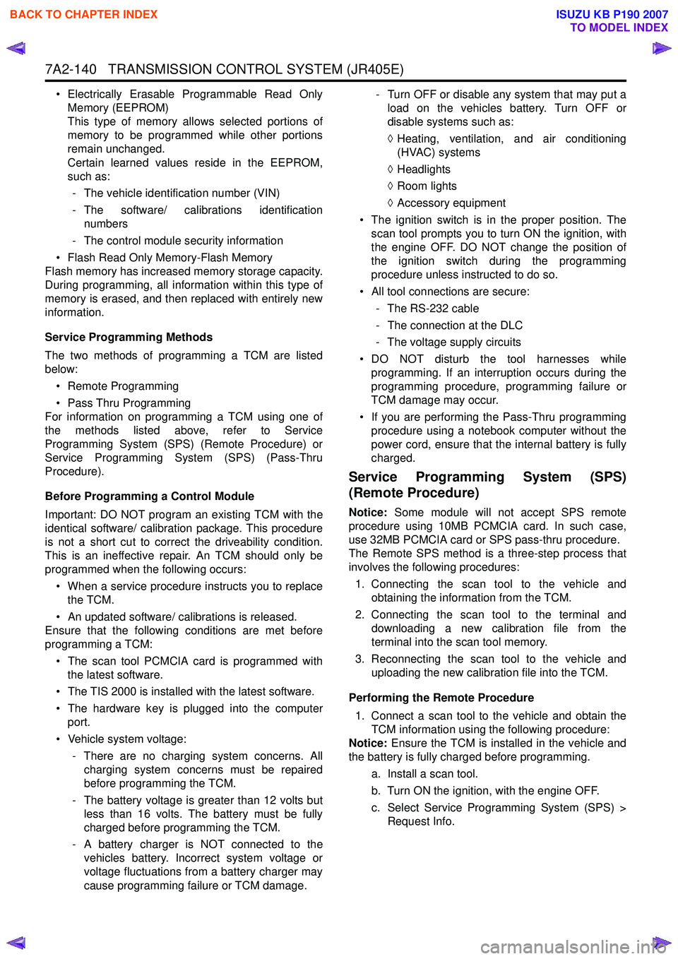
7A2-140 TRANSMISSION CONTROL SYSTEM (JR405E)
• Electrically Erasable Programmable Read OnlyMemory (EEPROM)
This type of memory allows selected portions of
memory to be programmed while other portions
remain unchanged.
Certain learned values reside in the EEPROM,
such as:
- The vehicle identification number (VIN)
- The software/ calibrations identification numbers
- The control module security information
• Flash Read Only Memory-Flash Memory
Flash memory has increased memory storage capacity.
During programming, all information within this type of
memory is erased, and then replaced with entirely new
information.
Service Programming Methods
The two methods of programming a TCM are listed
below:
• Remote Programming
• Pass Thru Programming
For information on programming a TCM using one of
the methods listed above, refer to Service
Programming System (SPS) (Remote Procedure) or
Service Programming System (SPS) (Pass-Thru
Procedure).
Before Programming a Control Module
Important: DO NOT program an existing TCM with the
identical software/ calibration package. This procedure
is not a short cut to correct the driveability condition.
This is an ineffective repair. An TCM should only be
programmed when the following occurs:
• When a service procedure instructs you to replace the TCM.
• An updated software/ calibrations is released.
Ensure that the following conditions are met before
programming a TCM:
• The scan tool PCMCIA card is programmed with the latest software.
• The TIS 2000 is installed with the latest software.
• The hardware key is plugged into the computer port.
• Vehicle system voltage:
- There are no charging system concerns. Allcharging system concerns must be repaired
before programming the TCM.
- The battery voltage is greater than 12 volts but less than 16 volts. The battery must be fully
charged before programming the TCM.
- A battery charger is NOT connected to the vehicles battery. Incorrect system voltage or
voltage fluctuations from a battery charger may
cause programming failure or TCM damage. - Turn OFF or disable any system that may put a
load on the vehicles battery. Turn OFF or
disable systems such as:
◊ Heating, ventilation, and air conditioning
(HVAC) systems
◊ Headlights
◊ Room lights
◊ Accessory equipment
• The ignition switch is in the proper position. The scan tool prompts you to turn ON the ignition, with
the engine OFF. DO NOT change the position of
the ignition switch during the programming
procedure unless instructed to do so.
• All tool connections are secure:
- The RS-232 cable
- The connection at the DLC
- The voltage supply circuits
• DO NOT disturb the tool harnesses while programming. If an interruption occurs during the
programming procedure, programming failure or
TCM damage may occur.
• If you are performing the Pass-Thru programming procedure using a notebook computer without the
power cord, ensure that the internal battery is fully
charged.
Service Programming System (SPS)
(Remote Procedure)
Notice: Some module will not accept SPS remote
procedure using 10MB PCMCIA card. In such case,
use 32MB PCMCIA card or SPS pass-thru procedure.
The Remote SPS method is a three-step process that
involves the following procedures:
1. Connecting the scan tool to the vehicle and obtaining the information from the TCM.
2. Connecting the scan tool to the terminal and downloading a new calibration file from the
terminal into the scan tool memory.
3. Reconnecting the scan tool to the vehicle and uploading the new calibration file into the TCM.
Performing the Remote Procedure 1. Connect a scan tool to the vehicle and obtain the TCM information using the following procedure:
Notice: Ensure the TCM is installed in the vehicle and
the battery is fully charged before programming.
a. Install a scan tool.
b. Turn ON the ignition, with the engine OFF.
c. Select Service Programming System (SPS) > Request Info.
BACK TO CHAPTER INDEX
TO MODEL INDEX
ISUZU KB P190 2007
Page 4653 of 6020
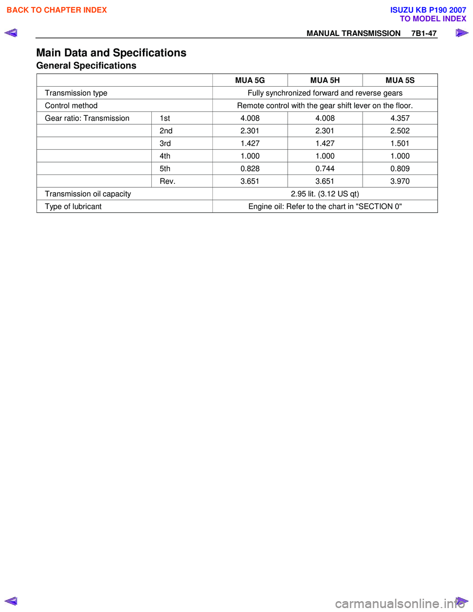
MANUAL TRANSMISSION 7B1-47
Main Data and Specifications
General Specifications
MUA 5G MUA 5H MUA 5S
Transmission type Fully synchronized forward and reverse gears
Control method Remote control with the gear shift lever on the floor.
Gear ratio: Transmission 1st 4.008 4.008 4.357
2nd 2.301 2.301 2.502
3rd 1.427 1.427 1.501
4th 1.000 1.000 1.000
5th 0.828 0.744 0.809
Rev. 3.651 3.651 3.970
Transmission oil capacity 2.95 lit. (3.12 US qt)
Type of lubricant Engine oil: Refer to the chart in "SECTION 0"
BACK TO CHAPTER INDEX
TO MODEL INDEX
ISUZU KB P190 2007
Page 4707 of 6020
MANUAL TRANSMISSION 7B1-101
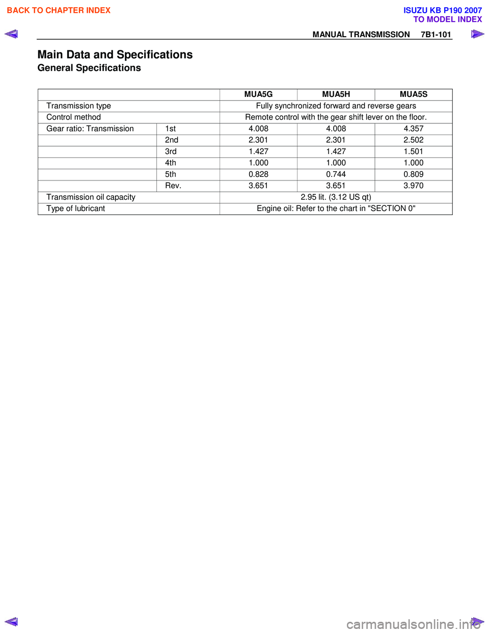
Main Data and Specifications
General Specifications
MUA5G MUA5H MUA5S
Transmission type Fully synchronized forward and reverse gears
Control method Remote control with the gear shift lever on the floor.
Gear ratio: Transmission 1st 4.008 4.008 4.357
2nd 2.301 2.301 2.502
3rd 1.427 1.427 1.501
4th 1.000 1.000 1.000
5th 0.828 0.744 0.809
Rev. 3.651 3.651 3.970
Transmission oil capacity 2.95 lit. (3.12 US qt)
Type of lubricant Engine oil: Refer to the chart in "SECTION 0"
BACK TO CHAPTER INDEX
TO MODEL INDEX
ISUZU KB P190 2007