indicator ISUZU KB P190 2007 Workshop Repair Manual
[x] Cancel search | Manufacturer: ISUZU, Model Year: 2007, Model line: KB P190, Model: ISUZU KB P190 2007Pages: 6020, PDF Size: 70.23 MB
Page 3826 of 6020

Automatic Transmission – 4L60E – Electrical Diagnosis Page 7C2–40
Step Action Yes No
2 1 Connect Tech 2 to the DLC.
2 Turn on the ignition, with the engine off.
NOTE
Before clearing the DTC, use the Tech 2 Freeze
Frame/Failure Record to record the transmission
parameters at the time the DTC set. Using Tech 2 to clear
the DTC(s) erases the Freeze Frame/Failure Record
records from the TCM.
3 On Tech 2 select: Transmission / Automatic Transmission / Diagnostic
Trouble Codes / Freeze Frame.
4 Select the relevant DTC and note the parameters at the time of the DTC setting.
5 On Tech 2 select:
Diagnostic Trouble Codes / Clear Engine & Transmission
DTCs.
6 Follow the instructions on Tech 2 and clear the DTCs.
7 On Tech 2 select: Diagnostic Trouble Codes / Read DTC Information.
Has DTC P0562 set? Refer to
4.10 DTC
P0562 – System
Voltage Low Go to Step 3
3 1 Start the engine.
2 Allow the engine to warm up to normal operating temperature.
Is the alternator fail warning indicator illuminated? Refer to
6D1-1 Charging system – V6 Go to Step 4
4 1 Turn off all electrical accessories.
2 Increase the engine speed to 2,000 r.p.m.
3 Using the multimeter set to measure voltage, probe across the battery terminals. Record the measurement for reference.
Does the multimeter display 12.5 – 14.5 V? Go to Step 5 Refer to
6D1-1 Charging system – V6
5 1 Leave the engine running.
2 On Tech 2 select: Data Display / Transmission Data
and observe the Ignition Voltage on Tech 2.
3 Increase the engine speed to 2,000 r.p.m.
Is the difference between the voltage displayed on Tech 2 and the
voltage measurement in Step 4 greater than 1.0 V? Go to Step 7 Go to Step 6
6 Did DTC P0563 reset?
Go to Step 7 Check for an
intermittent fault in the circuit, refer to
8A Electrical-Body and Chassis
7 Replace the TCM, refer to 7C4 Automatic Transmission – 4L60E –
On-vehicle Servicing.
Is the action complete? Go to Step 8 —
BACK TO CHAPTER INDEX
TO MODEL INDEX
ISUZU KB P190 2007
Page 3918 of 6020

Automatic Transmission – 4L60E – On-vehicle Servicing Page 7C4–5
2 Maintenance Operations
2.1 Transmission Fluid
When adding or changing the transmission fluid, use only the recommended automatic transmission fluid, refer to
0B Maintenance and Lubrication.
For the automatic transmission fluid diagnosis, refer to 7C3 Automatic Transmission – 4L60E – Hydraulic and
Mechanical Diagnosis.
Transmission Fluid Colour
New transmission fluid is red in colour due to a dye that is added to the fluid so it can be distinguished from other oils and
lubricants. The red dye is not permanent and as such, is not an indicator of the quality of the fluid.
As the vehicle is driven the transmission fluid will quickly look darker in colour and appear to be a light brown. A dark
brown colour with a distinctively burnt odour may indicate fluid deterioration and the need for fluid replacement.
NOTE
A dark brown fluid colour observed, coupled with
a reported delayed shift pattern may only indicate
that fluid replacement is required. This is not a
definite indication of a potential transmission
failure.
Transmission Fluid Level
NOTE
Carry out this operation with the transmission at
normal operating temperature (82 – 94°C), as the
temperature greatly affects the fluid level.
1 Drive the vehicle for a distance of at least 25 km to bring the transmission up to normal operating temperature.
If the transmission is not at normal operating
temperature and the correct procedure is not
followed, the result could be a false reading of
the fluid level on the transmission fluid
indicator.
2 If the vehicle has been operated under any of the following conditions, switch the engine off and allow the transmission to cool for approximately thirty minutes:
• in high ambient temperatures above 32° C,
• at sustained high speeds,
• in heavy stop / start city traffic during hot weather, or
• towing.
3 Park the vehicle on level ground.
4 Move the gear selector to the Park position and apply the park brake.
5 Allow the engine to idle for 3 minutes with the accessories turned off.
BACK TO CHAPTER INDEX
TO MODEL INDEX
ISUZU KB P190 2007
Page 3919 of 6020

Automatic Transmission – 4L60E – On-vehicle Servicing Page 7C4–6
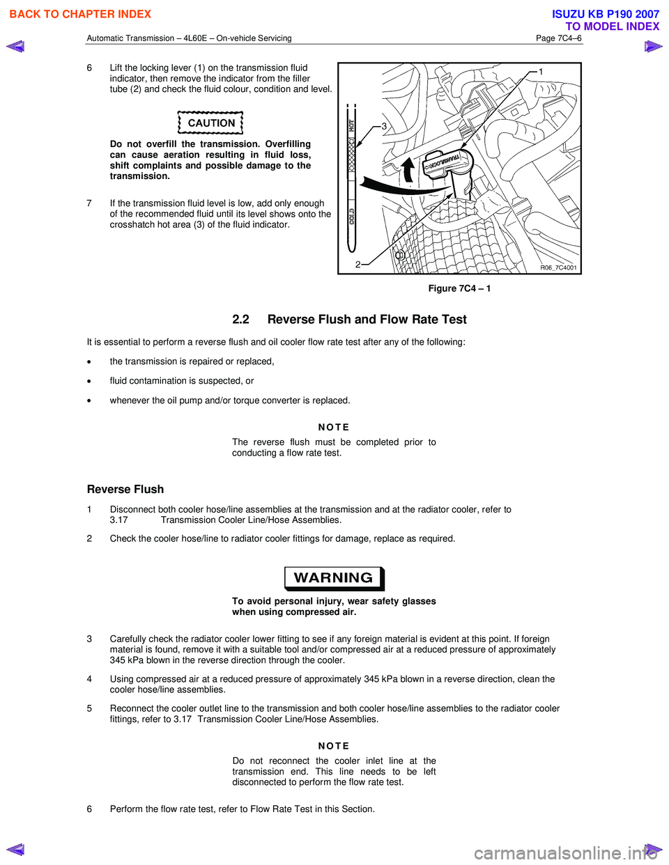
6 Lift the locking lever (1) on the transmission fluid
indicator, then remove the indicator from the filler
tube (2) and check the fluid colour, condition and level.
Do not overfill the transmission. Overfilling
can cause aeration resulting in fluid loss,
shift complaints and possible damage to the
transmission.
7 If the transmission fluid level is low, add only enough of the recommended fluid until
its level shows onto the
crosshatch hot area (3) of the fluid indicator.
Figure 7C4 – 1
2.2 Reverse Flush and Flow Rate Test
It is essential to perform a reverse flush and oil cooler flow rate test after any of the following:
• the transmission is repaired or replaced,
• fluid contamination is suspected, or
• whenever the oil pump and/or torque converter is replaced.
NOTE
The reverse flush must be completed prior to
conducting a flow rate test.
Reverse Flush
1 Disconnect both cooler hose/line assemblies at the transmission and at the radiator cooler, refer to 3.17 Transmission Cooler Line/Hose Assemblies.
2 Check the cooler hose/line to radiator cooler fittings for damage, replace as required.
To avoid personal injury, wear safety glasses
when using compressed air.
3 Carefully check the radiator cooler lower fitting to see if any foreign material is evident at this point. If foreign material is found, remove it with a suitable tool and/or compressed air at a reduced pressure of approximately
345 kPa blown in the reverse direction through the cooler.
4 Using compressed air at a reduced pressure of approximately 345 kPa blown in a reverse direction, clean the cooler hose/line assemblies.
5 Reconnect the cooler outlet line to the transmission and both cooler hose/line assemblies to the radiator cooler fittings, refer to 3.17 Transmission Cooler Line/Hose Assemblies.
NOTE
Do not reconnect the cooler inlet line at the
transmission end. This line needs to be left
disconnected to perform the flow rate test.
6 Perform the flow rate test, refer to Flow Rate Test in this Section.
BACK TO CHAPTER INDEX
TO MODEL INDEX
ISUZU KB P190 2007
Page 3952 of 6020

Automatic Transmission – 4L60E – On-vehicle Servicing Page 7C4–39
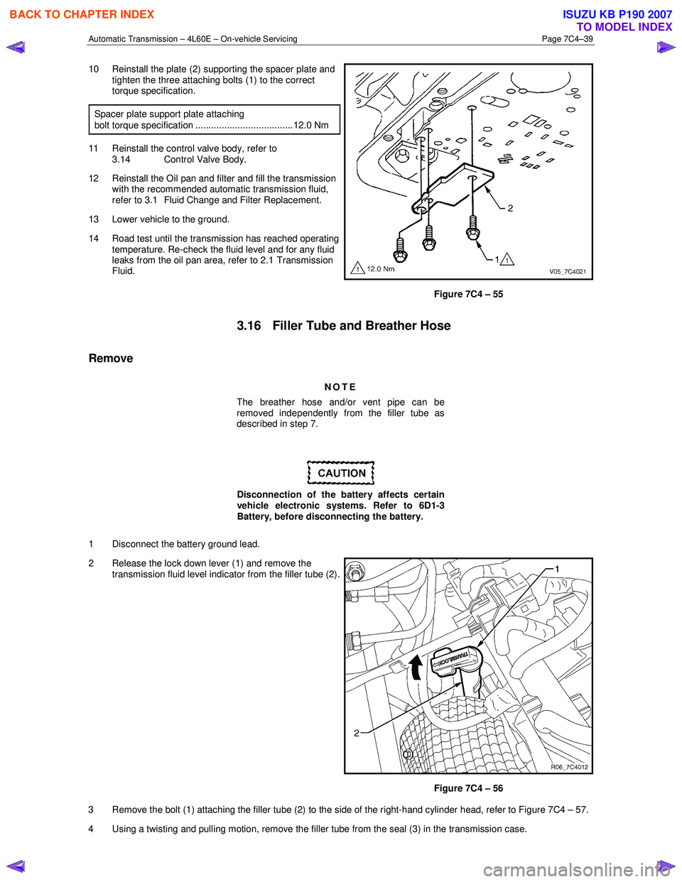
10 Reinstall the plate (2) supporting the spacer plate and
tighten the three attaching bolts (1) to the correct
torque specification.
Spacer plate support plate attaching
bolt torque specification ..................................... 12.0 Nm
11 Reinstall the control valve body, refer to 3.14 Control Valve Body.
12 Reinstall the Oil pan and filter and fill the transmission with the recommended automatic transmission fluid,
refer to 3.1 Fluid Change and Filter Replacement.
13 Lower vehicle to the ground.
14 Road test until the transmission has reached operating temperature. Re-check the fluid level and for any fluid
leaks from the oil pan area, refer to 2.1 Transmission
Fluid.
Figure 7C4 – 55
3.16 Filler Tube and Breather Hose
Remove
NOTE
The breather hose and/or vent pipe can be
removed independently from the filler tube as
described in step 7.
Disconnection of the battery affects certain
vehicle electronic systems. Refer to 6D1-3
Battery, before disconnecting the battery.
1 Disconnect the battery ground lead.
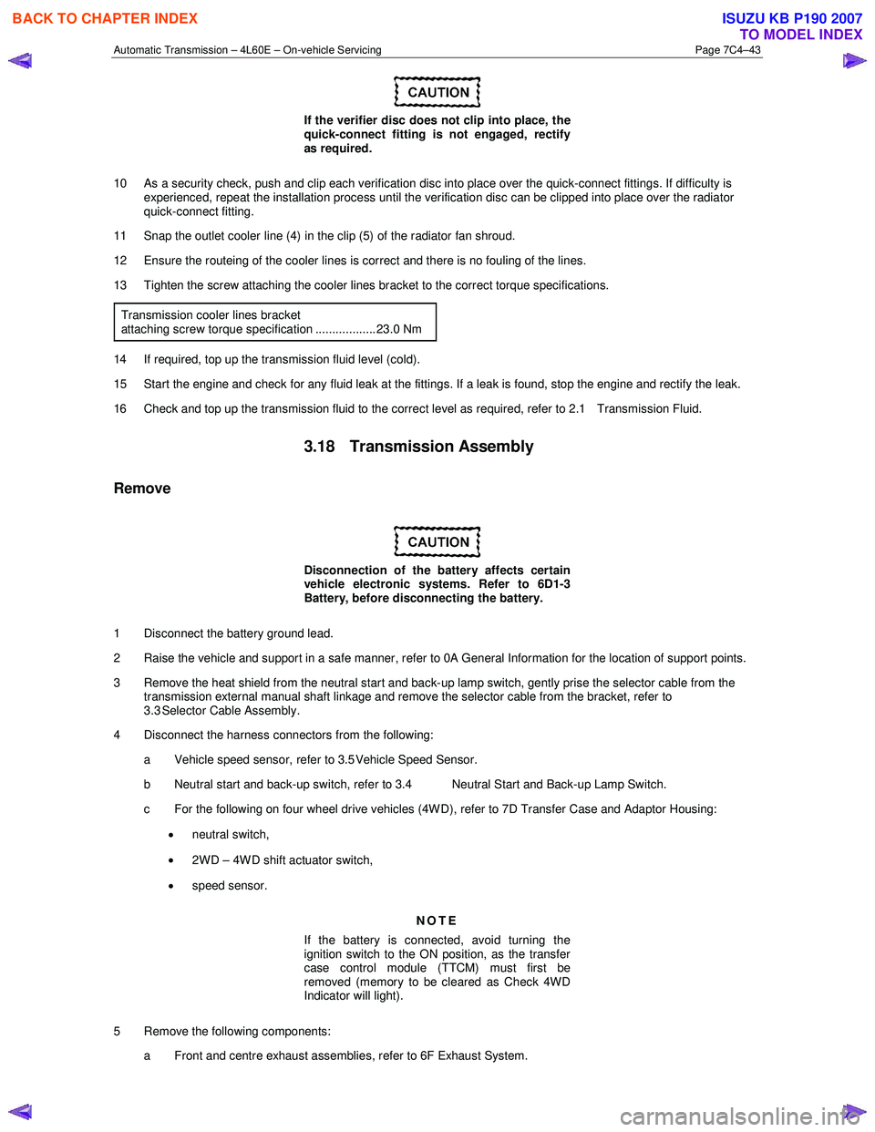
2 Release the lock down lever (1) and remove the transmission fluid level indicator from the filler tube (2).
Figure 7C4 – 56
3 Remove the bolt (1) attaching the filler tube (2) to the side of the right-hand cylinder head, refer to Figure 7C4 – 57.
4 Using a twisting and pulling motion, remove the filler tube from the seal (3) in the transmission case.
BACK TO CHAPTER INDEX
TO MODEL INDEX
ISUZU KB P190 2007
Page 3956 of 6020

Automatic Transmission – 4L60E – On-vehicle Servicing Page 7C4–43
If the verifier disc does not clip into place, the
quick-connect fitting is not engaged, rectify
as required.
10 As a security check, push and clip each verification disc into place over the quick-connect fittings. If difficulty is experienced, repeat the installation process until the verification disc can be clipped into place over the radiator
quick-connect fitting.
11 Snap the outlet cooler line (4) in the clip (5) of the radiator fan shroud.
12 Ensure the routeing of the cooler lines is correct and there is no fouling of the lines.
13 Tighten the screw attaching the cooler lines bracket to the correct torque specifications.
Transmission cooler lines bracket
attaching screw torque specification .................. 23.0 Nm
14 If required, top up the transmission fluid level (cold).
15 Start the engine and check for any fluid leak at the fittings. If a leak is found, stop the engine and rectify the leak.
16 Check and top up the transmission fluid to the correct level as required, refer to 2.1 Transmission Fluid.
3.18 Transmission Assembly
Remove
Disconnection of the battery affects certain
vehicle electronic systems. Refer to 6D1-3
Battery, before disconnecting the battery.
1 Disconnect the battery ground lead.
2 Raise the vehicle and support in a safe manner, refer to 0A General Information for the location of support points.
3 Remove the heat shield from the neutral start and back-up lamp switch, gently prise the selector cable from the transmission external manual shaft linkage and remove the selector cable from the bracket, refer to
3.3 Selector Cable Assembly.
4 Disconnect the harness connectors from the following:
a Vehicle speed sensor, refer to 3.5 Vehicle Speed Sensor.
b Neutral start and back-up switch, refer to 3.4 Neutral Start and Back-up Lamp Switch.
c For the following on four wheel drive vehicles (4W D), refer to 7D Transfer Case and Adaptor Housing:
• neutral switch,
• 2WD – 4WD shift actuator switch,
• speed sensor.
NOTE
If the battery is connected, avoid turning the
ignition switch to the ON position, as the transfer
case control module (TTCM) must first be
removed (memory to be cleared as Check 4W D
Indicator will light).
5 Remove the following components: a Front and centre exhaust assemblies, refer to 6F Exhaust System.
BACK TO CHAPTER INDEX
TO MODEL INDEX
ISUZU KB P190 2007
Page 3967 of 6020

TRANSMISSION CONTROL SYSTEM (AW30–40LE) 7A2-1
SECTION 7A2
TRANSMISSION CONTROL SYSTEM (AW30–40LE)
TABLE OF CONTENTS
Service Precaution ................................................. 7A2-2
General Description ............................................... 7A2-2
Components Location ........................................ 7A2-3
Operating Condition ........................................... 7A2-4
Electronic Control Diagram ...............................7A2-5
Transmission Control Module (TCM) (1/2) .....7A2-6
Transmission Control Module (TCM) (2/2) .....7A2-7
TCM Point Table ................................................. 7A2-8
TCM Voltage & Resistance Check Sheet .......7A2-9
Control System Diagram ...................................7A2-11
Control and Functions ........................................ 7A2-12
Functions of Input / Output Components ........7A2-15
CAN bus systems in automatic transmission
control (AW 30-40LE) ........................................ 7A2-16
High speed CAN bus .......................................... 7A2-16
Diagnosis ................................................................ 7A2-16
Electronic Diagnosis ........................................... 7A2-16
Check Trans Indicator ........................................ 7A2-16
On-Board Diagnostic (OBD) System Check ...7A2-17
“Check Trans” Check ......................................... 7A2-17
Tech 2 Operating ................................................ 7A2-20
Snapshot Display W ith TIS2000 ................... 7A2-26
Service Programming System (SPS) ............. 7A2-30
OBD Diagnostic Management System ............7A2-33
16 - Terminal Data Link Connector (DLC) ......7A2-34
Clear DTC ............................................................ 7A2-35
DTC Check .......................................................... 7A2-35
Self-diagnosis code (Flash code) display ........7A2-35
TCM Precaution .................................................. 7A2-36
Information On TCM .......................................... 7A2-36
TCM Diagnostic Trouble Codes .......................7A2-38
Diagnostic Trouble Code (DTC) Type
Definitions ........................................................... 7A2-39
DTC P0562 or P0563 (Flash Code 72 or 73) .....7A2-40
DTC P0602 (Flash Code 63) ............................. 7A2-43
DTC P0707 or P0708 (Flash Code 17) ............. 7A2-45
DTC P0712 (Flash Code 15) ............................. 7A2-49
DTC P0713 (Flash Code 16) ............................. 7A2-52
DTC P0717 (Flash Code 14) ............................. 7A2-55
DTC P0722 (Flash Code 11) ............................. 7A2-59
DTC P0741 (Flash Code 43) ............................. 7A2-63
DTC P0742 (Flash Code 53) ............................. 7A2-67
DTC P0746 (Flash Code 45) ............................. 7A2-71
DTC P0751 (Flash Code 41)..............................7A2-74
DTC P0752 (Flash Code 51)..............................7A2-78
DTC P0756 (Flash Code 42)..............................7A2-82
DTC P0757 (Flash Code 52)..............................7A2-86
DTC P0962 or P0963 (Flash Code 35) ..............7A2-90
DTC P0973 or P0974 (Flash Code 31) ..............7A2-93
DTC P0976 or P0977 (Flash Code 32) ..............7A2-97
DTC P1790 (Flash Code 61)..............................7A2-101
DTC P1791 (Flash Code 62)..............................7A2-103
DTC P2769 or P2770 (Flash Code 33) ..............7A2-105
DTC P2773 or 2774 (Flash Code 75) ................7A2-109
DTC U2104 (Flash Code 65) .............................7A2-112
DTC U2105 (Flash Code 67) .............................7A2-116
BACK TO CHAPTER INDEX
TO MODEL INDEX
ISUZU KB P190 2007
Page 3982 of 6020

7A2-16 TRANSMISSION CONTROL SYSTEM (AW30–40LE)
CAN bus systems in automatic
transmission control (AW30-40LE)
The automatic transmission control system in AW 30-
40LE uses high speed CAN bus system .The individual
CAN bus systems are connected via two interfaces and
can exchange information and data. This allows control
modules that are connected to different CAN bus
systems to communicate.
High speed CAN bus
Transmission control module in the vehicle that require
continuous, rapid communication are connected to the
high speed CAN bus. For example, the automatic
transmission is continuously notified of the current
engine load status. Since the automatic transmission
control module has to react immediately to load status
changes, rapid communication is required between the
engine control module and the automatic transmission
control module. The high speed CAN bus in the AW 30-
40LE is designed as a two-wire CAN bus (twisted pair).
The wires are shielded and twisted. The transfer rate is
500 K baud.
RUW 37ASF000401
Diagnosis
Electronic Diagnosis
How To Diagnose The Problem
1. To avoid incorrect diagnostics, this book needs to
be followed accurately. Unless stated, do not jump
directly to a section that could contain the
solution. Some important information may be
missed.
2. The sections in CAPITALS and bold are the main
sections that can be found in the contents.
3. The go to “SECTION” means to continue to check
going to the “section”.
4. The go through “SECTION” means to go through
the “section” and then to go back to the place the go
through was written.
5. BASIC ELECTRIC CIRCUITS:
You should understand the basic theory o
f
electricity. This includes the meaning of voltage,
amps, ohms, and what happens in a circuit with an
open or shorted wire. You should also be able to
read and understand wiring diagrams.
Check Trans Indicator
Find CHECK TRANS indicator and verify if it is
A. Flashing: Go to On-Board Diagnostic (OBD)
System Check.
B. Staying on: Go through “Check Trans” Check.
C. Is never “ON” when the ignition key is turned on: Go through “Check Trans” Check
D. Is “ON” during 3 seconds at ignition but “OFF” after: Normal operation. No DTC or malfunction.
RTW 77ASH000101
BACK TO CHAPTER INDEX
TO MODEL INDEX
ISUZU KB P190 2007
Page 3983 of 6020

TRANSMISSION CONTROL SYSTEM (AW30–40LE) 7A2-17
Normal
C07RY005-1
Abnormal
C07RY00042-1
On-Board Diagnostic (OBD) System Check
This test determines if the transmission or its input or
output connections or sensors are failing.
1. Connect the Tech 2: Go through Tech 2 Operating.
2. Turn on the ignition but not the engine.
3. Push “F0” on Tech 2 to see the Diagnostic Trouble Code (DTC):
4. Do you have a DTC? YES: write down all code numbers and do the DTC
CHECK
NO: the DTC can not help you find the problem.
1. Go through “Check Trans” Check
2. If it is flashing and the flash is 0.4 seconds “ON”
and 0.4 seconds “OFF”, this means that you
should have a DTC stored. Please recheck go
to On-Board Diagnostic (OBD) System Chec
k
and if you find the same problem, replace the
Transmission Control Module (TCM).
“Check Trans” Check
1. Indicator is “ON” during 3 seconds at ignition but it
is “OFF” after the engine starts. The indicator is
working normally go to On-Board Diagnostic
(OBD) System Check .
RTW 77ASH000101
BACK TO CHAPTER INDEX
TO MODEL INDEX
ISUZU KB P190 2007
Page 3984 of 6020

7A2-18 TRANSMISSION CONTROL SYSTEM (AW30–40LE)
Normal
C07RY005-1
2. Indicator is flashing and the flash is 0.4 seconds
“ON” and 0.4 seconds “OFF” always when ignition is
on (engine cranked or not). This means that there is
a malfunction. Go to On-Board Diagnostic (OBD)
System Check .
Abnormal
C07RY00042-1
3. Indicator is staying “ON” always when Ignition is
“ON”.
1. This means that connection between the lamp
and the indicator control unit is shorted to
ground.
2. Verify if instrument panel terminal 25 o
f
connector B–23 is shorted to ground.
3. Verify if the indicator control unit connector C–
95 terminal 3 is shorted to ground.
4. Verify that the instrument panel terminal 8 o
f
connector B–24 is connected to battery.
5. If a problem was solved: Go to Check Trans
Indicator .
NO: Replace Transmission Control Module
(TCM).
4. Indicator is staying “OFF” with the ignition “ON”
(engine “OFF”).
1. This means that connection between the lamp
and the indicator control unit is shorted to
battery or opened.
2. Verify if instrument panel terminal 25 o
f
connector B–23 is shorted to battery or open.
3. Verify if the indicator control unit connector C–
95 terminal 3 is shorted to battery or open.
4. Verify that the instrument panel terminal 25 o
f
connector B–23 is connected to battery. If not,
check the meter fuse and the connections
(terminal 2 of connector H–7) voltage.
BACK TO CHAPTER INDEX
TO MODEL INDEX
ISUZU KB P190 2007
Page 3985 of 6020

TRANSMISSION CONTROL SYSTEM (AW30–40LE) 7A2-19
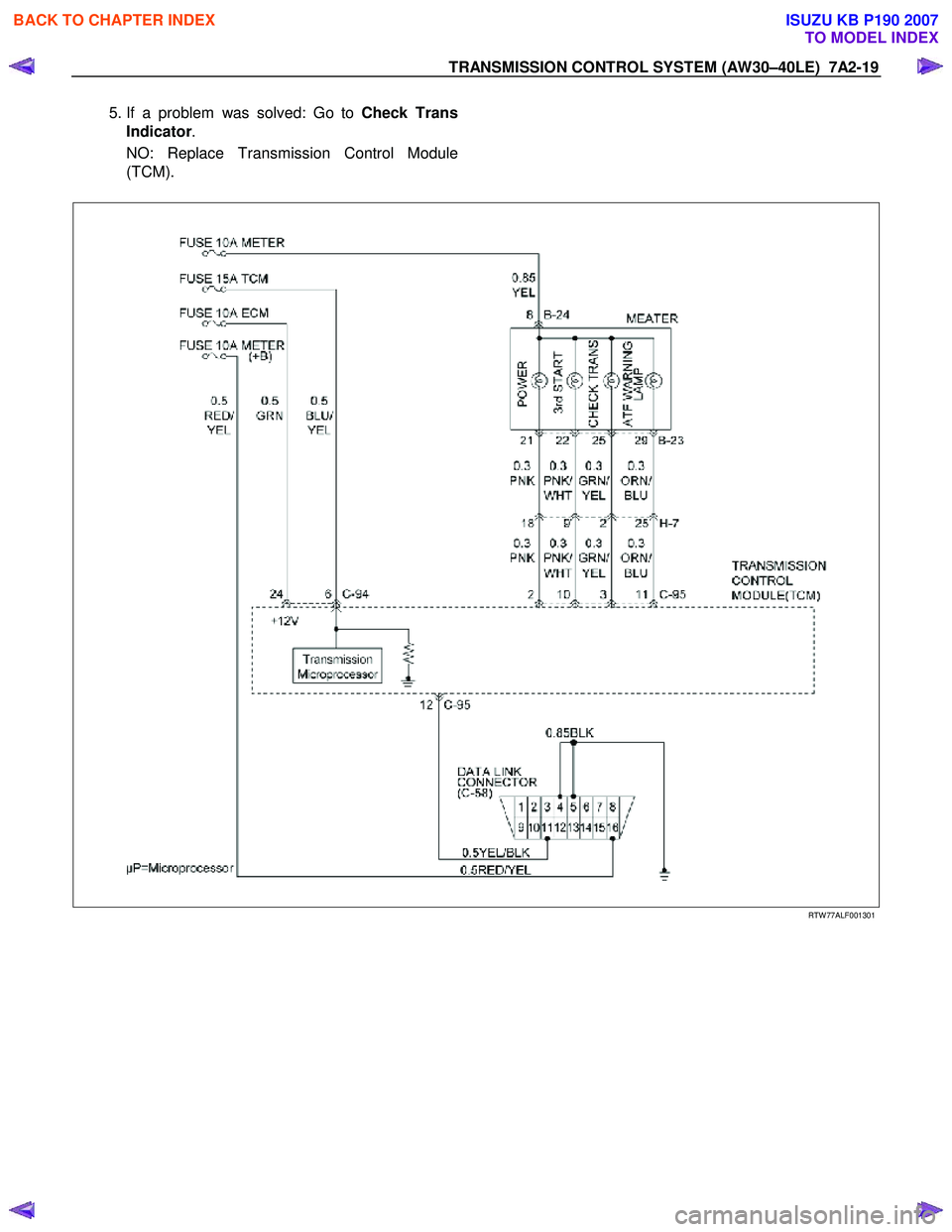
5. If a problem was solved: Go to Check Trans
Indicator .
NO: Replace Transmission Control Module
(TCM).
RTW 77ALF001301
BACK TO CHAPTER INDEX
TO MODEL INDEX
ISUZU KB P190 2007