indicator ISUZU KB P190 2007 Workshop Repair Manual
[x] Cancel search | Manufacturer: ISUZU, Model Year: 2007, Model line: KB P190, Model: ISUZU KB P190 2007Pages: 6020, PDF Size: 70.23 MB
Page 4005 of 6020

TRANSMISSION CONTROL SYSTEM (AW30–40LE) 7A2-39
Diagnostic Trouble Code (DTC) Type
Definitions
Emission Related DTC
Action Taken When the DTC Sets - Type A
• The Engine Control Module (ECM) illuminates the
malfunction indicator lamp (MIL) when the
diagnostic runs and fails.
• The ECM records the operating conditions at the
time the diagnostic fails. The ECM stores this
information in the Freeze Frame/ Failure Records.
Action Taken When the DTC Sets - Type B
• The ECM illuminates the MIL on the second
consecutive driving cycle when the diagnostic runs
and fails.
• The ECM records the operating conditions at the
time the diagnostic fails, the ECM stores this
information in the Failure Records. If the
diagnostic reports a failure on the second
consecutive driving cycle, the ECM records the
operating conditions at the time of failure and
stores this information in the Freeze Frame and
updates the Failure Records.
Conditions for Clearing the MIL/ DTC - Type A o
r
Type B • The ECM turns OFF the MIL after 3 consecutive
driving cycles when the diagnostic runs and does
not fail. (Euro 4 Specification)
• The ECM turns OFF the MIL after 1 driving cycle
when the diagnostic runs and does not fail.
(Except Euro 4 Specification)
•
A current DTC clears when the diagnostic runs
and passes after 1 driving cycle.
• A history DTC clears after 40 consecutive warm-
up cycles, if no failures are reported.
• Use a scan tool to clear the MIL and the DTC.
Non-Emissions Related DTCs
Action Taken When the DTC Sets - Type C or Type
D
• The TCM illuminates the Check Trans lamp when
the diagnostic runs and fails.
• The TCM records the operating conditions at the
time the diagnostic fails. The TCM stores this
information in the Failure Records.
• The TCM illuminates the Check Trans on the
second consecutive driving cycle when the
diagnostic runs and fails.
• The TCM records the operating conditions at the
time the diagnostic fails, the TCM stores this
information in the Failure Records. If the
diagnostic reports a failure on the second
consecutive driving cycle, the TCM records the
operating conditions at the time of failure and
stores this information in the Freeze Frame and
updates the Failure Records.
Conditions for Clearing the Check Trans Lamp/ DTC
- Type C or Type D
• The TCM turns OFF the Check Trans lamp after 1
driving cycle when the diagnostic runs and does
not fail.
•
A current DTC clears when the diagnostic runs
and passes after 3 driving cycle.
• A history DTC clears after 40 consecutive warm-
up cycles, if no failures are reported.
• Use a scan tool to clear the Check Trans lamp and
the DTC.
Action Taken When the DTC Sets - Type E or Type F • The TCM will not illuminate the Check Trans lamp.
• The TCM records the operating conditions at the
time the diagnostic fails. The TCM stores this
information in the Failure Records.
Conditions for Clearing the DTC - Type E or Type F •
A current DTC clears when the diagnostic runs
and passes after 1 driving cycle.
• A history DTC clears after 40 consecutive warm-
up cycles, if no failures are reported.
• Use a scan tool to clear the DTC.
BACK TO CHAPTER INDEX
TO MODEL INDEX
ISUZU KB P190 2007
Page 4110 of 6020
ON-VEHICLE SERVICE (AW30–40LE) 7A3-25
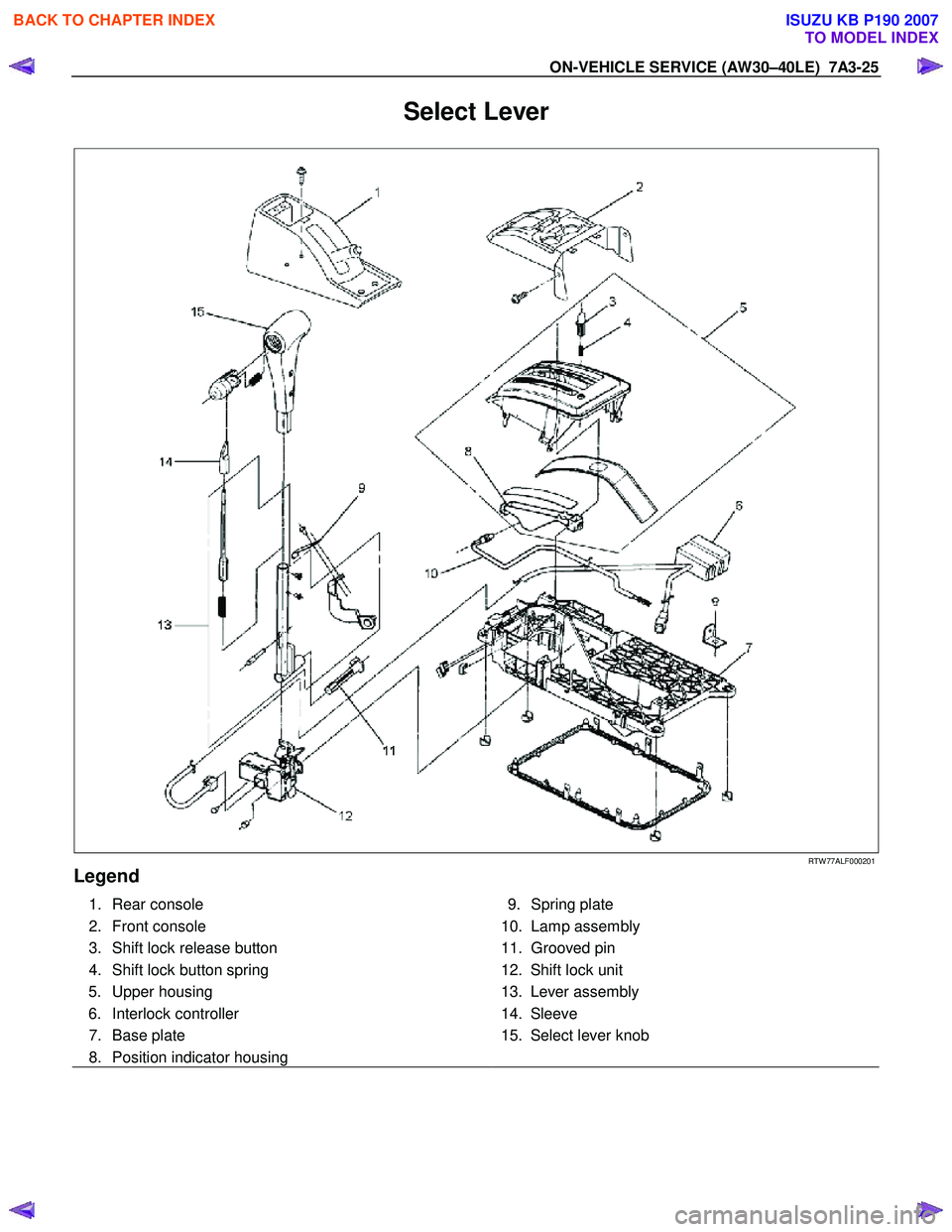
Select Lever
RTW 77ALF000201
Legend
1. Rear console
2. Front console
3. Shift lock release button
4. Shift lock button spring 5. Upper housing
6. Interlock controller
7. Base plate
8. Position indicator housing
9. Spring plate
10. Lamp assembly
11. Grooved pin
12. Shift lock unit
13. Lever assembly
14. Sleeve
15. Select lever knob
BACK TO CHAPTER INDEX
TO MODEL INDEX
ISUZU KB P190 2007
Page 4111 of 6020
7A3-26 ON-VEHICLE SERVICE (AW30–40LE)
Remove or Disconnect
1. Block the wheels.
2. Disconnect the negative battery cable.
3. Remove the rear console and the front console.
4. Remove the 2 screws fixing the select lever knob.
5. Remove the knob together with the knob button and spring from the lever.
6. Turn the sleeve counterclockwise to remove it. Make a note of the number of turns required to free
the sleeve.
7. Remove the harness connectors from the base plate.
8. Remove the upper housing (held in place by 4 latched fasteners).
9. Remove the lamp assembly by turning it counterclockwise.
10. Remove the spring plate.
11. Remove the grooved pin.
12. Disconnect the shift cable from the select lever.
13. Remove the lever assembly by pressing the rod down (lever in N position).
14. Remove the harness connectors from the shift lock unit, then remove the shift lock unit.
15. Remove the interlock controller.
16. If the replacement of shift lock release button o
r
shift lock button spring is required, remove the
position indicator housing, the shift lock button
spring and shift lock release button can be
removed.
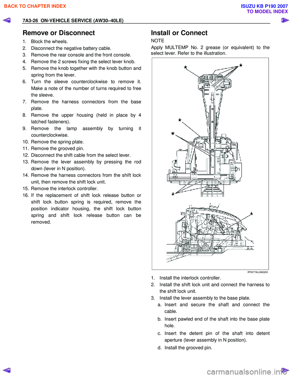
Install or Connect
NOTE
Apply MULTEMP No. 2 grease (or equivalent) to the
select lever. Refer to the illustration.
RTW 77ALH000201
1. Install the interlock controller.
2. Install the shift lock unit and connect the harness to the shift lock unit.
3. Install the lever assembly to the base plate. a. Insert and secure the shaft and connect the cable.
b. Insert pawled end of the shaft into the base plate hole.
c. Insert the detent pin of the shaft into detent aperture (lever assembly in N position).
d. Install the grooved pin.
BACK TO CHAPTER INDEX
TO MODEL INDEX
ISUZU KB P190 2007
Page 4152 of 6020
UNIT REPAIR (AW30–40LE) 7A4–17
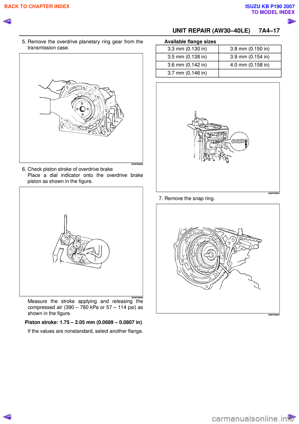
5. Remove the overdrive planetary ring gear from thetransmission case.
252RY00002
6. Check piston stroke of overdrive brakePlace a dial indicator onto the overdrive brake
piston as shown in the figure.
252RY00003Measure the stroke applying and releasing the
compressed air (390 – 780 kPa or 57 – 114 psi) as
shown in the figure.
Piston stroke: 1.75 – 2.05 mm (0.0689 – 0.0807 in)
If the values are nonstandard, select another flange. Available flange sizes
244RY00001
7. Remove the snap ring.
246RY00001
3.3 mm (0.130 in) 3.8 mm (0.150 in)
3.5 mm (0.138 in) 3.9 mm (0.154 in)
3.6 mm (0.142 in) 4.0 mm (0.158 in)
3.7 mm (0.146 in)
BACK TO CHAPTER INDEX
TO MODEL INDEX
ISUZU KB P190 2007
Page 4167 of 6020
7A4–32 UNIT REPAIR (AW30–40LE)
Install and tighten the two bolts.
Torque: 25 N ·m (2.5 kgf ·m / 18 lb ·ft)
252RY00004
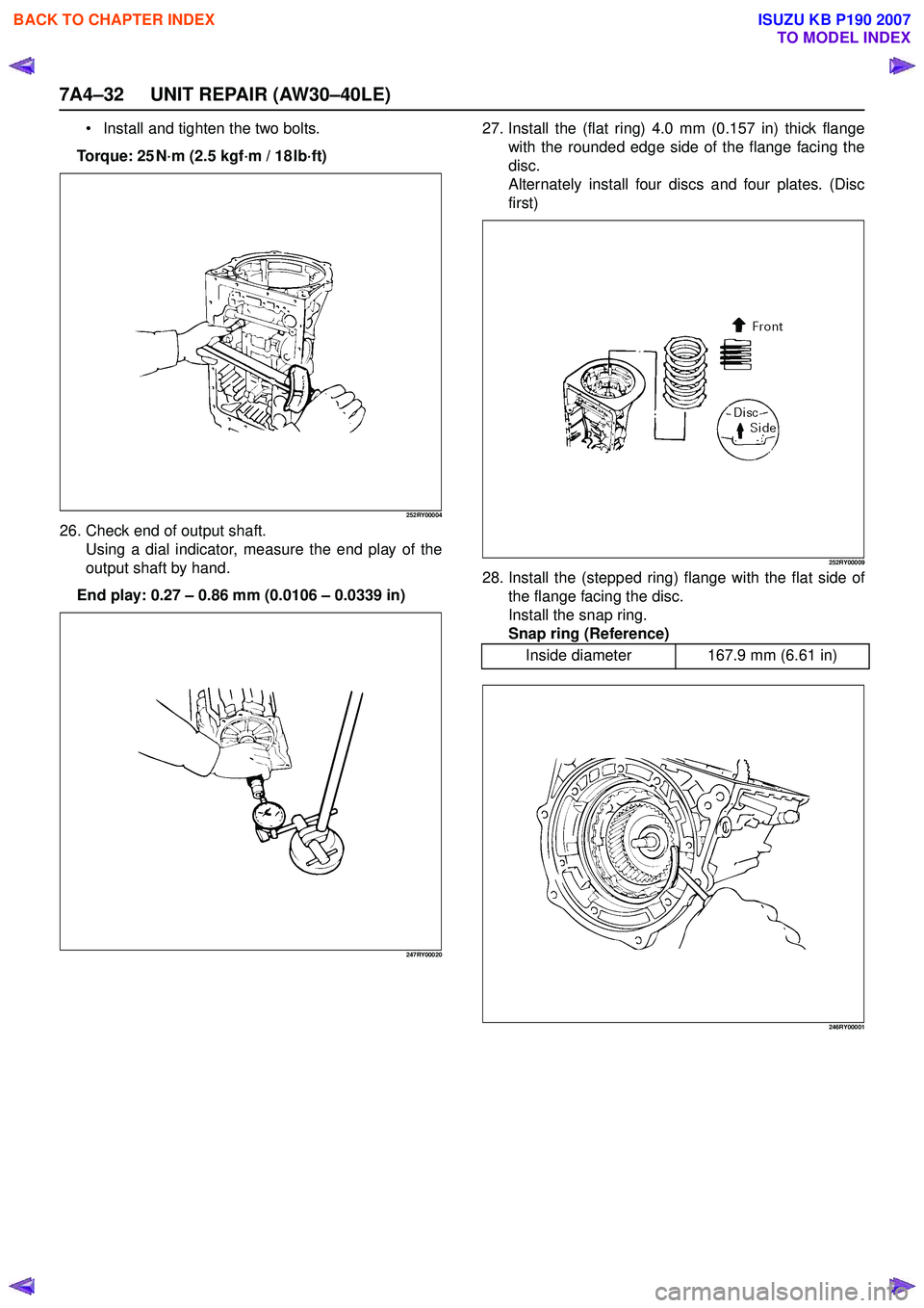
26. Check end of output shaft.
Using a dial indicator, measure the end play of the
output shaft by hand.
End play: 0.27 – 0.86 mm (0.0106 – 0.0339 in)
247RY00020
27. Install the (flat ring) 4.0 mm (0.157 in) thick flange
with the rounded edge side of the flange facing the
disc.
Alternately install four discs and four plates. (Disc
first)
252RY00009
28. Install the (stepped ring) flange with the flat side of the flange facing the disc.
Install the snap ring.
Snap ring (Reference)
246RY00001
Inside diameter 167.9 mm (6.61 in)
BACK TO CHAPTER INDEX
TO MODEL INDEX
ISUZU KB P190 2007
Page 4168 of 6020
UNIT REPAIR (AW30–40LE) 7A4–33
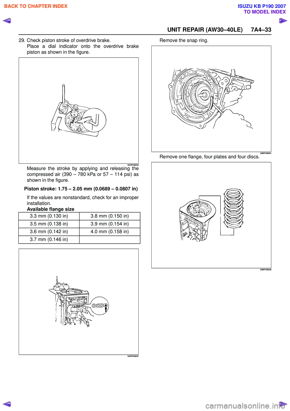
29. Check piston stroke of overdrive brake.Place a dial indicator onto the overdrive brake
piston as shown in the figure.
252RY00003Measure the stroke by applying and releasing the
compressed air (390 – 780 kPa or 57 – 114 psi) as
shown in the figure.
Piston stroke: 1.75 – 2.05 mm (0.0689 – 0.0807 in)
If the values are nonstandard, check for an improper
installation.
Available flange size
244RY00001
Remove the snap ring.
246RY00001Remove one flange, four plates and four discs.
246RY00026
3.3 mm (0.130 in) 3.8 mm (0.150 in)
3.5 mm (0.138 in) 3.9 mm (0.154 in)
3.6 mm (0.142 in) 4.0 mm (0.158 in)
3.7 mm (0.146 in)
BACK TO CHAPTER INDEX
TO MODEL INDEX
ISUZU KB P190 2007
Page 4173 of 6020
7A4–38 UNIT REPAIR (AW30–40LE)
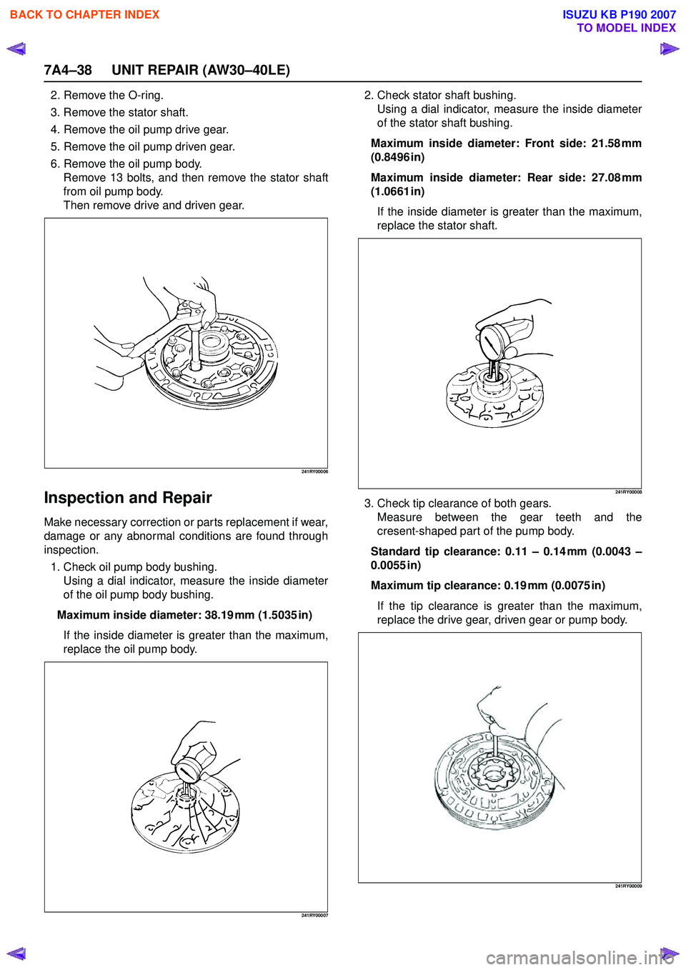
2. Remove the O-ring.
3. Remove the stator shaft.
4. Remove the oil pump drive gear.
5. Remove the oil pump driven gear.
6. Remove the oil pump body. Remove 13 bolts, and then remove the stator shaft
from oil pump body.
Then remove drive and driven gear.
241RY00006
Inspection and Repair
Make necessary correction or parts replacement if wear,
damage or any abnormal conditions are found through
inspection.
1. Check oil pump body bushing. Using a dial indicator, measure the inside diameter
of the oil pump body bushing.
Maximum inside diameter: 38.19 mm (1.5035 in) If the inside diameter is greater than the maximum,
replace the oil pump body.
241RY00007
2. Check stator shaft bushing. Using a dial indicator, measure the inside diameter
of the stator shaft bushing.
Maximum inside diameter: Front side: 21.58 mm
(0.8496 in)
Maximum inside diameter: Rear side: 27.08 mm
(1.0661 in)
If the inside diameter is greater than the maximum,
replace the stator shaft.
241RY00008
3. Check tip clearance of both gears. Measure between the gear teeth and the
cresent-shaped part of the pump body.
Standard tip clearance: 0.11 – 0.14 mm (0.0043 –
0.0055 in)
Maximum tip clearance: 0.19 mm (0.0075 in) If the tip clearance is greater than the maximum,
replace the drive gear, driven gear or pump body.
241RY00009
BACK TO CHAPTER INDEX
TO MODEL INDEX
ISUZU KB P190 2007
Page 4178 of 6020
UNIT REPAIR (AW30–40LE) 7A4–43
Disassembly
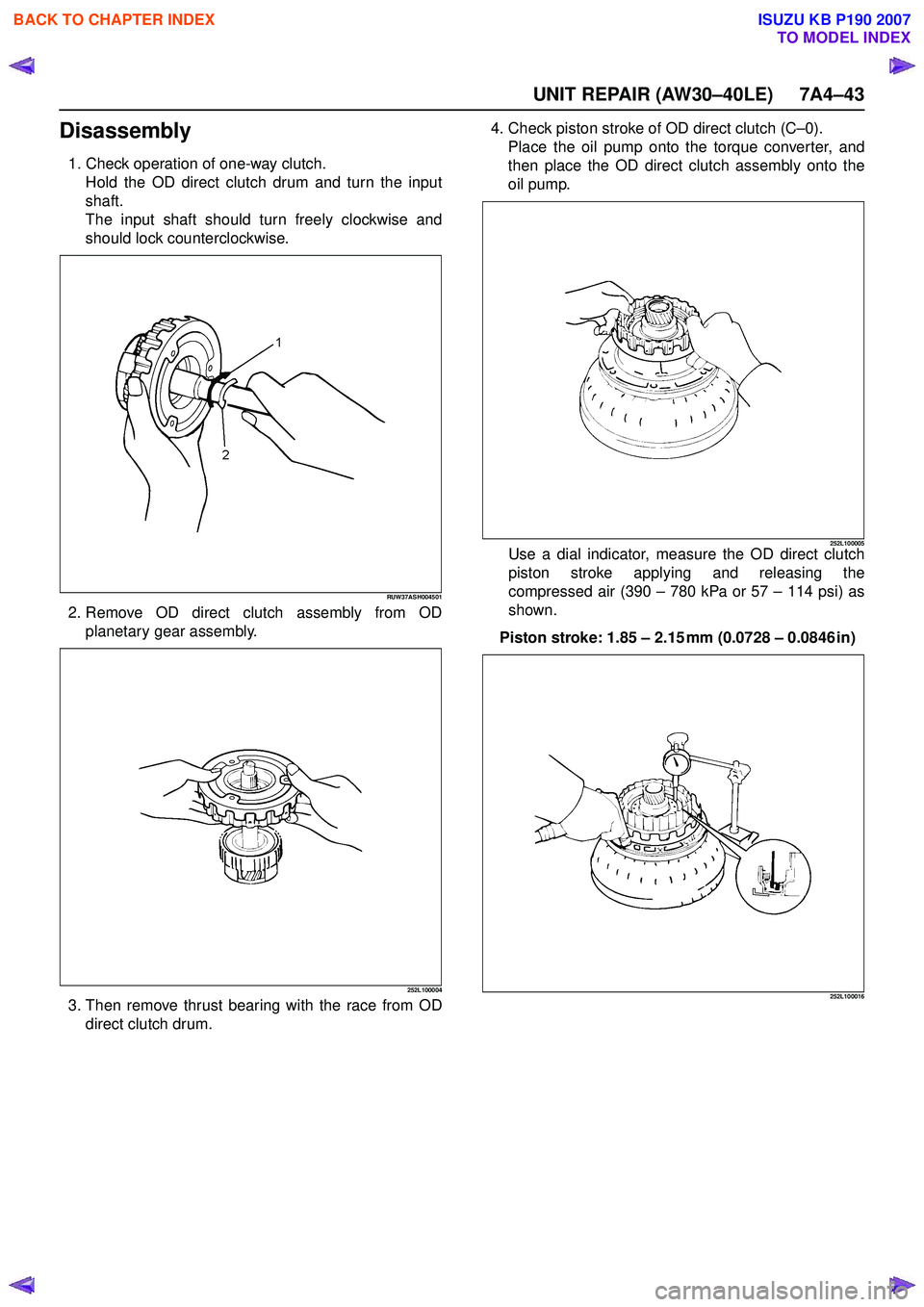
1. Check operation of one-way clutch.Hold the OD direct clutch drum and turn the input
shaft.
The input shaft should turn freely clockwise and
should lock counterclockwise.
RUW37ASH004501
2. Remove OD direct clutch assembly from OD planetary gear assembly.
252L100004
3. Then remove thrust bearing with the race from ODdirect clutch drum. 4. Check piston stroke of OD direct clutch (C
–0).
Place the oil pump onto the torque converter, and
then place the OD direct clutch assembly onto the
oil pump.
252L100005Use a dial indicator, measure the OD direct clutch
piston stroke applying and releasing the
compressed air (390 – 780 kPa or 57 – 114 psi) as
shown.
Piston stroke: 1.85 – 2.15 mm (0.0728 – 0.0846 in)
252L100016
BACK TO CHAPTER INDEX
TO MODEL INDEX
ISUZU KB P190 2007
Page 4181 of 6020
7A4–46 UNIT REPAIR (AW30–40LE)
18. Remove the thrust washer.
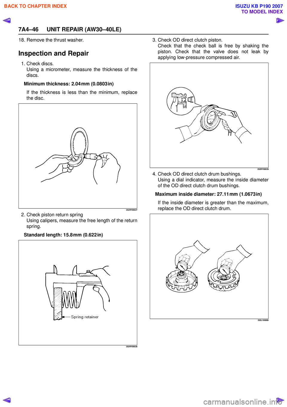
Inspection and Repair
1. Check discs.Using a micrometer, measure the thickness of the
discs.
Minimum thickness: 2.04 mm (0.0803 in) If the thickness is less than the minimum, replace
the disc.
252RY00027
2. Check piston return spring Using calipers, measure the free length of the return
spring.
Standard length: 15.8 mm (0.622 in)
252RY00028
3. Check OD direct clutch piston. Check that the check ball is free by shaking the
piston. Check that the valve does not leak by
applying low-pressure compressed air.
252RY00029
4. Check OD direct clutch drum bushings. Using a dial indicator, measure the inside diameter
of the OD direct clutch drum bushings.
Maximum inside diameter: 27.11 mm (1.0673 in) If the inside diameter is greater than the maximum,
replace the OD direct clutch drum.
252L100009
BACK TO CHAPTER INDEX
TO MODEL INDEX
ISUZU KB P190 2007
Page 4182 of 6020
UNIT REPAIR (AW30–40LE) 7A4–47
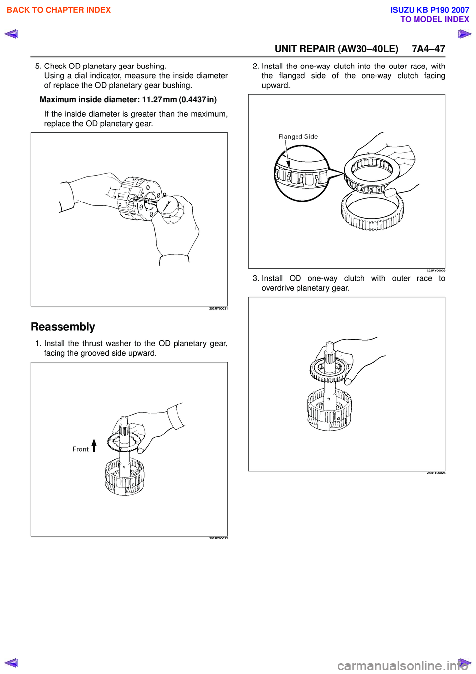
5. Check OD planetary gear bushing.Using a dial indicator, measure the inside diameter
of replace the OD planetary gear bushing.
Maximum inside diameter: 11.27 mm (0.4437 in) If the inside diameter is greater than the maximum,
replace the OD planetary gear.
252RY00031
Reassembly
1. Install the thrust washer to the OD planetary gear, facing the grooved side upward.
252RY00032
2. Install the one-way clutch into the outer race, withthe flanged side of the one-way clutch facing
upward.
252RY00033
3. Install OD one-way clutch with outer race to overdrive planetary gear.
252RY00026
BACK TO CHAPTER INDEX
TO MODEL INDEX
ISUZU KB P190 2007