ISUZU KB P190 2007 Workshop Repair Manual
Manufacturer: ISUZU, Model Year: 2007, Model line: KB P190, Model: ISUZU KB P190 2007Pages: 6020, PDF Size: 70.23 MB
Page 2491 of 6020

Engine Mechanical – V6 Page 6A1–12
Engine Front Cover
Figure 6A1 – 4
Legend
1 Engine Front Cover Locating Pin
2 Engine Front Cover Bolt, M10
3 Engine Front Cover
4 Engine Front Cover Gasket
5 Engine Front Cover Bolt, M8
6 Engine Front Cover Seal
7 Coolant Pump Assembly
8 Coolant Pump Bolt
9 Coolant Pump Gasket 10 Coolant Pump Pulley
11 Coolant Pump Pulley Bolt
12 Crankshaft Balancer
13 Crankshaft Balancer Bolt
14 Camshaft Position Sensor
15 Camshaft Position Sensor O-ring
16 Camshaft Position Sensor Bolt
17 Camshaft Position Actuator Solenoid Valve Seal
BACK TO CHAPTER INDEX
TO MODEL INDEX
ISUZU KB P190 2007
Page 2492 of 6020
Engine Mechanical – V6 Page 6A1–13
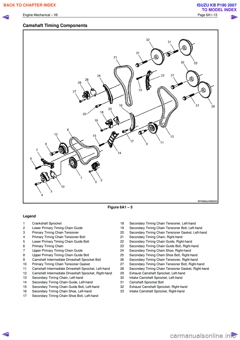
Camshaft Timing Components
Figure 6A1 – 5
Legend
1 Crankshaft Sprocket
2 Lower Primary Timing Chain Guide
3 Primary Timing Chain Tensioner
4 Primary Timing Chain Tensioner Bolt
5 Lower Primary Timing Chain Guide Bolt
6 Primary Timing Chain
7 Upper Primary Timing Chain Guide
8 Upper Primary Timing Chain Guide Bolt
9 Camshaft Intermediate Driveshaft Sprocket Bolt
10 Primary Timing Chain Tensioner Gasket
11 Camshaft Intermediate Driveshaft Sprocket, Left-hand
12 Camshaft Intermediate Driveshaft Sprocket, Right-hand
13 Secondary Timing Chain, Left-hand
14 Secondary Timing Chain Guide, Left-hand
15 Secondary Timing Chain Guide Bolt, Left-hand
16 Secondary Timing Chain Shoe, Left-hand
17 Secondary Timing Chain Shoe Bolt, Left-hand 18 Secondary Timing Chain Tensioner, Left-hand
19 Secondary Timing Chain Tensioner Bolt, Left-hand
20 Secondary Timing Chain Tensioner Gasket, Left-hand
21 Secondary Timing Chain, Right-hand
22 Secondary Timing Chain Guide, Right-hand
23 Secondary Timing Chain Guide Bolt, Right-hand
24 Secondary Timing Chain Shoe, Right-hand
25 Secondary Timing Chain Shoe Bolt, Right-hand
26 Secondary Timing Chain Tensioner, Right-hand
27 Secondary Timing Chain Tensioner Bolt, Right-hand
28 Secondary Timing Chain Tensioner Gasket, Right-hand
29 Exhaust Camshaft Sprocket, Left-hand
30 Intake Camshaft Sprocket, Left-hand
31 Camshaft Sprocket Bolt
32 Exhaust Camshaft Sprocket, Right-hand
33 Intake Camshaft Sprocket, Right-hand
BACK TO CHAPTER INDEX
TO MODEL INDEX
ISUZU KB P190 2007
Page 2493 of 6020
Engine Mechanical – V6 Page 6A1–14
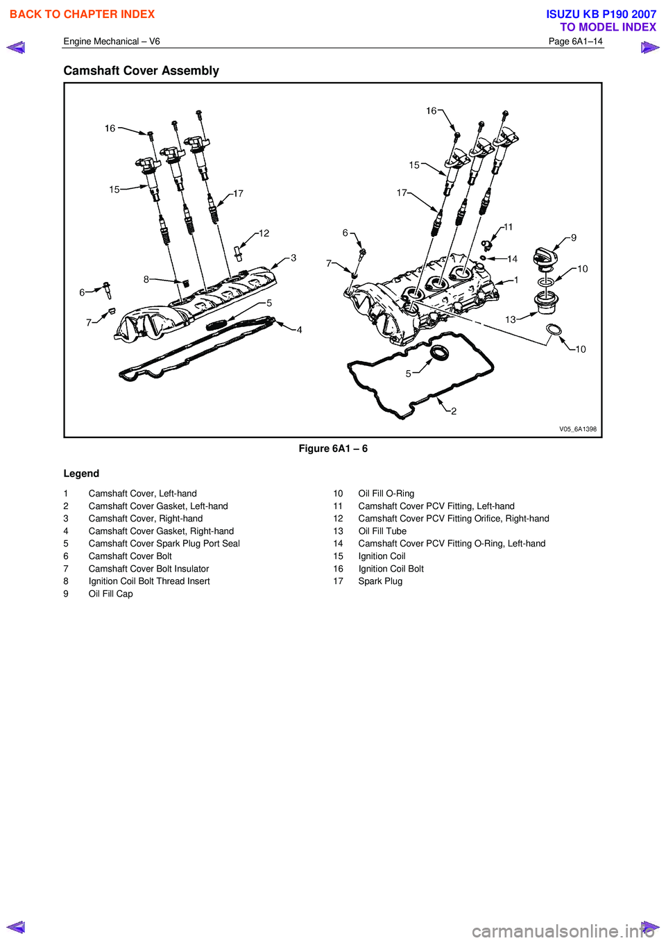
Camshaft Cover Assembly
Figure 6A1 – 6
Legend
1 Camshaft Cover, Left-hand
2 Camshaft Cover Gasket, Left-hand
3 Camshaft Cover, Right-hand
4 Camshaft Cover Gasket, Right-hand
5 Camshaft Cover Spark Plug Port Seal
6 Camshaft Cover Bolt
7 Camshaft Cover Bolt Insulator
8 Ignition Coil Bolt Thread Insert
9 Oil Fill Cap 10 Oil Fill O-Ring
11 Camshaft Cover PCV Fitting, Left-hand
12 Camshaft Cover PCV Fitting Orifice, Right-hand
13 Oil Fill Tube
14 Camshaft Cover PCV Fitting O-Ring, Left-hand
15 Ignition Coil
16 Ignition Coil Bolt
17 Spark Plug
BACK TO CHAPTER INDEX
TO MODEL INDEX
ISUZU KB P190 2007
Page 2494 of 6020

Engine Mechanical – V6 Page 6A1–15
Cylinder Head Assembly
Figure 6A1 – 7
Legend
1 Cylinder Head, Left-hand
2 Cylinder Head, Right-hand
3 Cylinder Head Gasket, Left-hand
4 Cylinder Head Gasket, Right-hand
5 Cylinder Head Bolt
6 Cylinder Head Front Bolt
7 Cylinder Head Coolant Hole Threaded Plug
8 Spark Plug Sleeve
9 Cylinder Head Oil Gallery Expansion Plug
10 Exhaust Valve
11 Intake Valve
12 Valve Rocker Arm Assembly
13 Hydraulic Valve Lash Adjuster Assembly
14 Valve Stem Oil Seal 15 Valve Spring
16 Valve Spring Cap
17 Valve Stem Key
18 Cylinder Head Camshaft Front Thrust Bearing Cap
19 Camshaft Oil Seal Ring
20 Exhaust Camshaft
21 Intake Camshaft, Left-hand (bank 2)
22 Intake Camshaft, Right-hand (bank 1)
23 Exhaust Camshaft, Right-hand (bank 1)
24 Cylinder Head Camshaft Cap – Intermediate
25 Cylinder Head Camshaft Cap Bolt
26 Cylinder Head Oil Galley Check Valve
27 Engine Coolant Temperature Sensor
BACK TO CHAPTER INDEX
TO MODEL INDEX
ISUZU KB P190 2007
Page 2495 of 6020
Engine Mechanical – V6 Page 6A1–16
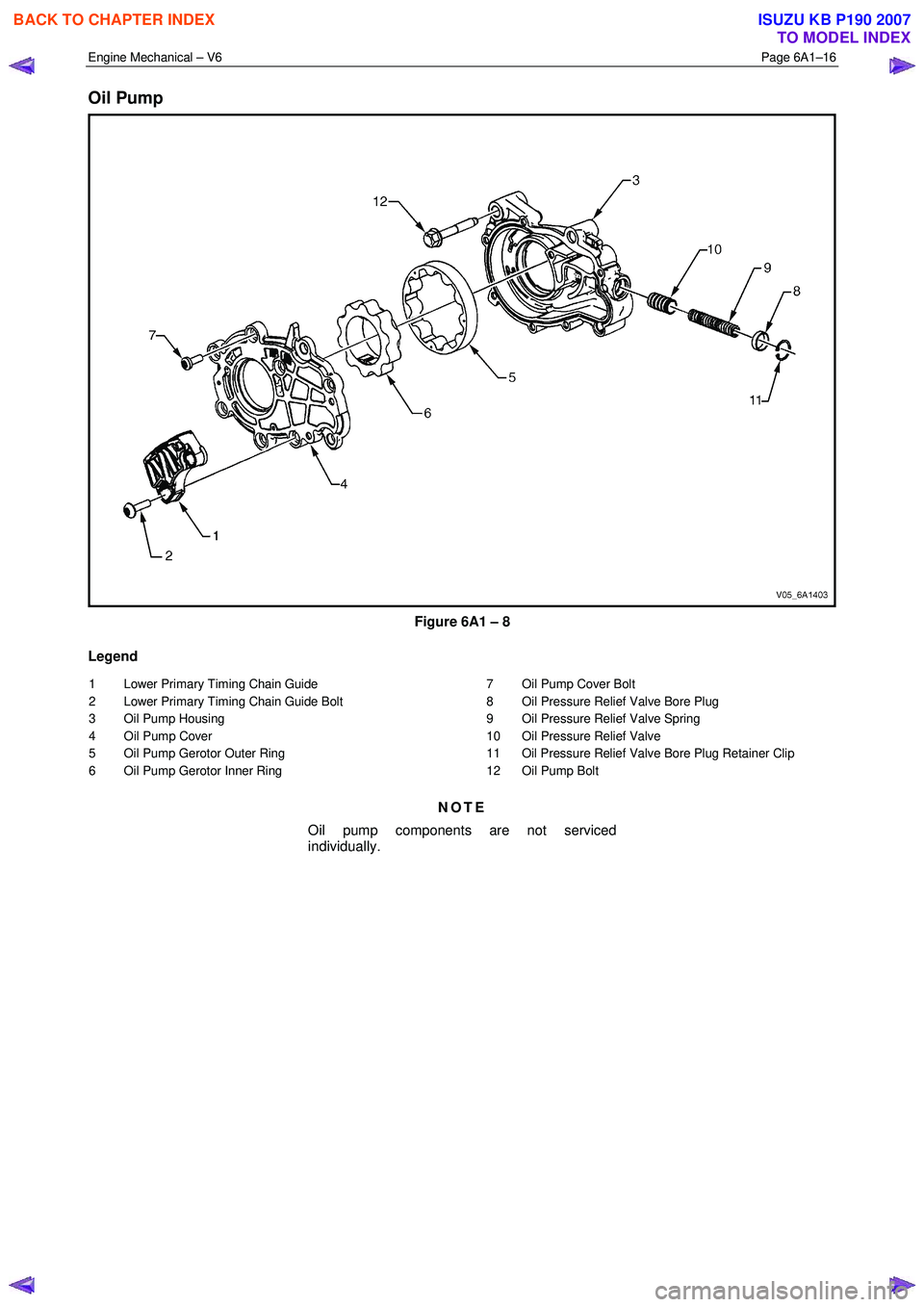
Oil Pump
Figure 6A1 – 8
Legend
1 Lower Primary Timing Chain Guide
2 Lower Primary Timing Chain Guide Bolt
3 Oil Pump Housing
4 Oil Pump Cover
5 Oil Pump Gerotor Outer Ring
6 Oil Pump Gerotor Inner Ring 7 Oil Pump Cover Bolt
8 Oil Pressure Relief Valve Bore Plug
9 Oil Pressure Relief Valve Spring
10 Oil Pressure Relief Valve
11 Oil Pressure Relief Valve Bore Plug Retainer Clip
12 Oil Pump Bolt
NOTE
Oil pump components are not serviced
individually.
BACK TO CHAPTER INDEX
TO MODEL INDEX
ISUZU KB P190 2007
Page 2496 of 6020

Engine Mechanical – V6 Page 6A1–17
Engine Block Assembly
Figure 6A1 – 9
Legend
1 Piston and Connecting Rod Assembly
2 Crankshaft Bearing Cap
3 Crankshaft Bearing Thrust Cap
4 Crankshaft Bearing Cap Inboard Bolt
5 Crankshaft Bearing Cap Outboard Bolt
6 Crankshaft Bearing Cap Side Bolt, Short
7 Crankshaft Bearing Cap Side Bolt, Long
8 Engine Block Oil Gallery Expansion Plug, 10 mm
9 Crankshaft
10 Crankshaft Sprocket Locating Pin
11 Crankshaft Upper Bearing
12 Crankshaft Lower Bearing
13 Crankshaft Upper Thrust Bearing #3 14 Engine Block Oil Gallery Expansion Plug, 14 mm
15 Engine Block Oil Gallery Threaded Plug, 14 mm
16 Engine Block Coolant Drain Threaded Plug, 14 mm
17 Engine Block Oil Gallery Threaded Plug, 20 mm
18 Engine Block Core Coolant Expansion Plug, 34.3 mm
19 Transaxle Locating Pin
20 Crankshaft Rear Oil Seal Housing Assembly
21 Crankshaft Rear Oil Seal Housing Assembly Bolt
22 Oil Pan Locating Pin
23 Cylinder Head Locating Pin
24 Piston Oil Nozzle
25 Piston Oil Nozzle Bolt
BACK TO CHAPTER INDEX
TO MODEL INDEX
ISUZU KB P190 2007
Page 2497 of 6020
Engine Mechanical – V6 Page 6A1–18
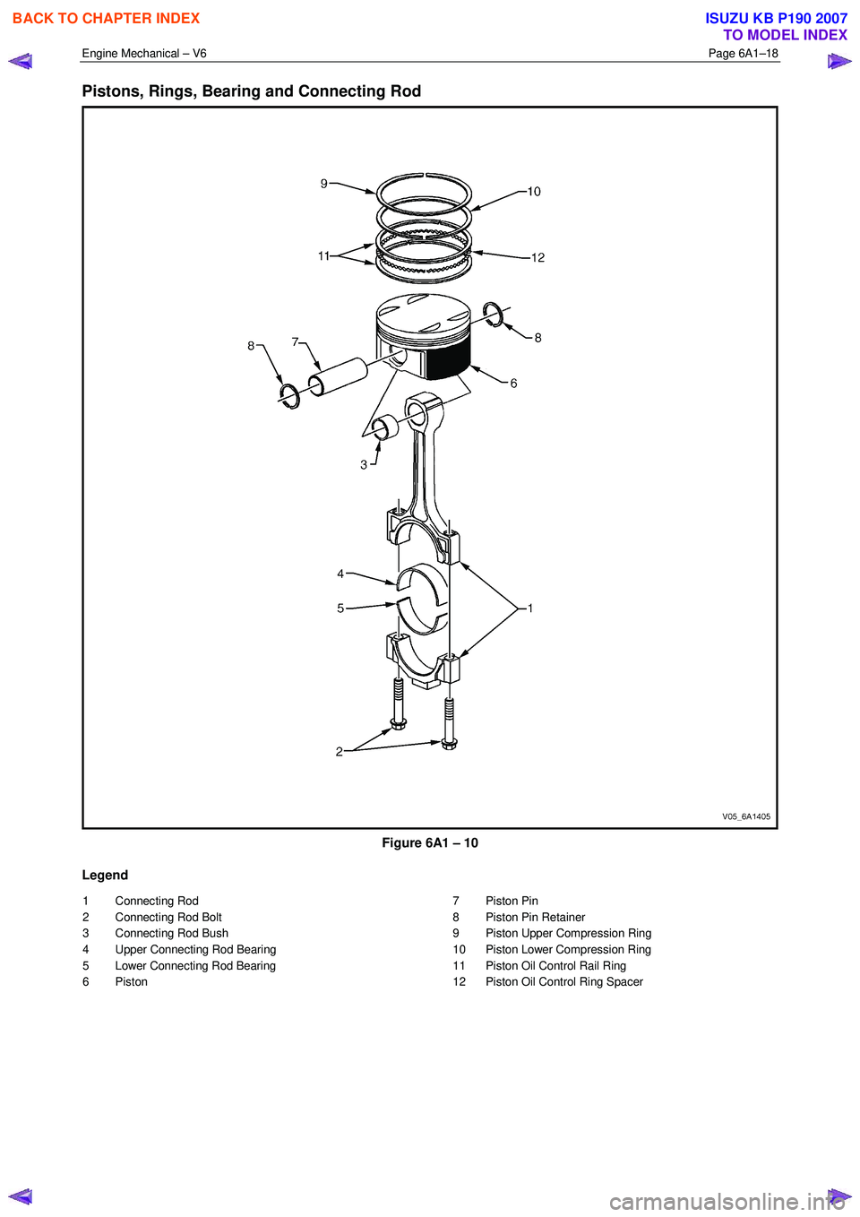
Pistons, Rings, Bearing and Connecting Rod
Figure 6A1 – 10
Legend
1 Connecting Rod
2 Connecting Rod Bolt
3 Connecting Rod Bush
4 Upper Connecting Rod Bearing
5 Lower Connecting Rod Bearing
6 Piston 7 Piston Pin
8 Piston Pin Retainer
9 Piston Upper Compression Ring
10 Piston Lower Compression Ring
11 Piston Oil Control Rail Ring
12 Piston Oil Control Ring Spacer
BACK TO CHAPTER INDEX
TO MODEL INDEX
ISUZU KB P190 2007
Page 2498 of 6020
Engine Mechanical – V6 Page 6A1–19
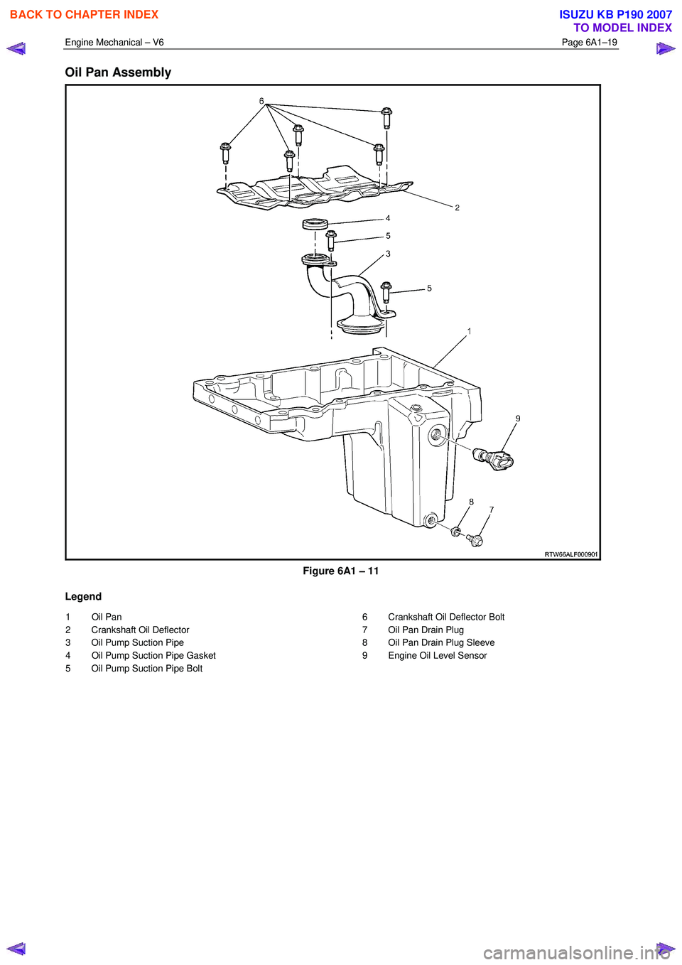
Oil Pan Assembly
Figure 6A1 – 11
Legend
1 Oil Pan
2 Crankshaft Oil Deflector
3 Oil Pump Suction Pipe
4 Oil Pump Suction Pipe Gasket
5 Oil Pump Suction Pipe Bolt 6 Crankshaft Oil Deflector Bolt
7 Oil Pan Drain Plug
8 Oil Pan Drain Plug Sleeve
9 Engine Oil Level Sensor
BACK TO CHAPTER INDEX
TO MODEL INDEX
ISUZU KB P190 2007
Page 2499 of 6020
Engine Mechanical – V6 Page 6A1–20
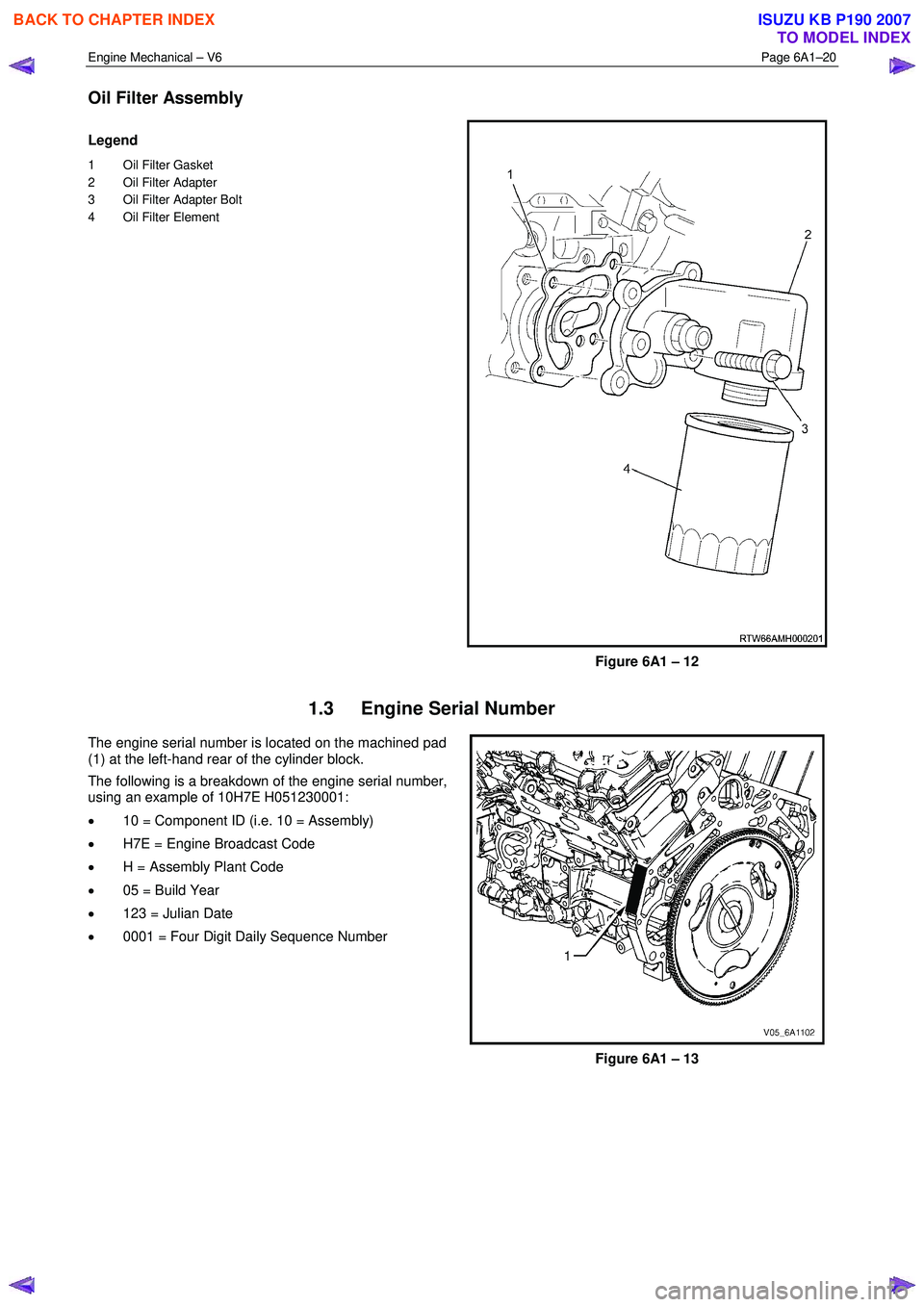
Oil Filter Assembly
Legend
1 Oil Filter Gasket
2 Oil Filter Adapter
3 Oil Filter Adapter Bolt
4 Oil Filter Element
Figure 6A1 – 12
1.3 Engine Serial Number
The engine serial number is located on the machined pad
(1) at the left-hand rear of the cylinder block.
The following is a breakdown of the engine serial number,
using an example of 10H7E H051230001:
• 10 = Component ID (i.e. 10 = Assembly)
• H7E = Engine Broadcast Code
• H = Assembly Plant Code
• 05 = Build Year
• 123 = Julian Date
• 0001 = Four Digit Daily Sequence Number
Figure 6A1 – 13
BACK TO CHAPTER INDEX
TO MODEL INDEX
ISUZU KB P190 2007
Page 2500 of 6020
Engine Mechanical – V6 Page 6A1–21
1.4 Engine Construction
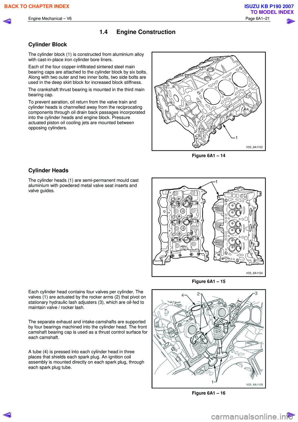
Cylinder Block
The cylinder block (1) is constructed from aluminium alloy
with cast-in-place iron cylinder bore liners.
Each of the four copper-infiltrated sintered steel main
bearing caps are attached to the cylinder block by six bolts.
Along with two outer and two inner bolts, two side bolts are
used in the deep skirt block for increased block stiffness.
The crankshaft thrust bearing is mounted in the third main
bearing cap.
To prevent aeration, oil return from the valve train and
cylinder heads is channelled away from the reciprocating
components through oil drain back passages incorporated
into the cylinder heads and engine block. Pressure
actuated piston oil cooling jets are mounted between
opposing cylinders.
Figure 6A1 – 14
Cylinder Heads
The cylinder heads (1) are semi-permanent mould cast
aluminium with powdered metal valve seat inserts and
valve guides.
Figure 6A1 – 15
Each cylinder head contains four valves per cylinder. The
valves (1) are actuated by the rocker arms (2) that pivot on
stationary hydraulic lash adjusters (3), which are oil-fed to
maintain valve / rocker lash.
The separate exhaust and intake camshafts are supported
by four bearings machined into the cylinder head. The front
camshaft bearing cap is used as a thrust control surface for
each camshaft.
A tube (4) is pressed into each cylinder head in three
places that shields each spark plug. An ignition coil
assembly is mounted directly on each spark plug, through
each spark plug tube.
Figure 6A1 – 16
BACK TO CHAPTER INDEX
TO MODEL INDEX
ISUZU KB P190 2007