front differential ISUZU KB P190 2007 Workshop Owner's Manual
[x] Cancel search | Manufacturer: ISUZU, Model Year: 2007, Model line: KB P190, Model: ISUZU KB P190 2007Pages: 6020, PDF Size: 70.23 MB
Page 541 of 6020
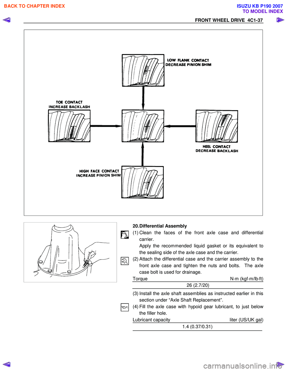
FRONT WHEEL DRIVE 4C1-37
20. Differential Assembly
(1) Clean the faces of the front axle case and differential carrier.
Apply the recommended liquid gasket or its equivalent to
the sealing side of the axle case and the carrier.
(2)
Attach the differential case and the carrier assembly to the
front axle case and tighten the nuts and bolts. The axle
case bolt is used for drainage.
Torque N ⋅m (kgf ⋅m/lb ⋅ft)
26 (2.7/20)
(3) Install the axle shaft assemblies as instructed earlier in this section under “Axle Shaft Replacement”.
(4) Fill the axle case with hypoid gear lubricant, to just belo
w
the filler hole.
Lubricant capacity liter (US/UK gal)
1.4 (0.37/0.31)
BACK TO CHAPTER INDEX
TO MODEL INDEX
ISUZU KB P190 2007
Page 571 of 6020
FRONT WHEEL DRIVE 4C1-67
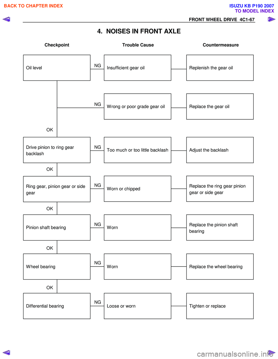
4. NOISES IN FRONT AXLE
Checkpoint Trouble Cause Countermeasure
Replenish the gear oilInsufficient gear oil
NG
Replace the wheel bearing
Replace the pinion shaft
bearing
Replace the ring gear pinion
gear or side gear
Replace the gear oil
W heel bearingWorn
Pinion shaft bearingWorn
W orn or chipped
W rong or poor grade gear oil
Ring gear, pinion gear or side
gear
Adjust the backlashDrive pinion to ring gear
backlashToo much or too little backlash
NG
NG
NG
NG
NG
OK
OK
OK
OK
Oil level
Tighten or replaceDifferential bearingLoose or worn
NG
OK
BACK TO CHAPTER INDEX
TO MODEL INDEX
ISUZU KB P190 2007
Page 588 of 6020

4C2-10 SHIFT ON THE FLY SYSTEM
412RS044
13. Inner Shaft Bearing
• Place a new snap ring in inner shaft.
• Force a new inner shaft bearing into the inner shaft.
Installer : 5-8840-2197-0
12. Snap Ring
NOTE;
Be careful not to damage the inner shaft.
11.inner Shaft • Clean the housing contact surface of the front axle
case.
• Insert inner shaft assembly into the front axle case.
NOTE:
Be careful not to damage oil seal.
412RW 017
10. Snap Ring
Install snap ring in the groove of front axle case.
NOTE:
Be sure to install the snap ring properly.
9. Clutch Gear Apply differential gear oil to clutch oil.
8. Sleeve Apply differential gear oil to sleeve.
412RW 023
7. Housing
• Clean contact surface with the front axle and actuato
r
mounting surface.
•
Apply liquid gasket to the contact surface on the front
axle case and install in the housing.
6. Bolt
Tighten bolts to specified tightening torque.
Housing Bolt Torque N⋅m (kgf ⋅m/lb ⋅ft)
75 (7.6/55)
BACK TO CHAPTER INDEX
TO MODEL INDEX
ISUZU KB P190 2007
Page 589 of 6020
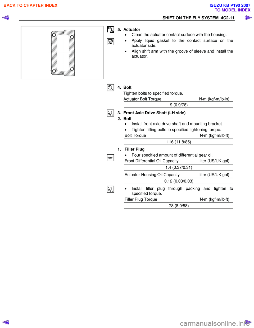
SHIFT ON THE FLY SYSTEM 4C2-11
5. Actuator • Clean the actuator contact surface with the housing.
•
Apply liquid gasket to the contact surface on the
actuator side.
• Align shift arm with the groove of sleeve and install the
actuator.
4. Bolt
Tighten bolts to specified torque.
Actuator Bolt Torque N⋅m (kgf ⋅m/lb ⋅in)
9 (0.9/78)
3. Front Axle Drive Shaft (LH side)
2. Bolt • Install front axle drive shaft and mounting bracket.
• Tighten fitting bolts to specified tightening torque.
Bolt Torque N⋅m (kgf ⋅m/lb ⋅ft)
116 (11.8/85)
1. Filler Plug • Pour specified amount of differential gear oil.
Front Differential Oil Capacity liter (US/UK gal)
1.4 (0.37/0.31)
Actuator Housing Oil Capacity liter (US/UK gal) 0.12 (0.03/0.03)
• Install filler plug through packing and tighten to
specified torque.
Filler Plug Torque N⋅m (kgf ⋅m/lb ⋅ft)
78 (8.0/58)
BACK TO CHAPTER INDEX
TO MODEL INDEX
ISUZU KB P190 2007
Page 657 of 6020
5A-64 BRAKE CONTROL SYSTEM
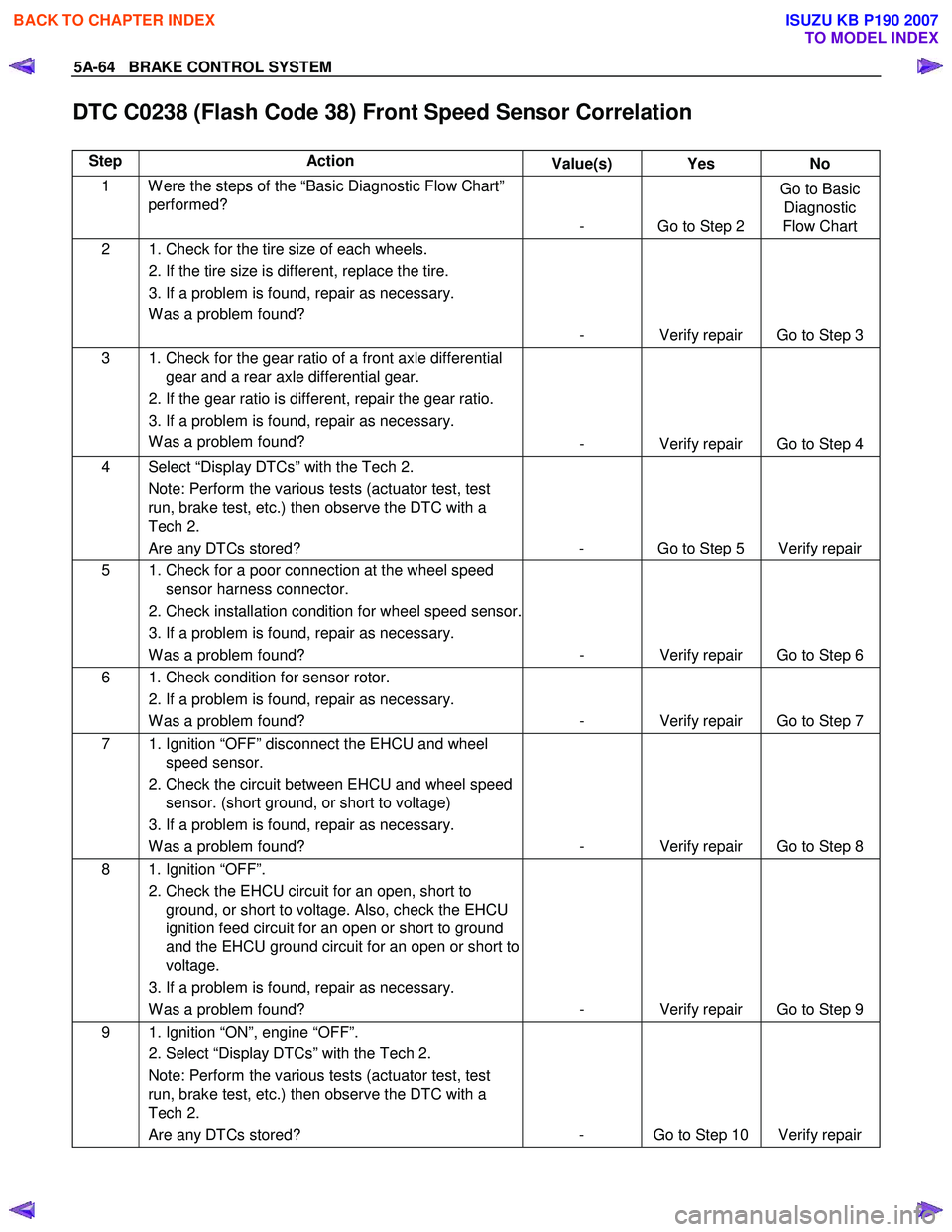
DTC C0238 (Flash Code 38) Front Speed Sensor Correlation
Step Action Value(s) Yes No
1 W ere the steps of the “Basic Diagnostic Flow Chart”
performed?
- Go to Step 2 Go to Basic
Diagnostic
Flow Chart
2 1. Check for the tire size of each wheels.
2. If the tire size is different, replace the tire.
3. If a problem is found, repair as necessary. W as a problem found? - Verify repair Go to Step 3
3 1. Check for the gear ratio of a front axle differential gear and a rear axle differential gear.
2. If the gear ratio is different, repair the gear ratio.
3. If a problem is found, repair as necessary. W as a problem found? - Verify repair Go to Step 4
4 Select “Display DTCs” with the Tech 2.
Note: Perform the various tests (actuator test, test
run, brake test, etc.) then observe the DTC with a
Tech 2.
Are any DTCs stored? - Go to Step 5 Verify repair
5 1. Check for a poor connection at the wheel speed sensor harness connector.
2. Check installation condition for wheel speed sensor.
3. If a problem is found, repair as necessary. W as a problem found? - Verify repair Go to Step 6
6 1. Check condition for sensor rotor.
2. If a problem is found, repair as necessary. W as a problem found? - Verify repair Go to Step 7
7 1. Ignition “OFF” disconnect the EHCU and wheel
speed sensor.
2. Check the circuit between EHCU and wheel speed sensor. (short ground, or short to voltage)
3. If a problem is found, repair as necessary. W as a problem found? - Verify repair Go to Step 8
8 1. Ignition “OFF”.
2. Check the EHCU circuit for an open, short to ground, or short to voltage. Also, check the EHCU
ignition feed circuit for an open or short to ground
and the EHCU ground circuit for an open or short to
voltage.
3. If a problem is found, repair as necessary. W as a problem found? - Verify repair Go to Step 9
9 1. Ignition “ON”, engine “OFF”.
2. Select “Display DTCs” with the Tech 2. Note: Perform the various tests (actuator test, test
run, brake test, etc.) then observe the DTC with a
Tech 2.
Are any DTCs stored? - Go to Step 10 Verify repair
BACK TO CHAPTER INDEX
TO MODEL INDEX
ISUZU KB P190 2007
Page 842 of 6020
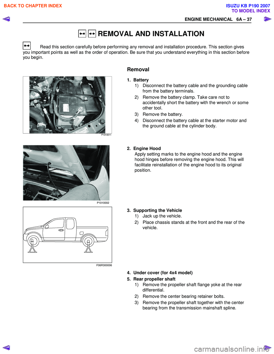
ENGINE MECHANICAL 6A – 37
REMOVAL AND INSTALLATION
Read this section carefully before performing any removal and installation procedure. This section gives
you important points as well as the order of operation. Be sure that you understand everything in this section before
you begin.
Removal
P1010011
1. Battery
1) Disconnect the battery cable and the grounding cable from the battery terminals.
2) Remove the battery clamp. Take care not to accidentally short the battery with the wrench or some
other tool.
3) Remove the battery.
4) Disconnect the battery cable at the starter motor and the ground cable at the cylinder body.
2. Engine Hood Apply setting marks to the engine hood and the engine
hood hinges before removing the engine hood. This will
facilitate reinstallation of the engine hood to its original
position.
3. Supporting the Vehicle 1) Jack up the vehicle.
2) Place chassis stands at the front and the rear of the vehicle.
4. Under cover (for 4x4 model) 5. Rear propeller shaft 1) Remove the propeller shaft flange yoke at the rear differential.
2) Remove the center bearing retainer bolts.
3) Remove the propeller shaft together with the center bearing from the transmission mainshaft spline.
F06R300006 P1010002
BACK TO CHAPTER INDEX
TO MODEL INDEX
ISUZU KB P190 2007
Page 4125 of 6020
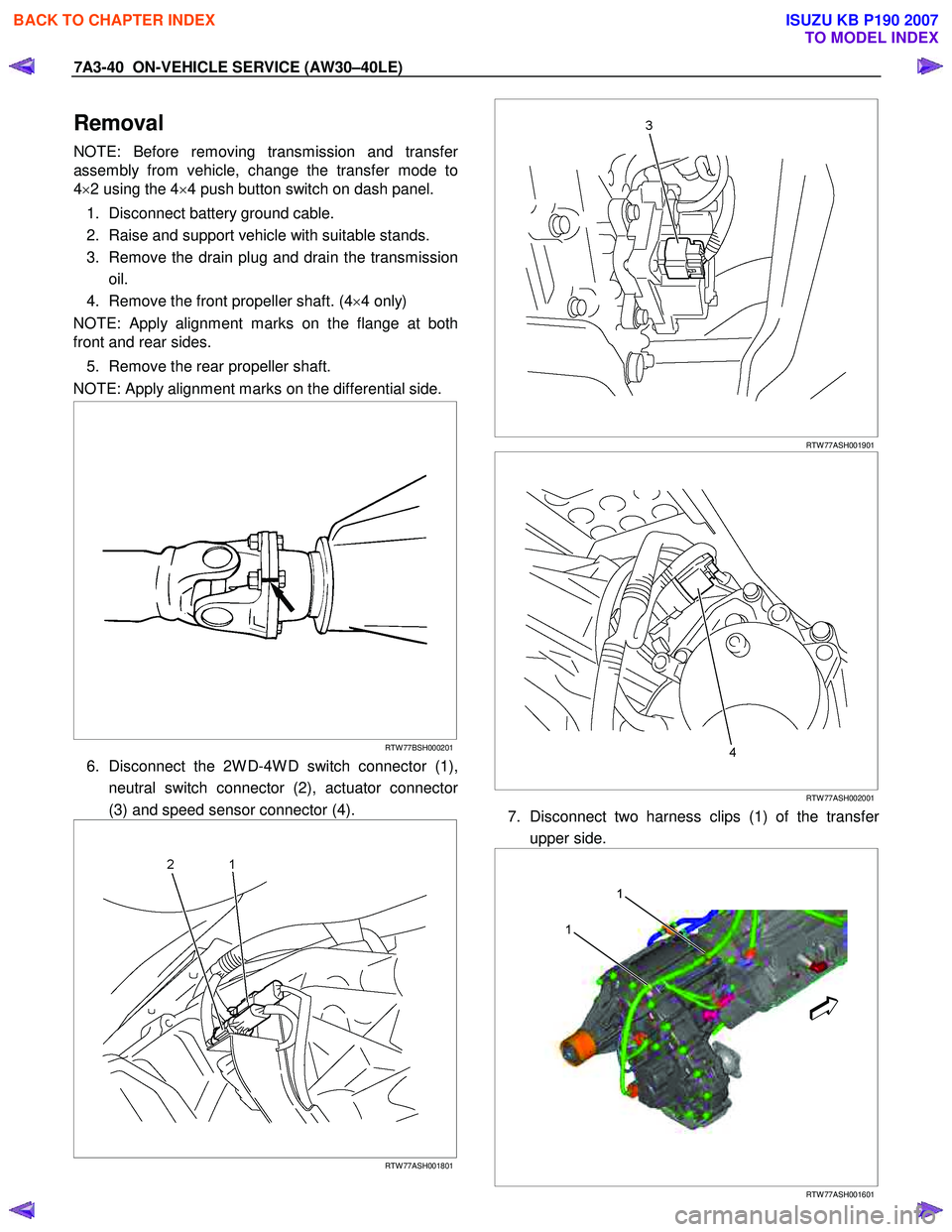
7A3-40 ON-VEHICLE SERVICE (AW30–40LE)
Removal
NOTE: Before removing transmission and transfer
assembly from vehicle, change the transfer mode to
4 ×2 using the 4 ×4 push button switch on dash panel.
1. Disconnect battery ground cable.
2. Raise and support vehicle with suitable stands.
3. Remove the drain plug and drain the transmission oil.
4. Remove the front propeller shaft. (4 ×4 only)
NOTE: Apply alignment marks on the flange at both
front and rear sides.
5. Remove the rear propeller shaft.
NOTE: Apply alignment marks on the differential side.
RTW 77BSH000201
6. Disconnect the 2W D-4W D switch connector (1),
neutral switch connector (2), actuator connecto
r
(3) and speed sensor connector (4).
RTW 77ASH001801
RTW 77ASH001901
RTW 77ASH002001
7. Disconnect two harness clips (1) of the transfer
upper side.
1
1
RTW 77ASH001601
BACK TO CHAPTER INDEX
TO MODEL INDEX
ISUZU KB P190 2007
Page 4615 of 6020

MANUAL TRANSMISSION 7B1-9
6. Remove the gear control lever.
7. Raise and support the vehicle with suitable stands.
8. Remove the rear propeller shaft.
NOTE: Apply alignment marks on the flange at the
differential side.
401RS023
9. Loosen the front exhaust pipe fixing nuts at the engine side but do not remove them. (Diesel engine
only)
RTW 67BSH000101
10. Disconnect the harness connectors and clips on the
transmission.
• Neutral Switch
• Back up Switch
• Car Speed Sensor
11. Remove the fuel pipe bracket with pipes from the transmission.
Diesel engine
220R300012
Legend
(1) Bolt
(2) Nut
(3) Fuel Pipe Assembly
C24SE
Scan-1
BACK TO CHAPTER INDEX
TO MODEL INDEX
ISUZU KB P190 2007
Page 4669 of 6020

MANUAL TRANSMISSION 7B1-63
6. Remove the gear control lever.
7. Raise and support the vehicle with suitable stands.
8. Remove the rear propeller shaft.
NOTE: Apply alignment marks on the flange at the
differential side.
9. Remove the front propeller shaft.
NOTE:
Apply alignment marks on the flange at both
front and rear sides.
401RS023
10. Loosen the front exhaust pipe fixing nuts at the engine side but do not remove them. (Diesel engine
only)
RTW 67BSH000101
11. Disconnect the harness connectors and clips on the
transmission and transfer.
• Neutral Switch: Transmission
• Back up Switch
• Actuator
• 2W D-4W D Switch
• Neutral Switch: Transfer
• Car Speed Sensor
810R300069
Legend
(1) Neutral Switch Connector: Transmission
(2) Back up Switch Connector
(3) Speed Sensor Connector
(4) Actuator Connector
(5) 2W D - 4W D Switch Connector
(6) Neutral Switch Connector: Transfer
BACK TO CHAPTER INDEX
TO MODEL INDEX
ISUZU KB P190 2007
Page 4728 of 6020
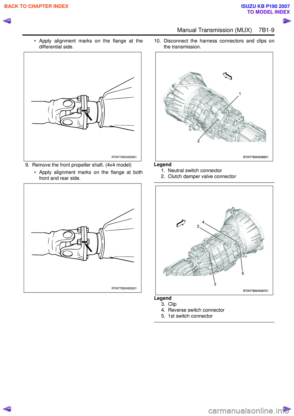
Manual Transmission (MUX) 7B1-9
• Apply alignment marks on the flange at thedifferential side.
9. Remove the front propeller shaft. (4x4 model) • Apply alignment marks on the flange at bothfront and rear side. 10. Disconnect the harness connectors and clips on
the transmission.
Legend 1. Neutral switch connector
2. Clutch damper valve connector
Legend 3. Clip
4. Reverse switch connector
5. 1st switch connector
RTW77BSH000201
RTW77BSH000201
RTW77BSH006601
1
2
RTW77BSH006701
3
3 54
BACK TO CHAPTER INDEX
TO MODEL INDEX
ISUZU KB P190 2007